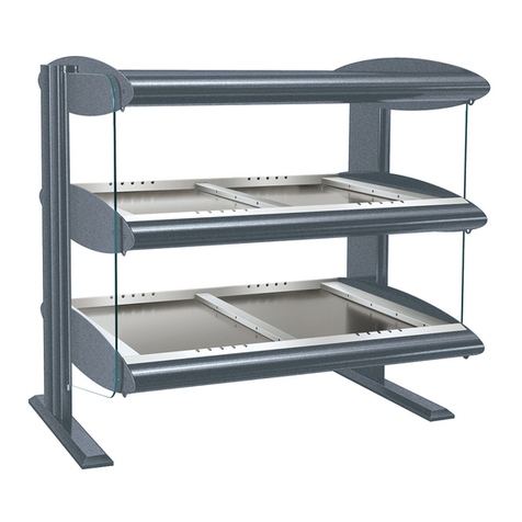
Arneg Aspen 2 TCBM VCA Guide

Aspen 2 TCPW-TCBM
05060055 00 30/08/2007 1
ILLUSTRAZIONI
ILLUSTRATIONS
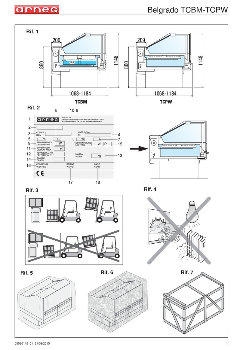
ABBILDUNGEN
ILLUSTRATIONS
ILLUSTRACIONES
ИЛЛЮСТРАЦИИ 1
2
3
150
885
1281
552
1177
300
150
885
1281
552
1177
300
H O
2
H O
HO
2
Aspen 2 TCBM VCA Aspen 2 TCPW VCA
VIA VENEZIA 58 - CAMPO SAN MARTINO - PADOVA - ITALY
S.p.a.
CODICE
ITEM
MATRICOLA
S/N
SBRINAMENTO
DEFROSTING
SUPERF.ESP.
DISPLAY AREA
REFRIGERANTE
REFRIGERANT
CLASSE
CLASS
ILLUMINAZIONE
LIGHTING
MASSA
WEIGHT
COMMESSA
W.SCHED
ORDINE
W.ORD.
ANNO
YEAR
W
m
2
IP
kg
V Hz W
A
1
2
3
5
9
12
14
16
17 18
11
4
7
15
13
10
6 8
W
Max 25mm
Rif. 1
Rif. 2
Rif. 3 Rif. 4

Aspen 2 TCPW-TCBM
205060055 00 30/08/2007
4
5
6
Scarico acqua
Water discharge
Entrata acqua
Water entrance
Livello acqua / Water level
80
H O
2
Hmax 65mm
H O
HO
2
Rif. 6
Rif.10
Rif. 5
Rif. 9
Rif. 8
Rif. 11
Rif. 7

Aspen 2 TCPW-TCBM
05060055 00 30/08/2007 3
7
21
3
PLAFONIERA SUPERIORE
UPPER CANOPY
1
I1 I2
3P+N 400V 50/60HZ
POWER SUPPLY
ALIMENTAZIONE
p.03
p.04
p.02
p.01
UVWN
R1 R2NN
RESISTENZA VASCA 900W
BASIN HEATER 900W
RESISTENZA VASCA 900W
BASIN HEATER 900W
5A
FR2
5A
FR1
p.16
p.15
QS
R2R1
5A
FI1
p.18
5A
FI2
I1 I2
p.19
LEGENDA
SEZIONATORE GENERALE 4P 32A
MAIN BREAKER 4P 32A
QS
CONTATT.RESISTENZE VASCA R1-R2-R3
BASIN HEATER CONTACTOR R1-R2-R3
KA1
A1 TERMOSTATO TEMP.VASCA 0/90°C
BASIN TEMPERAT.THERMOSTAT 0/90°C
GREEN SUPPLY DIAL LAMP
SPIA RETE VERDE
HL1
INTERRUTTORE ILLUMINAZIONE
LIGHT SWITCH
SA1
ST TERMOSTATO SIC.PK1-1CLL 145-131°C
SAFETY THERMOST.PK1-1CLL 145-131°C
R1-2-3 RESISTENZA VASCA 900W
BASIN HEATER 900W
LAMPADA ALOGENA 200W 230V
HALOGEN LAMP 200W 230V
I1-2
ST ST ST 1 2
FUSIBILI 6,3 x 32 GF
FUSES 6,3 x 32 GF
F....
CANOPY CONNECTION WIRE
CAVO DI COLLEGAMENTO ALLA PLAFONIERA
NI
3
SA1
p.21
CONTATT.ILLUMIN.PLAF.I1-I2
CANOPY LIGHTING CONTACTOR I1-I2
KA2
KA1
p.17
5A
FR3
R3 N
ST
RESISTENZA VASCA 900W
BASIN HEATER 900W
R3
0.5A
FS
KA1
A1
p.05
KA2
2N
5A
F2
p.14
SA2
M
VENTILATORI ANTI-CONDENSA
ANTI-MIST FANS
2
INTERRUT.VENTILATORI ANTI-CONDENSA
ANTI-MIST FAN SWITCH
SA2
KA2
p.20
HL2HL1
p.06
SPIA TERMOSTATO ARANCIO
THERMOSTAT DIAL LAMP ORANGE
HL2
0.5A
FA
KA3
5A
F5
p.09
SA3
HL3
p.07
p.10
p.08
p.11
N5
VALVOLA LIQUIDA
SOLENOID VALVE
KA3
11 12
INTERRUTTORE LIVELLO ACQUA
WATER LEVEL SWITCH
RELE' CONTROLLO LIVELLO ACQUA
WATER LEVEL CONTROLL RELAY
KA3
SP
p.12
p.13
3
INTERRUT.CARICO-SCARICO ACQUA
WATER CHARGE-DISCHARGE SWITCH
SA3
HL3 SPIA ALLARME LIVELLO MINIMO ACQUA
WATER MIN.LEVEL ALARM LAMP
Dis.N° D5A14686
Schema elettrico BM L=937 / Electric diagram BM L=937

Aspen 2 TCPW-TCBM
405060055 00 30/08/2007
8
3P+N 400V 50/60HZ
POWER SUPPLY
ALIMENTAZIONE
p.03
p.04
p.02
p.01
UVWN
R1 R2NN
RESISTENZA VASCA 900W
BASIN HEATER 900W
RESISTENZA VASCA 900W
BASIN HEATER 900W
5A
FR2
5A
FR1
p.15
p.14
QS
R2R1
5A
FI1
p.17
5A
FI2
I1 I2
5A
FI3
p.19
I3
3
p.18
LEGENDA
SEZIONATORE GENERALE 4P 32A
MAIN BREAKER 4P 32A
QS
CONTATT.RESISTENZE VASCA R1-R2-R3
BASIN HEATER CONTACTOR R1-R2-R3
KA1
A1
TERMOSTATO TEMP.VASCA 0/90°C
BASIN TEMPERAT.THERMOSTAT 0/90°C
GREEN SUPPLY DIAL LAMP
SPIA RETE VERDE
HL1
INTERRUTTORE ILLUMINAZIONE
LIGHT SWITCH
SA1
ST
TERMOSTATO SIC.PK1-1CLL 145-131°C
SAFETY THERMOST.PK1-1CLL 145-131°C
R1-2-3 RESISTENZA VASCA 900W
BASIN HEATER 900W
LAMPADA ALOGENA 300W 230V
HALOGEN LAMP 300W 230V
I1-2-3
ST ST ST 1 2
FUSIBILI 6,3 x 32 GF
FUSES 6,3 x 32 GF
F....
21
43
PLAFONIERA SUPERIORE
UPPER CANOPY
1
CANOPY CONNECTION WIRE
CAVO DI COLLEGAMENTO ALLA PLAFONIERA
NI
4
SA1
p.21
CONTATT.ILLUMIN.PLAF.I1-I2-I3
CANOPY LIGHTING CONTACTOR I1-I2-I3
KA2
KA1
p.16
5A
FR3
R3 N
ST
RESISTENZA VASCA 900W
BASIN HEATER 900W
R3
0.5A
FS
KA1
A1
p.05
KA2
2N
5A
F2
p.13
SA2
M
VENTILATORI ANTI-CONDENSA
ANTI-MIST FANS
2
INTERRUT.VENTILATORI ANTI-CONDENSA
ANTI-MIST FAN SWITCH
SA2
KA2
I1 I2 I3
p.20
HL2HL1
SPIA TERMOSTATO ARANCIO
THERMOSTAT DIAL LAMP ORANGE
HL2
0.5A
FA
KA3
5A
F5
p.08
SA3
HL3
p.06
p.09
p.07
p.10
N5
VALVOLA LIQUIDA
SOLENOID VALVE
KA3
11 12
INTERRUTTORE LIVELLO ACQUA
WATER LEVEL SWITCH
RELE' CONTROLLO LIVELLO ACQUA
WATER LEVEL CONTROLL RELAY
KA3
SP
p.11
p.12
3
INTERRUT.CARICO-SCARICO ACQUA
WATER CHARGE-DISCHARGE SWITCH
SA3
HL3 SPIA ALLARME LIVELLO MINIMO ACQUA
WATER MIN.LEVEL ALARM LAMP
Dis.N° D5A14620
Schema elettrico BM L=1250 / Electric diagram BM L=1250

Aspen 2 TCPW-TCBM
05060055 00 30/08/2007 5
9
3P+N 400V 50/60HZ
POWER SUPPLY
ALIMENTAZIONE
p.03
p.04
p.02
p.01
UVWN
R1 R2NN
RESISTENZA VASCA 900W
BASIN HEATER 900W
RESISTENZA VASCA 900W
BASIN HEATER 900W
5A
FR2
5A
FR1
p.09
p.08
QS
R2R1
5A
FI1
p.11
5A
FI2
I1 I2
p.12
LEGENDA
SEZIONATORE GENERALE 4P 32A
MAIN BREAKER 4P 32A
QS
CONTATT.RESISTENZE VASCA R1-R2-R3
BASIN HEATER CONTACTOR R1-R2-R3
KA1
A1 TERMOSTATO TEMP.VASCA 0/90°C
BASIN TEMPERAT.THERMOSTAT 0/90°C
GREEN SUPPLY DIAL LAMP
SPIA RETE VERDE
HL1
INTERRUTTORE ILLUMINAZIONE
LIGHT SWITCH
SA1
ST TERMOSTATO SIC.PK1-1CLL 145-131°C
SAFETY THERMOST.PK1-1CLL 145-131°C
R1-2-3 RESISTENZA VASCA 900W
BASIN HEATER 900W
LAMPADA ALOGENA 200W 230V
HALOGEN LAMP 200W 230V
I1-2
ST ST ST
1 2
FUSIBILI 6,3 x 32 GF
FUSES 6,3 x 32 GF
F....
21
3
PLAFONIERA SUPERIORE
UPPER CANOPY
1
CANOPY CONNECTION WIRE
CAVO DI COLLEGAMENTO ALLA PLAFONIERA
NI
3
SA1
p.14
CONTATT.ILLUMIN.PLAF.I1-I2-I3
CANOPY LIGHTING CONTACTOR I1-I2-I3
KA2
KA1
p.10
5A
FR3
R3 N
ST
RESISTENZA VASCA 900W
BASIN HEATER 900W
R3
0.5A
FS
KA1
A1
p.05
p.06
KA2
2N
5A
F2
p.07
SA2
M
VENTILATORI ANTI-CONDENSA
ANTI-MIST FANS
2
INTERRUT.VENTILATORI ANTI-CONDENSA
ANTI-MIST FAN SWITCH
SA2
KA2
I1 I2
p.13
HL2HL1
SPIA TERMOSTATO ARANCIO
THERMOSTAT DIAL LAMP ORANGE
HL2
Dis.N° D5A14674
Schema elettrico PW L=937 / Electric diagram PW L=937

Aspen 2 TCPW-TCBM
605060055 00 30/08/2007
10
3P+N 400V 50/60HZ
POWER SUPPLY
ALIMENTAZIONE
p.03
p.04
p.02
p.01
UVWN
R1 R2NN
RESISTENZA VASCA 900W
BASIN HEATER 900W
RESISTENZA VASCA 900W
BASIN HEATER 900W
5A
FR2
5A
FR1
p.09
p.08
QS
R2R1
5A
FI1
p.11
5A
FI2
I1 I2
5A
FI3
p.13
I3
3
p.12
ST ST ST
1 2
21
43
PLAFONIERA SUPERIORE
UPPER CANOPY
1
CANOPY CONNECTION WIRE
CAVO DI COLLEGAMENTO ALLA PLAFONIERA
NI
4
SA1
p.15
KA1
p.10
5A
FR3
R3 N
ST
RESISTENZA VASCA 900W
BASIN HEATER 900W
R3
0.5A
FS
KA1
A1
p.05
p.06
KA2
2N
5A
F2
p.07
SA2
M
VENTILATORI ANTI-CONDENSA
ANTI-MIST FANS
2
KA2
I1 I2 I3
p.14
HL2HL1
LEGENDA
SEZIONATORE GENERALE 4P 32A
MAIN BREAKER 4P 32A
QS
CONTATT.RESISTENZE VASCA R1-R2-R3
BASIN HEATER CONTACTOR R1-R2-R3
KA1
A1
TERMOSTATO TEMP.VASCA 0/90°C
BASIN TEMPERAT.THERMOSTAT 0/90°C
GREEN SUPPLY DIAL LAMP
SPIA RETE VERDE
HL1
INTERRUTTORE ILLUMINAZIONE
LIGHT SWITCH
SA1
ST
TERMOSTATO SIC.PK1-1CLL 145-131°C
SAFETY THERMOST.PK1-1CLL 145-131°C
R1-2 RESISTENZA VASCA 900W
BASIN HEATER 900W
LAMPADA ALOGENA 300W 230V
HALOGEN LAMP 300W 230V
I1-2-3
FUSIBILI 6,3 x 32 GF
FUSES 6,3 x 32 GF
F....
CONTATT.ILLUMIN.PLAF.I1-I2-I3
CANOPY LIGHTING CONTACTOR I1-I2-I3
KA2
INTERRUT.VENTILATORI ANTI-CONDENSA
ANTI-MIST FAN SWITCH
SA2
SPIA TERMOSTATO ARANCIO
THERMOSTAT DIAL LAMP ORANGE
HL2
Dis.N° D5A14619
Schema elettrico PW L=1250 / Electric diagram PW L=1250

Aspen 2 TCPW-TCBM
05060055 00 30/08/2007 7
Manuale di Installazione e Uso
INDICE
ILLUSTRAZIONI ................................................................................................... 1
Introduzione - Scopo del manuale/Campo di applicazione ................................... 8
Presentazione - Uso previsto (Fig. 1).................................................................... 8
Dati Tecnici ........................................................................................................... 8
Identificazione - Dati di targa (Fig. 2) .................................................................... 9
Il Trasporto (Fig. 3)................................................................................................ 9
Ricezione e prima pulizia ...................................................................................... 9
Installazione e condizioni ambientali (Fig. 3) ........................................................ 9
Collegamento elettrico (Fig. 7 - Fig. 10)................................................................ 10
Lampade riscaldanti (Fig. 3).................................................................................. 10
Accensione............................................................................................................ 10
Carico/scarico dell’acqua (versione bagnomaria) (Fig. 4)..................................... 11
Sistema di disappannamento (Fig. 5 Rif. 8) .......................................................... 11
Impostazione e controllo della temperatura (Fig. 6).............................................. 11
Il caricamento del mobile ...................................................................................... 11
Manutenzione e pulizia ......................................................................................... 12
Smantellamento del mobile................................................................................... 13
Consigli utili ........................................................................................................... 13
Dichiarazione di Conformità .................................................................................. 51

Aspen 2 TCPW-TCBM
805060055 00 30/08/2007
1. Introduzione - Scopo del manuale/Campo di applicazione
Questo manuale d’istruzioni riguarda la linea di mobili tavola calda modello Aspen 2 TCBM-TCPW.
Le informazioni che seguono hanno lo scopo di fornire indicazioni relative a:
- Uso del mobile;
- Caratteristiche tecniche;
- Installazione e montaggio;
- Informazioni per il personale addetto all’uso;
- Interventi di manutenzione.
Il manuale è da considerarsi parte del mobile e deve essere conservato per tutta la durata dello
stesso.
Il costruttore si ritiene sollevato da eventuali responsabilità nei seguenti casi:
- Uso improprio del mobile;
- Installazione non corretta, non eseguita secondo le norme indicate;
- Difetti di alimentazione elettrica;
- Gravi mancanze nella manutenzione prevista;
- Modifiche ed interventi non autorizzati;
- Utilizzo di ricambi non originali;
- Inosservanza parziale o totale delle istruzioni;
N.B.Gli apparecchi elettrici possono essere pericolosi per la salute.
Le normative e le leggi vigenti devono essere rispettate durante l’installazione e l’impiego.
Qualsiasi persona usi questo mobile dovrà leggere questo manuale.
2. Presentazione - Uso previsto (Fig. 1)
Aspen 2 TCBM-TCPW (Fig. 1), è un espositore adatto alla presentazione e alla vendita di cibi cotti
pronti da consumare.
E’ disponibile in 2 versioni:
- Tavola Calda Bagnomaria BM: con sistema di riscaldamento dell’acqua esterno alla vasca;
- Tavola calda secca PW: con sistema di riscaldamento per mezzo di resistenze poste sotto il piano
vasca.
3. Dati Tecnici
4. Norme e certificazioni
Le norme di riferimento secondo cui il mobile è stato collaudato ed omologato sono:
EN 60335-2-49; EN 60335-2-50; EN 61000-3-2; EN 61000-3-3; EN 55014.
CLASSI CLIMATICHE AMBIENTALI
Questi mobili sono stati verificati nel rispetto della classe climatica 3 (25°C; U.R.60%):
Descrizione
U.M.
Aspen90 TCBM VCA Aspen90 TCPW VCA
Carenato 06211500 06211502 06211200 06211202
Zamponi 06217900 06217902 06211300 06211302
Lunghezza interna mm 937 1250 937 1250
Illuminazione (lampade riscaldanti) n° x W 2x300 3x300 2x300 3x300
Resistenza vasca 3x900
Ventilatore anticondensa 1x6,5 1x6,5 1x6,5 1x6,5
Termostato T&G 711.11228.00A 0-90°C
Termometro Arthermo R088 FBNN 0/120°C
Termostato di sicurezza Texas Instruments PK1-1CLL T=145°C Diff=14°
Alimentazione 400 V 3P+N 50/60Hz
I DATI TECNICI E LE CARATTERISTICHE POSSONO ESSERE SOGGETTI A CAMBIAMENTI OPPURE A MODIFICHE MIGLIORATIVE SENZA ALCUN OBBLIGO DI PREAVVISO
Classe climatica Temp.bulbo secco Umidità relativa Punto di rugiada
1 16°C 80% 12°C
2 22°C 65% 15°C
325°C 60% 17°C
4 30°C 55% 20°C
5 40°C 40% 24°C
6 27°C 70% 21°C

Aspen 2 TCPW-TCBM
05060055 00 30/08/2007 9
I mobili rispondono ai requisiti essenziali richiesti dalle seguenti direttive:
- Direttiva Macchine 98/37 CEE;
- Direttiva Compatibilità elettromagnetica 89/336 CEE e successive modifiche 92/31 CEE,
93/68 CEE;
- Direttiva Bassa Tensione 2006/95/CE e successiva modifica 93/68 CEE.
5. Identificazione - Dati di targa (Fig. 2)
Sul retro del mobile è presente la targa matricolare con tutti i dati caratteristici:
1 Nome ed indirizzo del costruttore
2 Nome e lunghezza del mobile
3 Codice del mobile
4 Numero di matricola del mobile
5 Tensione di alimentazione
6 Frequenza di alimentazione
7 Corrente a regime assorbita
8 Potenza elettrica assorbita
9 Potenza elettrica a regime assorbita nella fase di sbrinamento (Cavi caldi+ventilatore
evaporatore)
10 Potenza di illuminazione (ove prevista)
11 Superficie di esposizione utile
12 Tipo di fluido frigorigeno con cui funziona l’impianto
13 Massa di gas frigorigeno con cui è caricato ogni singolo impianto
14 Classe climatica ambientale e temperatura di riferimento
15 Classe di protezione contro l’umidità
16 Numero della commessa con cui è stato prodotto il mobile
17 Numero d’ordine con cui è stato messo in produzione il mobile
18 Anno di produzione del mobile
Per l’identificazione del mobile, in caso di richiesta di assistenza tecnica, è sufficiente comunicare:
- il nome del prodotto(Fig. 2 - 2);
- il numero di matricola(Fig. 2 - 4);
- il numero di commessa(Fig. 2 - 18).
6. Il Trasporto (Fig. 3)
Il mobile è provvisto di un supporto in legno fissato alla base per la movimentazione con carrelli a
forca.
Utilizzare un carrello elevatore a mano o elettrico idoneo al sollevamento del mobile in questione.
7. Ricezione e prima pulizia
Al ricevimento del mobile:
- Assicurarsi che l’imballo sia integro e non presenti danni evidenti;
- Curare l’operazione di disimballo in modo da non arrecare danno al mobile;
- Controllare il mobile in ogni sua parte verificando l’integrità dei suoi componenti;
- In caso si riscontrino dei danneggiamenti chiamare immediatamente la società di fornitura;
- Procedere ad una prima pulizia utilizzando prodotti neutri, asciugare con un panno morbido, non
usare sostanze abrasive o spugne metalliche.
Per un corretto smaltimento dell’imballo tenere presente che è composto da:
- Legno - Polistirolo - Politene - PVC - Cartone.
Ai sensi della direttiva CEE 94/62 si dichiara l’idoneità dei materiali sopra citati.
8. Installazione e condizioni ambientali (Fig. 3)
Per l’installazione attenersi a quanto segue:
- Non posizionare il mobile:
in ambienti con presenza di sostanze gassose esplosive;
all’aria aperta e quindi agli agenti atmosferici.
- Togliere i supporti in legno alla base (utilizzati per il trasporto) e montare i piedini regolabili (Rif. 2)
posizionandoli in modo tale da portare il mobile in orizzontale aiutandosi con una livella (Rif. 1) per
controllarne l’assetto.
Aspen 2 TCPW-TCBM
10 05060055 00 30/08/2007
- Se il mobile viene spostato ripetere il controllo del livellamento.
- Prima di collegare il mobile alla linea elettrica accertarsi che i dati di targa corrispondano alle
caratteristiche dell’impianto elettrico a cui deve essere allacciato.
N.B.Tutte queste operazioni devono essere eseguite da personale tecnico specializzato.
9. Collegamento elettrico (Fig. 7 - Fig. 10)
- Istruire l’operatore sulla posizione dell’interruttore in modo tale che possa essere raggiunto
tempestivamente in caso di EMERGENZA.
- L’impianto elettrico deve essere provvisto di messa a terra.
- Controllare prima di tutto che la tensione di alimentazione sia quella indicata sui dati di targa (Fig. 2).
- Per garantire un funzionamento regolare, è necessario che la variazione massima di tensione sia
compresa tra +/- 6% del valore nominale.
- Verificare che la linea di alimentazione abbia i cavi di sezione adeguata, sia protetta contro le
sovracorrenti e le dispersioni verso massa in conformità alle norme vigenti.
- Per linee di alimentazione di lunghezza superiore a 4-5 m, aumentare in modo adeguato la sezione
dei cavi.
- Nel caso di interruzione dell’alimentazione elettrica, verificare che tutte le apparecchiature elettriche
del negozio siano in grado di riavviarsi senza provocare l’intervento delle protezioni di sovraccarico,
in caso contrario modificare l’impianto in modo da differenziare l’avviamento dei vari dispositivi.
- L’installatore deve fornire i dispositivi di ancoraggio per tutti i cavi in entrata e uscita del mobile.
L’interruttore automatico magnetotermico deve essere tale da non aprire il circuito sul neutro
senza contemporaneamente aprirlo sulle fasi ed in ogni caso la distanza di apertura dei
contatti deve essere di almeno 3 mm.
N.B.Tutte queste operazioni devono essere eseguite da personale tecnico specializzato.
10.Lampade riscaldanti (Fig. 3)
Per garantire il mantenimento della temperatura dei prodotti esposti il mobile è fornito di lampade
riscaldanti (Rif. 3).
L’interruttore delle lampade riscaldanti si trova sul pannello di controllo, par. 11 n° 5.
11. Accensione
- Ruotare l'interruttore generale nella posizione ON, in questo modo si avrà la possibilità di verificare
se il pannello di controllo ed i relativi componenti sono utilizzabili.
- Tutti i comandi sono dotati di spia luminosa che evidenzia il funzionamento del componente.
- L'unico interruttore non luminoso è quello d'attivazione della plafoniera riscaldante superiore.
Il pannello di controllo si trova sulla parte inferiore del mobile nella zona operatore ed è costituito da:
- 1 - Interruttore generale;
- 2 - Linea;
- 3 - Termostato vasca;
- 4 - Spia riscaldamento;
- 5 - Riscaldamento plafoniera;
- 6 - Ventilazione anticondensa.
- 7 - Interruttore Carico/Scarico (versione bagnomaria)
12 34567

Aspen 2 TCPW-TCBM
05060055 00 30/08/2007 11
12.Carico/scarico dell’acqua (versione bagnomaria) (Fig. 4)
- Ad interruttore generale in posizione ON è possibile effettuare il carico dell'acqua nella vasca del
mobile.
- Assicurarsi che la saracinesca meccanica (Rif. 6) sia chiusa. Selezionare l'interruttore carico/
scarico acqua in posizione 1, in questo modo si avvia il carico automatico dell'acqua, l'operazione
terminerà in modo automatico quando il livello dell'acqua avrà raggiunto il sensore di livello (Rif. 5).
- Con l'interruttore carico/scarico acqua in posizione 1 si avrà il ripristino automatico del livello della
stessa.
- Per garantire una pulizia completa del mobile, talvolta si deve svuotare l'acqua dalla vasca di
contenimento.
- Tale operazione si effettua spostando l'interruttore carico/scarico acqua in posizione 2, in maniera di
disinserire il carico automatico dell'acqua, ed aprendo la saracinesca meccanica (Rif. 6) in modo di
svuotare completamente la vasca di contenimento.
- Riportare la leva della saracinesca nella posizione di carico acqua, a svuotamento avvenuto.
13.Sistema di disappannamento (Fig. 5 Rif. 8)
- Il mobile è dotato di ventilatori, posti sotto il vetro anteriore, che permettono di evitare fastidiosi
fenomeni di condensa sulle superfici vetrate.
- E' consigliabile utilizzare ed attivare questo sistema solo quando necessita, a condizioni normali
d'utilizzo il sistema di disappannamento non deve essere in funzione.
14.Impostazione e controllo della temperatura (Fig. 6)
Ruotare il pomello del termostato vasca (par. 11 n. 3) selezionando la temperatura desiderata.
Di solito si consiglia di impostarlo a 90°C.
Il controllo della temperatura si esegue attraverso il termometro meccanico (Rif. 10) posto sulla parte
posteriore del mobile vicino al pannello di controllo e attraverso il termometro posto sul telaio inox
(Rif. 11).
15.Il caricamento del mobile
Per il rifornimento del mobile è necessario osservare alcune regole importanti:
- Far riscaldare il mobile per almeno 2 ore in modo di raggiungere una temperatura interna
accettabile.
- Gli alimenti caldi vanno caricati nel mobile immediatamente dopo la cottura ed in ogni caso ad una
temperatura non inferiore a 65°.
- Le tavole calde non sono progettate per riscaldare e tantomeno cuocere i cibi ma sono adatte alla
conservazione del prodotto esposto.
- Controllare più volte il giorno che la temperatura interna corrisponda alla giusta condizione di
mantenimento. La temperatura di conservazione, per la maggior parte dei prodotti, è di 65°C.
- Questa temperatura tende a far continuare la cottura d'alcuni cibi; pertanto si consiglia di tenere
nella tavola calda piccole quantità di prodotto nei periodi di scarsa vendita.
- Disporre i prodotti su un solo strato in modo tale che siano a contatto diretto con la superficie
riscaldante.
- Prodotti liquidi quali sughi e salse si possono mantenere fino a temperatura di 82°C.
- Su richiesta è possibile avere dei contenitori Gastro Norm che rispondono alla normativa EN
631disponibili in diversi modelli nelle profondità 20, 40, 65, 150 e 200 mm (Fig. 5 Rif. 9).
ATTENZIONE! Nella versione TCPW è possibile impiegare i contenitori Gastro Norm con
profondità massima di 65mm.
- Controllare con l’ausilio di un termometro la temperatura interna dei prodotti esposti.

Aspen 2 TCPW-TCBM
12 05060055 00 30/08/2007
16.Manutenzione e pulizia
ATTENZIONE! PRIMA DI QUALSIASI OPERAZIONE DI MANUTENZIONE E PULIZIA TOGLIERE
TENSIONE AL BANCO TRAMITE L’INTERRUTTORE GENERALE E ATTENDERE CHE
LE PARTI RISCALDATE SI SIANO RAFFREDDATE.
I prodotti alimentari possono deteriorarsi a causa di microbi e batteri.
Il rispetto delle norme igieniche è indispensabile per garantire la tutela della salute del consumatore.
Per garantire una pulizia completa del mobile versione BM (bagnomaria), talvolta si deve svuotare
l'acqua dalla vasca di contenimento (vedi istruzioni par. 12).
La pulizia dei mobili viene distinta come segue:
La pulizia delle parti esterne (Giornaliera / Settimanale)
- Pulire con cadenza settimanale tutte le parti esterne del mobile utilizzando detergenti neutri per uso
domestico o acqua e sapone.
- Risciacquare con acqua pulita e asciugare con uno straccio morbido.
- NON usare prodotti abrasivi e solventi che possono in qualche modo alterare le superfici dei mobili.
- NON spruzzare acqua oppure detergente sulle parti elettriche del mobile.
La pulizia delle parti interne (Mensile)
- Aprire i vetri scorrevoli posteriori in modo da accelerare il raffreddamento delle parti riscaldanti del
mobile. Prima di accedere alle parti interne del mobile attendere che la temperatura del
mobile si equilibri con la temperatura ambiente.
- Per la pulizia delle superfici in acciaio od in vetro usare i normali detergenti neutri disponibili in
commercio; risciacquare ed asciugare accuratamente con un panno morbido.
- Eventuali versamenti di alimenti, durante il normale uso del mobile, devono essere puliti
immediatamente con un panno umido.
- Prima di procedere alla pulizia interna di un mobile o di una parte di esso, è necessario:
- Togliere la tensione al mobile tramite l’interruttore generale.
- Svuotarlo completamente dalla merce che contiene.
ATTENZIONE! Nella versione bagnomaria NON urtare il sensore di livello della vasca con qualsiasi
tipo di utensile. Accertarsi che lo scarico dell’acqua non sia ostruito da corpi
estranei.
Si procede poi alla rimozione delle parti amovibili (contenitori Gastro Norm, piatti di esposizione etc.)
che debbono essere lavate con acqua tiepida e detergente contenente un disinfettante, ed infine
asciugare accuratamente.
N.B.Pulire accuratamente i contenitori Gastro Norm (Fig. 5 Rif. 9) ad ogni rinnovo della merce
esposta.
Per proteggere le mani durante tali operazioni è consigliabile l’impiego di guanti da lavoro.
Terminate le operazioni di pulizia rimontare gli elementi amovibili (naturalmente asciutti) e ripristinare
l’alimentazione elettrica.
N.B.Rimontare la protezione dello scarico della vasca di riscaldamento (Fig. 4 Rif. 7 ) ogni volta
che si procede alla pulizia interna.
Evitare che, plafoniere, cavi elettrici e tutte le apparecchiature elettriche in genere vengano bagnate
durante le operazioni di pulizia.

Aspen 2 TCPW-TCBM
05060055 00 30/08/2007 13
17.Smantellamento del mobile
In conformità alle norme per lo smantellamento dei rifiuti nei singoli paesi e per il rispetto
dell’ambiente in cui viviamo, vi invitiamo a dividere le parti del mobile in modo da poterle smaltire
separatamente o a recuperarle.
Tutte le parti che compongono il banco non possono essere smaltite assieme ai rifiuti solidi urbani a
parte i componenti metallici che comunque non figurano tra i rifiuti speciali per la maggior parte dei
paesi europei.
Materiali impiegati nella costruzione del mobile:
- Acciaio inox 18/10 (AISI 304): struttura base del mobile, finiture varie
- Tubo in ferro: telaio inferiore
- Lamiera zincata: lamiere interne, pannelli inferiori, pannelli verniciati
- Vetro temprato: vetrate perimetrali
- Lana di roccia cartone refrattario: isolamento termico
- PVC: profili paracolpi, profilo chiusura zoccolo
18.Consigli utili
Si consiglia un’attenta lettura del Manuale di Installazione ed uso affinché, l’operatore, in caso di
guasto sarà in grado di fornire telefonicamente informazioni più precise all’ Assistenza tecnica.
Prima di effettuare una qualsiasi operazione di manutenzione, assicurarsi che l’alimentazione
elettrica sia staccata.
Nel caso in cui il cliente dovesse notare una qualsiasi anomalia nel funzionamento del mobile,
prima di allarmarsi e contattare il Servizio Assistenza, è fondamentale che siano verificati i
seguenti punti:
- Per evitare dispersioni di calore e danni alla piastra è utile usare recipienti con fondo piano e di
diametro non inferiore a quello della piastra;
- Eliminare immediatamente ogni minimo inconveniente rilevato (viti allentate, lampade fulminate,
etc.);
- Effettuare con assoluta regolarità tutte le operazioni di manutenzione preventiva;
- Evitare di toccare la piastra di cottura con parti del corpo umido;
- Evitare di toccare le lampade riscaldanti, pericolo di ustione;
- NON eseguire operazioni improprie e pericolose;
- Evitare che il cavo di eventuali strumenti (ad esempio bilance) finisca sulle parti calde del mobile;
- NON usare di liquidi infiammabili nei pressi delle parti calde;
- Evitare l’impiego di pentole instabili o deformate;
- Evitare di lasciare accese le piastre senza pentole;
- IN CASO DI FUGA DI GAS O DI INCENDIO: Non sostare con la testa nel vano dove è posizionato
il mobile se questo non è opportunatamente arieggiato.Scollegare il mobile agendo sull’interruttore
generale a monte dell’apparecchiatura.NON USARE ACQUA PER SPEGNERE LE FIAMME MA
SOLO ESTINTORI A SECCO.
OGNI ALTRO USO NON ESPLICITAMENTE INDICATO IN QUESTO MANUALE È DA
CONSIDERARSI PERICOLOSO ED IL COSTRUTTORE NON PUÒ ESSERE RITENUTO
RESPONSABILE PER EVENTUALI DANNI DERIVANTI DA USO IMPROPRIO, ERRONEO E
IRRAGIONEVOLE.
NUMERI UTILI:CENTRALINO +39 0499699333 - FAX +39 9699444 - CALL CENTER 848 800225

Aspen 2 TCPW-TCBM
14 05060055 00 30/08/2007
Installation and Use Manual
CONTENTS
ILLUSTRATIONS .................................................................................................. 1
Introduction - Purpose of the manual/Field of application ..................................... 15
Presentation - Intended use (Fig. 1)...................................................................... 15
Technical details ................................................................................................... 15
Identification - Nameplate (Fig. 2) ......................................................................... 16
Transportation (Fig. 3)........................................................................................... 16
Delivery and first cleaning ..................................................................................... 16
Installation and environmental conditions (Fig. 3)................................................. 16
Electric connections (Fig. 7 - Fig. 10).................................................................... 17
Heating lamps (Fig. 3)........................................................................................... 17
Turning on the counter .......................................................................................... 17
Filling and emptying the water tank (bain-marie version) (Fig. 4) ......................... 18
Demisting system (Fig. 5 Rif. 8) ............................................................................ 18
Setting and controlling the temperature (Fig. 6).................................................... 18
Loading the counter .............................................................................................. 18
Maintenance and cleaning .................................................................................... 19
Dismantling the counter ........................................................................................ 20
Suggestions .......................................................................................................... 20
Conformity Declaration.......................................................................................... 51

Aspen 2 TCPW-TCBM
05060055 00 30/08/2007 15
1. Introduction - Purpose of the manual/Field of application
This manual refers to the Aspen 2 TCBM-TCPW hot-dish counter.
The manual provides information on:
- Using the counter;
- Technical features;
- Installation and assembly;
- Instructions for users;
- Maintenance operations.
This manual should be considered part of the counter and must be preserved for its entire life.
The manufacturer holds itself exempt from any responsibilities arising under the following
circumstances:
- Improper use of the counter;
- Incorrect installation, carried out without following the instructions;
- Faults in the power supply;
- Failure to carry out scheduled maintenance;
- Unauthorized changes and operations;
- Use of non-original spare parts;
- Failure to comply with the instructions, in whole or in part;
NOTE Electrical appliances can be dangerous for your health.
Respect the regulations and laws in force during installation and use.
All persons involved in using the counter are required to read this manual.
2. Presentation - Intended use (Fig. 1)
Aspen 2 TCBM-TCPW (Fig. 1), is a counter for displaying and selling cooked foods for immediate
consumption.
The counter is available in 2 versions:
- Bain-Marie hot-dish counter BM: with an external water-heating system;
- Dry hot-dish counter PW: with heating provided by resistors located beneath the tank level.
3. Technical details
4. Standards and certifications
The counter has been tested and approved under the following standards of reference:
EN 60335-2-49; EN 60335-2-50; EN 61000-3-2; EN 61000-3-3; EN 55014.
CLIMATE CLASS
The counters have been tested for operating under climate class 3 (25°C; 60% R.H.):
The counters comply with the basic requirements of the following directives:
Description
U.M.
Aspen90 TCBM VCA Aspen90 TCPW VCA
Faired 06211500 06211502 06211200 06211202
Trotters 06217900 06217902 06211300 06211302
Inside length mm 937 1250 937 1250
Lighting (heating lamps) n° x W 2x300 3x300 2x300 3x300
Tank resistor 3x900
Anti-condensation fan 1x6,5 1x6,5 1x6,5 1x6,5
Thermostat T&G 711.11228.00A 0-90°C
Thermometer Arthermo R088 FBNN 0/120°C
Safety thermostat Texas Instruments PK1-1CLL T=145°C Diff=14°
Power supply 400 V 3P+N 50/60Hz
TECHNICAL DETAILS AND FEATURES MAY BE SUBJECT TO CHANGE WITH NO FURTHER NOTICE
Climate class Dry bulb temp. Relative humidity Dew point
1 16°C 80% 12°C
2 22°C 65% 15°C
325°C 60% 17°C
4 30°C 55% 20°C
5 40°C 40% 24°C
6 27°C 70% 21°C

Aspen 2 TCPW-TCBM
16 05060055 00 30/08/2007
- Machinery Directive 98/37 CEE;
- Electromagnetic Compatibility Directive 89/336 CEE and subsequent amendments 92/31 CEE,
93/68 CEE;
- Low Voltage Directive 2006/95/CE and subsequent amendment 93/68 CEE.
5. Identification - Nameplate (Fig. 2)
The nameplate is located at the back of the counter and shows the following information:
1 Manufacturer's name and address
2 Name and length of the counter
3 Counter code number
4 Counter serial number
5 Power supply voltage
6 Power supply frequency
7 Operating current
8 Power absorbed
9 Power absorbed during defrosting (hot wires + evaporator fan)
10 Lighting power (where applicable)
11 Usable display surface
12 Type of refrigerant used
13 Amount of refrigerant loaded into each counter
14 Climate class and reference temperature
15 Class of protection against humidity
16 Production job number
17 Counter production number
18 Year of construction
When contacting our Customer Service, please be ready to provide the following information:
- the product's name (Fig. 2 - 2);
- the serial number (Fig. 2 - 4);
- the job number (Fig. 2 - 18).
6. Transportation (Fig. 3)
The counter is provided with a wooden support at the base to facilitate using a forklift.
Use a hand-operated or electric forklift suitable for the counter's dimensions.
7. Delivery and first cleaning
When taking delivery of the counter:
- Make sure the packing is intact and shows no signs of damage;
- Unpack the counter without damaging it;
- Check all counter parts and make sure they are intact;
- If any damage is found inform your supplier immediately;
- Clean the counter using a neutral detergent and dry with a soft cloth - do not use abrasive materials
or metal sponges.
The following packing materials have been used:
- Wood - Polystyrene - Polythene - PVC - Cardboard.
We certify that the above materials comply with Directive CEE 94/62.
8. Installation and environmental conditions (Fig. 3)
To install the counter follow the instructions below:
- Do not place the counter:
in places containing explosive gases;
outdoors, or directly exposed to the weather.
- Remove the wooden supports at the base (used for transportation), mount the adjustable feet (Rif.
2) and, using a level to check, adjust the feet so that the counter is perfectly horizontal (Rif. 1).
- Every time you move the counter make sure that it is level.
- Before connecting the counter to the power supply, make sure the voltage and frequency
correspond to the requirements printed on the nameplate.

Aspen 2 TCPW-TCBM
05060055 00 30/08/2007 17
NOTE The above operations must be carried out by qualified personnel.
9. Electric connections (Fig. 7 - Fig. 10)
- Inform the operator of the location of the switch so that it can be quickly used in case of
EMERGENCY.
- The electrical system must be adequately grounded.
- First of all make sure that the supply voltage is the same as required on the nameplate (Fig. 2).
- To ensure regular operations, the any voltage variations should fall within +/-6% of the rated voltage.
- Make sure the supply line is provided with wires having an adequate cross-section and is protected
against overcurrents and ground leakage currents as required by law.
- If the supply line is longer than 4-5 metres, use accordingly larger wires.
- In case of power failures, make sure all the electric appliances in the shop can restart without
triggering overcurrent protection; if not, modify the system so that the appliances restart at
staggered times.
- The anchoring for all the wires to and from the counter must be supplied by the installer.
The automatic thermomagnetic switch must not open the circuit on the neutral pole without
opening it on the phases at the same time, and the distance between the contacts should be at
least 3 mm.
NOTE The above operations must be carried out by qualified personnel.
10.Heating lamps (Fig. 3)
The counter is equipped with heating lamps to keep the food on display at the right temperature (Rif. 3).
The lamp switch is located on the control panel, par. 11, no. 5.
11. Turning on the counter
- Turn the main switch to ON; the control panel and all counter parts should turn on immediately.
- The controls are all provided with a light to show their state of activity.
- The only switch without a light controls the ceiling heating lamp.
The control panel is on the lower part of the counter, in the operator's area. The panel contains the
following controls:
- 1 - Main switch;
- 2 - Line;
- 3 - Tank thermostat;
- 4 - Heating light;
- 5 - Ceiling heating;
- 6 - Anti-condensation fan.
- 7 - Fill/Empty switch (bain-marie version)
12 34567

Aspen 2 TCPW-TCBM
18 05060055 00 30/08/2007
12.Filling and emptying the water tank (bain-marie version) (Fig. 4)
- The main switch should be ON to fill the water tank.
- Make sure the mechanical shutter is closed (Rif. 6) Turn the fill/empty switch to 1. The tank will
automatically start to fill with water and stop automatically when the water reaches the level sensor
(Rif. 5).
- When the fill/empty switch is on 1, the water level in the tank will be maintained automatically.
- When cleaning the counter completely, it may be necessary to empty the water tank.
- To do so, turn the fill/empty switch to 2 to disable automatic filling and open the mechanical shutter
(Rif. 6)to completely empty the water tank.
- After emptying the tank, return the shutter lever to the filling position.
13.Demisting system (Fig. 5 Rif. 8)
- The counter is equipped with fans placed below the front glass designed to remove any condensate
from the glass surface.
- Use the fans only when necessary. Under normal conditions the demisting system should not
be in use.
14.Setting and controlling the temperature (Fig. 6)
Use the tank thermostat knob (par. 11, no. 3) to select the desired temperature.
The recommended temperature is 90°C.
To monitor the temperature, check the mechanical thermometer (Rif. 10) on the back of the counter
next to the control panel, and the thermometer on the stainless steel frame (Rif. 11).
15.Loading the counter
When loading the counter the following important rules should be respected:
- Let the counter heat for at least 2 hours to build up an acceptable internal temperature.
- Put the hot food in the counter immediately after cooking, and in any case at a temperature of at
least 65°.
- Hot-dish counters are not designed to cook or heat food, but to preserve the food on display.
- Periodically make sure the temperature settings correspond to the desired food-preserving
conditions. For most products, 65°C is an adequate food-preserving temperature.
- At this temperature, certain foods will continue to cook; it is advisable to keep small quantities of
products in the counter during periods of low activity.
- Arrange the products in a single tier so that they are in direct contact with the heating surface.
- Liquid items such as sauces can be kept at temperatures up to 82°C.
- Upon request, we supply Gastro Norm containers that comply with standard EN 631. The
containers are available in various shapes with a height of 20, 40, 65, 150 or 200 mm (Fig. 5 Rif. 9).
WARNING! The TCPW version can accommodate Gastro Norm containers having a maximum
height of 65 mm.
- Use a food thermometer to check the temperature of the products on display.

Aspen 2 TCPW-TCBM
05060055 00 30/08/2007 19
16.Maintenance and cleaning
WARNING! TURN OFF THE MAIN SWITCH BEFORE PERFORMING MAINTENANCE OR CLEANING
THE COUNTER AND WAIT FOR THE HOT PARTS TO COOL.
Food products are subject to deterioration caused by germs and bacteria.
To protect consumers' health the rules of hygiene must be respected at all times. When carrying out a
complete cleaning of the BM (bain-marie) counter, it may be necessary to empty the water tank (see
instructions at par. 12).
Cleaning the counter can be divided as follows:
Cleaning the outside parts (daily/weekly)
- Clean the outside of the counter every week, using neutral detergents for home use or soap and
water.
- Rinse with clear water and dry with a soft cloth.
- DO NOT use abrasive products or solvents that can alter the counter's surface in any way.
- DO NOT spray water or detergents on electric parts.
Cleaning the inside parts (monthly)
- Open the sliding glass doors at the back of the counter to facilitate cooling the hot parts. Wait for
the counter temperature to drop to room temperature before accessing the inside parts.
- Use a common neutral soap to clean the steel or glass surfaces; rinse carefully and dry using a soft
cloth.
- If any foods are spilled during regular operations, clean the spillage immediately with a damp cloth.
- Before cleaning the inside of the cabinet or any part of it, do the following:
- Turn off the main switch.
- Remove all food products from the counter.
WARNING! In the bain-marie version, be sure you DO NOT accidentally hit the tank level sensor
with anything. Make sure the water outlet is not obstructed by foreign matter.
Take down all removable parts (Gastro Norm containers, display dishes, etc.), wash them in
lukewarm water using a disinfecting detergent and dry carefully.
NOTE Carefully clean the Gastro Norm containers every time you change the food on display (Fig.
5 Rif. 9).
Wear protective gloves when cleaning.
After cleaning, put back the parts that were removed (when dry) and switch on the counter.
NOTE Put the protection back on the heating tank outlet after cleaning the inside (Fig. 4 Rif. 7 ).
When cleaning the counter, take care not to wet any electric parts, e.g. lamps, wires, etc.

Aspen 2 TCPW-TCBM
20 05060055 00 30/08/2007
17.Dismantling the counter
As required by waste disposal regulations and to avoid damage to the environment, divide the
counter's components so that they can be disposed of separately or recycled.
Not all counter parts can be disposed of as solid urban waste, apart from the metal parts, which in any
event are not considered special waste in most European countries.
Materials used to manufacture the counter:
- 18/10 (AISI 304) stainless steel: counter frame, fittings
- Iron tubes: lower frame
- Galvanized sheet-iron: inside panels, lower panels, painted panels
- Tempered glass: glass windows
- Rock wool refractory cardboard: thermal insulation
- PVC: bumper profiles, kick plate profile.
18.Suggestions
We recommend reading the Installation and Operation Manual carefully so that you can provide
more detailed information when contacting Customer Service in case of problems.
Be sure to switch off the power supply before servicing the counter in any way.
If any irregularities are noticed in the counter's functions, make sure of the following before
you call Customer Service:
- To prevent heat dispersion and damaging the plate, use flat-bottom containers having a diameter at
least as large as the plate itself;
- Immediately remove any faults detected (loose screws, burned-out lamps, etc.);
- Regularly carry out the preventive maintenance operations;
- Do not touch the cooking plate with wet parts of your body;
- Do not touch the heating lamps - Scalding hazard!
- DO NOT carry out improper, dangerous operations;
- Do not let the power cord of any instrument (e.g. scales) touch any of the counter's hot parts;
- DO NOT use flammable liquids near hot parts;
- Do not use unstable or deformed saucepans;
- Do not leave the cooking plates on without saucepans on them;
- IN CASE OF GAS LEAKS OR FIRE: Do not stay in the room with the counter unless it is adequately
ventilated. Disconnect the counter from the master switch upstream of the appliance. DO NOT USE
WATER TO EXTINGUISH FIRES - USE DRY EXTINGUISHERS ONLY.
ANY OTHER USE NOT EXPRESSLY INDICATED IN THIS MANUAL SHOULD BE CONSIDERED
DANGEROUS. THE MANUFACTURER CANNOT BE HELD RESPONSIBLE FOR DAMAGES
ARISING FROM IMPROPER, WRONG OR UNREASONABLE USE.
USEFUL NUMBERS: OPERATOR +39 0499699333 - FAX +39 9699444 - CALL CENTER 848
800225
This manual suits for next models
1
Table of contents
Languages:
Other Arneg Merchandiser manuals

Arneg
Arneg Malaga H160 ventilated Quick start guide

Arneg
Arneg Panama 3P Quick start guide

Arneg
Arneg Canberra 2 User manual

Arneg
Arneg BERGEN 2 BT/TN GI R290 Quick start guide

Arneg
Arneg ROUBAIX 085 MAXI Guide

Arneg
Arneg SAPPORO TWIN MT GI R290 Guide

Arneg
Arneg VICTORIA Guide

Arneg
Arneg Belgrado 80 TCPW Guide

Arneg
Arneg GINEVRA 2 105 H150 GI R452A Guide
Popular Merchandiser manuals by other brands

Hussmann
Hussmann RGSSFP Installation and operation guide

Newco
Newco Vista Vend Installation & operation guide

Hussmann
Hussmann C2X-XLGEP Technical data sheet

Hussmann
Hussmann D5X-LEP Technical data sheet

APW Wyott
APW Wyott Racer DMXD-30H Specifications

MVP
MVP Kool-It KCD-36R Installation and operation guide