Arrow eSTOP Auto Installation and operating instructions

eSTOP™ Operations & Service Manual
Arrow Emergency Systems | 17 Bailey Court Brendale Q 4500 | P: (07) 3881 3302 | www.arrowes.com.au Page | 1
eSTOP™ Auto
Operation & Service Manual
Version: 1.1 NZ
Dated: 20-04-20

eSTOP™ Operations & Service Manual
Arrow Emergency Systems | 17 Bailey Court Brendale
Q
4500 | P: (07) 3881 3302 | www.arrowes.com.au Page | 2
Manufactured by:
ARROW EMERGENCY SYSTEMS (ArrowES)
17 Bailey Court
Brendale, Queensland 4500
PH: (07) 3881 3302
FAX: (07) 3881 3324

eSTOP™ Operations & Service Manual
Arrow Emergency Systems | 17 Bailey Court Brendale
Q
4500 | P: (07) 3881 3302 | www.arrowes.com.au Page | 3
Contents
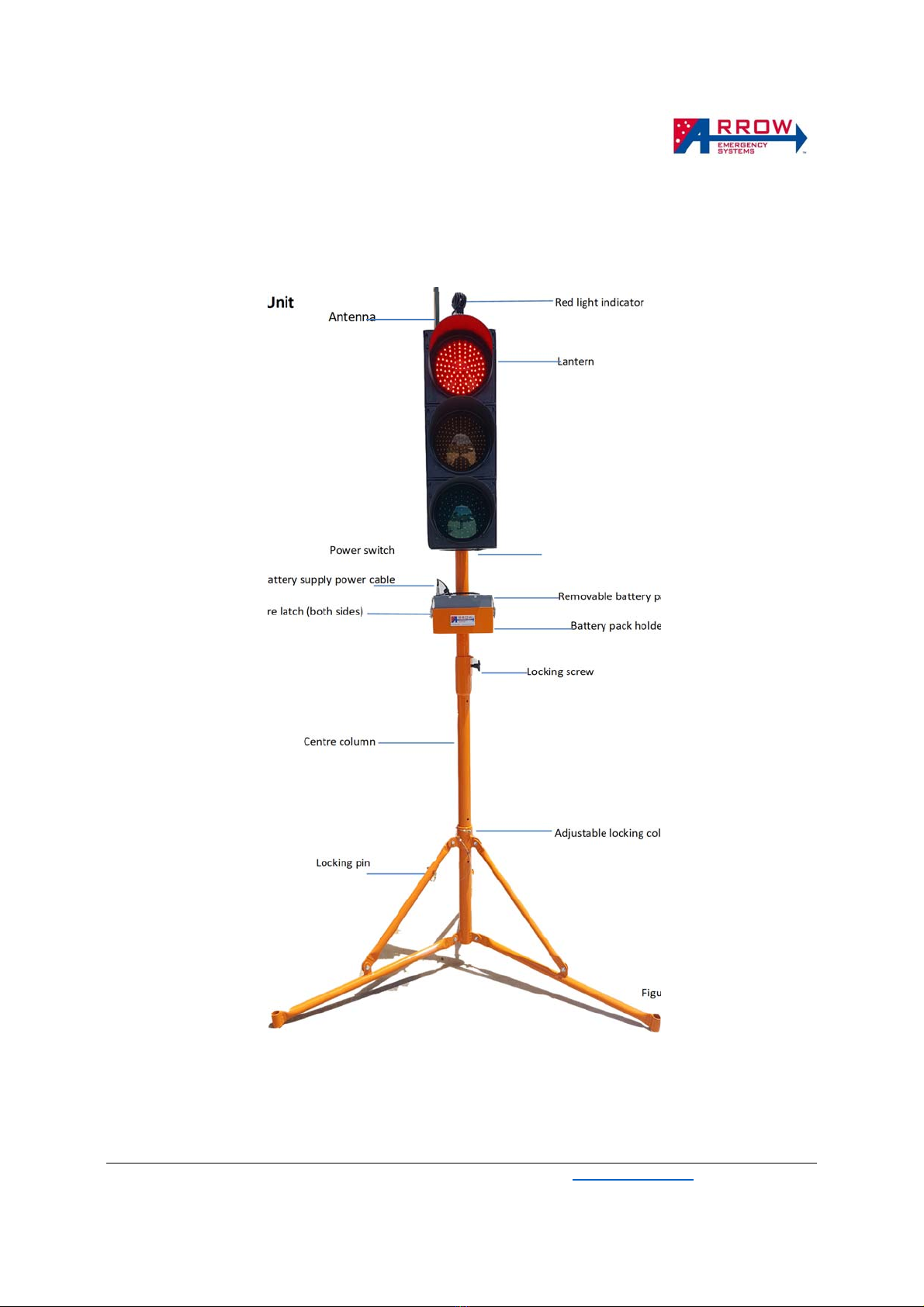
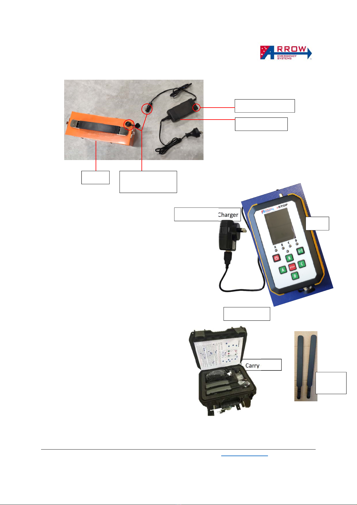
eSTOP™ System Components Diagram ............................................................................................................. 4
Safety Considerations ........................................................................................................................................ 6
eSTOP™ System Specifications ........................................................................................................................... 7
Labels ................................................................................................................................................................. 8
Key Features ...................................................................................................................................................... 8
Unit Assembly/On-site Setup ............................................................................................................................. 9
Target Board Assembly .................................................................................................................................... 10
Operational Procedures ................................................................................................................................... 11
eSTOP™ Lantern Unit ................................................................................................................................... 11
Hand Remote Controller X – HRC X ............................................................................................................. 12
Button Press Types .................................................................................................................................. 12
Operational Steps .................................................................................................................................... 13
Pairing the eSTOP™ Handheld Remote Controller (HRC X) to lantern units ................................................... 15
eSTOP Auto ...................................................................................................................................................... 17
Activate Auto Mode..................................................................................................................................... 17
Setup Auto and Timing ................................................................................................................................ 17
GUI screens ...................................................................................................................................................... 18
Powered Off screen ..................................................................................................................................... 18
Battery Status screen................................................................................................................................... 18
Home Screen ............................................................................................................................................... 18
User manual – eSTOP DVR camera system ..................................................................................................... 19
Batteries - Care, Safe Handling and Charging ................................................................................................... 23
Maintenance of the eSTOP™ ............................................................................................................................ 25
Troubleshooting .............................................................................................................................................. 25
Repairs & Servicing .......................................................................................................................................... 26
Safe Transportation of the eSTOP™ ................................................................................................................. 26
Material Life ..................................................................................................................................................... 26
Warranty .......................................................................................................................................................... 26

eSTOP™ Operations & Service Manual
Arrow Emergency Systems | 17 Bailey Court Brendale Q 4500 | P: (07) 3881 3302 | www.arrowes.com.au Page | 4
eSTOP™ System Components Diagram
eSTOP™ Lantern Unit
Red light indicator
Lantern
Power switch
Battery supply power cable
Removable battery pack
Battery secure latch (both sides)
Battery pack holder
Locking screw
Centre column
Adjustable locking column
Locking pin
Legs
Figure 1
Antenna

eSTOP™ Operations & Service Manual
Arrow Emergency Systems | 17 Bailey Court Brendale Q 4500 | P: (07) 3881 3302 | www.arrowes.com.au Page | 5
Lantern battery pack and charger
eSTOP™ Handheld Remote Controller (HRC)
Equipment Contents
1. 2 eSTOP™ lantern units
2. 2 tripod legs + battery holder
3. 2 lantern battery packs
4. 2 HRC - hand remote control
5. 2 HRC Antenna
6. 2 C4 USB charging cable
7. 1 double USB charge socket
8. 2 battery charger and power socket
9. Carry case
10. User and Service & Operation Manuals
11. 2 target boards (Applicable model only)
Carr
y
Case
Battery
Battery charger
Charging indicator
Push/Pull latching
connector
Dual Port Wall Charger
C4 USB cable
HRC X
HRC
Antenna

eSTOP™ Operations & Service Manual
Arrow Emergency Systems | 17 Bailey Court Brendale
Q
4500 | P: (07) 3881 3302 | www.arrowes.com.au Page | 6
Safety Considerations
The eSTOP™ has been developed as a response to a need for safer working conditions for Traffic Controllers
on job sites. It is designed to remove Traffic Controllers from the hazard zones, but still allowing the Traffic
Controllers to manage traffic movement within the worksite from a safe distance. In order to reduce the
risk to road workers, traffic controllers and road users, the unit must at all times be operated effectively
and consistently by authorized and trained operators.
The eSTOP™ must be operated in accordance with all safety, operation and service instructions contained
in the manufacturer's operation and service manual. It is recommended that all operators read and
understand the manual before operating the eSTOP™. Operators must understand and comply with the
manufacturer's instructions as printed in the manual accompanying each eSTOP™ in conjunction with the
respective Company’s Safe Work Method Statement.
The eSTOP™ should only be operated by a designated, competent operator within the scope of on-site
operation parameters (such as the Company’s Safe Work Method Statement).
The eSTOP™ shall be installed in a suitable location clear of obstructions. An appropriate risk assessment
shall be conducted to ensure the safe and suitable use of the eSTOP™. Examples of factors to consider
when assessing suitable location are: a safe distance from the traffic path, so that wide loads or turning
vehicles will not impact the unit, length of worksite, volume of traffic and topography. The eSTOP™ should
be installed on a stable surface.
The unit including the lanterns (red, yellow and green), yellow light indicator and battery box shall be kept
clean. The equipment shall be handled with care.
The eSTOP™ batteries (both for the hand remote control and the lanterns) shall be fully charged before
operating the unit.
The eSTOP™ has been designed in accordance to DTMR’s (Department of Transport and Main Roads)
specifications, MUTCD guidelines and the MRTS254, ArrowES ISO quality system and ACMA approved. The
eSTOP™ has been approved for use by DTMR. The application of the eSTOP™ shall be in accordance to
these guidelines/standards as well as the respective company’s worksite risk assessment and Safe Work
Method Statements.
Any modifications made to the eSTOP™ (unless by or approved by ArrowES) could compromise the function
of the eSTOP™ and therefore the safe application of the units and voids the warranty of the eSTOP™.

eSTOP™ Operations & Service Manual
Arrow Emergency Systems | 17 Bailey Court Brendale
Q
4500 | P: (07) 3881 3302 | www.arrowes.com.au Page | 7
eSTOP™ System Specifications
Lantern
Operating life of cluster: 100,000 hours
View angel of cluster: 12⁰
Lantern IP rating: IP45
LED Optics IP rating: IP65
Voltage: 12v
Operating amperage: 1.2 A
Battery (rechargeable) 26 A/H Lithium Iron phosphate
Operating Hours (80% DoD) ~20 Hours
Charging time: 4-5 Hours
Operating Temperature Range: -20 to 90⁰ Celsius
Lantern Compliancy AS2144
Comms Range <2km
Hand Remote Controller (HRC)
RF operating frequency: 868-915Mhz
Configuration: up to 4 unit control
IP rating: IP65
Battery (rechargeable): 8 A/H Lithium Polymer
Operating Hours (50% DoD) ~30 Hours
Charging time: 6-8Hours
Operating Current: (Average) 150mA
Sleeping Current: 1mA
Operating Temperature Range: -20 to 85⁰ Celsius
Comms Range <2km
Overall Device
Total mass per device (incl. batt, Target Board): 24kg (allocated to 3 components)
Top lantern weight (max lifting weight): 14kg
Tripod leg footprint radius: 0.80m
Wind loading – no sandbag base: ~40km/h
Wind loading – 3 sandbag/leg ~50kg: ~100km/h
Dimensions
Maximum working height: 2900 cm
Minimum working height: 2600 cm
Dimensions when stored: 1710 mm x 480mm x 370mm
Base width, fully extended: 1600 mm diameter
Lantern height: 770 mm
Lantern width: 270 mm
Lantern depth: 170 mm

eSTOP™ Operations & Service Manual
Arrow Emergency Systems | 17 Bailey Court Brendale
Q
4500 | P: (07) 3881 3302 | www.arrowes.com.au Page | 8
Labels
Key Features
The eSTOP™ is the first Electronic Single Traffic Operator Portable system of its kind. Designed to remove
the Traffic Controllers from the hazard zone, the key features of the eSTOP™ system are:
• Traffic Controllers operate from a safe distance
• Communication range of 2km in line of sight
• Can be implemented anywhere a stop/slow baton would normally be used
• Can be operated with one controller whilst the other takes a break or is on rotation as the HRC
can control up to 4 Lanterns
• Fail safe features - ensure no two green lights can be on at the same time, low battery, tilt and
lantern fault warnings
• Environmentally robust, light weight, three piece assembly, adjustable height
• Small Hand Remote Control (IP65)
• Hand Remote Control mimics traffic lantern states in real time
• Wind load up to 100km/hr when used as per manufacturer’s guidance
Hand control
identification
number is
located at
the back
base as
shown
here
eSTOP™ identification
number is located at
the base of the
lantern as shown here

eSTOP™ Operations & Service Manual
Arrow Emergency Systems | 17 Bailey Court Brendale
Q
4500 | P: (07) 3881 3302 | www.arrowes.com.au Page | 9
Unit Assembly/On-site Setup
A B C D
Pull spring pin to release
leg
Extend legs out by pushing
towards the ground Place legs onto a flat surface and
align adjustable locking column
with pin holes to for uneven
surface. (red circle)
Slide pole up and down to
adjust height then release
pin to lock in place
E F G H
Check antenna is
vertical. Use two
hands to lift traffic
lantern onto base
Slide lantern into the center
locking column
Secure with locking screw to
stop lantern from rotating
Insert battery pack into battery
holder
I K L
Lock latches to secure
battery box
Connect power cable.
Connector latches
once pushed in place.
Switch on lantern Unit is ready to operate
with Hand Remote Control
IMPORTANT: ensure eSTOP™ is stable and is weighted down with sandbags prior to operation. One sand bag
per tripod leg is required.

eSTOP™ Operations & Service Manual
Arrow Emergency Systems | 17 Bailey Court Brendale
Q
4500 | P: (07) 3881 3302 | www.arrowes.com.au Page | 10
Target Board Assembly
Target only applies to applicable systems with Target board brackets.

eSTOP™ Operations & Service Manual
Arrow Emergency Systems | 17 Bailey Court Brendale
Q
4500 | P: (07) 3881 3302 | www.arrowes.com.au Page | 11
Operational Procedures
When the units have been assembled.
eSTOP™ Lantern Unit
1. Connect power cable from Lantern to battery box. To switch on the Lantern, push the small green
Power Switch underneath the lantern unit. The green LED light will illuminate when powered on.
The lantern unit will be controlled by its master, the Handheld Remote Controller (HRC) once the
HRC is paired. Note to make sure the antenna on top of the lantern is vertical.
Modes - The unit runs in three modes, the Test Mode, Manual Mode, Auto Mode.
Test Mode – when the unit first powers on, by default is in test mode. In this mode the
HRC can be used to perform lantern test. See HRC procedures for LED test function, each
lantern will light on for 0.5 seconds.
Manual Mode – The unit can be activated (using HRC) to Manual Mode after power- on/LED
test. See HRC procedures for operation functions. When the unit first activates it will flash
Yellow for 5 seconds then default to Red, then halts for 5 seconds before it can be
operated.
Auto Mode – The unit can be activated (using HRC) to Auto Mode after activated to Manual
Mode. See HRC procedures for operation functions. When Auto Mode is activated, the
Yellow lantern may display a countdown status during the red state, to provide feedback
for the motorist when a green state will occur. Lantern State change in Auto Mode is
controlled by the HRC, the Lantern does not change to Green state after the countdown
ends. The HRC must remain running and within range of all Lantern units in Auto Mode.
2. When the lantern unit is on the RED state, a small yellow LED, called the “Red Light Indicator” will
flash. This Red Light Indicator shall be facing the workers on the worksite. It’s purpose is to indicate
to the workers on the jobsite that the traffic lantern is on red. The Red Light Indicator shall NOT
face the motorists.
3. The eSTOP™ Lantern Unit is also fitted with a “Cut-Off Switch”. This is the Power Switch, located
at the base of the lantern. This switch will turn off the lantern instantaneously as required. Must
also be switched of when not in use.
Note: When setting up the eSTOP™, the lanterns shall face away from motorists until the unit is activated for use
to control traffic (Operation Mode).
The lanterns must be in line of sight of the HRC at all time. The HRC is the master, all Lanterns communicates
directly to the HRC only.

eSTOP™ Operations & Service Manual
Arrow Emergency Systems | 17 Bailey Court Brendale
Q
4500 | P: (07) 3881 3302 | www.arrowes.com.au Page | 12
Hand Remote Controller X – HRC X
Button Press Types
Quick press – A Quick press of the buttons (less than 0.5s), use to navigate the GUI. Home,
Wake, Left, Right, Up and Down Button presses are all Short presses. If the GUI
screen is off a short press does not apply.
Firm press – A Firm press of the buttons (more than 0.5s), use to change states of a paired
lantern (A/B/C/D) during manual mode, or test a paired lantern during test mode.
Firm press applies to A, B, C, D and STOP Button.
Long press- A Long press of the buttons (more than 5s), applies to the Power Button for
powering of and powering off.
Antenna
Antenna Socket
GUI (graphic user interface)
Activate/Wake Button
B/Up Button
C/Right Button
STOP/Enter Button
Lantern LED States
Indicator
Power/Home Button
A/Left Button
D/Down Button

eSTOP™ Operations & Service Manual
Arrow Emergency Systems | 17 Bailey Court Brendale
Q
4500 | P: (07) 3881 3302 | www.arrowes.com.au Page | 13
Operational Steps
1. Power On – Long press Power Button for 5 seconds to power on the HRC. During power on the
battery status screen will appear briefly to show the battery status. Refer to Battery Status screen
section for more detail.
2. Home Screen – Once the HRC is powered on the, the GUI Home screen will appear, showing the
current mode, and the paired Lanterns relative to Buttons A/B/C/D and its status. Refer to Home
screen section for more detail.
3. Wait for Comms – If a lantern is paired to a Button, the status of the lantern will be shown next
to the respective Status Indicator [A][B][C][D] on the Home screen. The status will start with “No
Comms” in red text, wait up to 60 seconds for the communication to establish. Once there is
communication the Status will show the lantern battery percentage in Green text/any faults in
Orange text. If there is no comms after 60 seconds, refer to Troubleshoot section, or Pairing
section to un-pair and re-pair.
4. Modes – the HRC may start on any mode depend on the last Mode before power off. Usually the
HRC will start on Test Mode, where a paired lantern can be tested by Firm pressing the respective
paired Button. To activate to another Mode, Quick press the Left or Right buttons to highlight the
Modes button on the Bottom of the home screen. Quick press the Enter button to enter the
Modes screen.
5. Manual Mode – Once the paired lantern are all communicating, and no faults showing on their
status, the system can be activated to Manual Mode by navigating to the Modes screen and
entering the Manual button on the modes screen. Once entered, the screen will return to Home
screen and the Modes will be changed from Test to Manual Mode, and the Lantern start-up
sequence will commence.
6. Start-up - Upon switching from Test Mode to Manual Mode the lantern will flash yellow for 5
seconds, then 4 seconds of steady yellow, then default to red. The HRC will lock for 10 seconds
and all buttons will not work during this time. After 10 seconds the system with the paired
lanterns is in Manual Mode.

eSTOP™ Operations & Service Manual
Arrow Emergency Systems | 17 Bailey Court Brendale
Q
4500 | P: (07) 3881 3302 | www.arrowes.com.au Page | 14
7. Control Traffic Signals - Use the respective paired A/B/C/D buttons and STOP button to operate
the lanterns for traffic control. Use the Green A/B/C/D buttons to switch one or the other signal
to turn green. (Note: in order to turn a signal green one or all signal must be red first). Use the
Red STOP button to change all signals to red. Note: the yellow lantern will activate for 4 seconds
during the transition from green to red, then lock for 5s in all red before changing to green is
allowed. The Lantern LED state indicators reflect the lantern status.
8. Power Saving feature – once the system is in Manual Mode, the power saving feature on the HRC
will activate after 60 seconds, the screen will turn off and the Lantern LED state indicators will
remain on, allowing the lanterns to be operated as normal. If there is a fault the screen will
automatically turn back on, or the screen can be turn on by pressing the Wake button.
9. Auto Mode – If Auto function is switch on (refer to Setup Section to switch on the Auto function),
the system can be activated to Auto Mode after Manual Mode has being activated. This can be
done through the GUI Modes screen. Once Auto mode is activated, the counting GrnT (green
time) and RedT (all red time) is shown on the home screen. The Modes can be activated back to
Manual or Test mode anytime during Auto Mode.
10. Activate Test Mode- the system can be activated to Test Mode in either Manual or Auto Mode,
when activating Test Mode starts, the lanterns will flash yellow for 5 seconds, then switch the
lanterns off.
11. Power Off HRC – the HRC can be powered off anytime, when powered back on the system will
start on the previous Mode before powering off. To avoid unwanted activated when power on, it
is best practice to activate to Test Mode before powering off.
12. Switch off all lantern power and disconnect battery cable before packing up.
Note: While HRC is off pressing “Power” button on the HRC will indicate battery status. In the
event of forced power off is required on the HRC, pressing “Power” and “Wake” button at the
same time forces the HRC to soft reset then powers off.

eSTOP™ Operations & Service Manual
Arrow Emergency Systems | 17 Bailey Court Brendale
Q
4500 | P: (07) 3881 3302 | www.arrowes.com.au Page | 15
Pairing the eSTOP™ Handheld Remote Controller (HRC X) to lantern
units
The eSTOP™ HRC can be paired to any eSTOP Auto lantern units. Once a lantern unit is paired to a HRC
it is stored in memory, they will be automatically synced when powered up and ready for operation.
By default a HRC is paired to 1 lantern unit only. Repairing is not required unless the HRC is pairing to
a different lantern unit, pairing upto 4 lantern unit to 1 HRC, or lanterns has been mixed up and not
knowing which lantern is paired.
It is recommended to begin pairing by un-pairing all lantern units from the HRC, this will reduce
confusion about which lantern unit if already paired previously. Follow the steps below to begin the
process.
HRC X provide a simple GUI for pairing and unpaired any lanterns. Below shows how to navigate from
the Home screen to the Pairing Screen. The pairing shows the 4 respective button to pair/un-pair a
lantern.
Un-pairing lantern units
Un-pairing is required if the HRC is already paired to an unknown
lantern and unable to sync. To do this the HRC must be in test mode.
Then Navigate to the Pairing screen. Once the Pairing screen is opened,
its will show 4 buttons indicating if they are paired or not. If they are
paired, the option to un-pair is provided. If they are not paired, the
option to pair is provided.
It is recommend to un-pair all lantern before re-pairing lanterns, to
avoid confusion.

eSTOP™ Operations & Service Manual
Arrow Emergency Systems | 17 Bailey Court Brendale Q 4500 | P: (07) 3881 3302 | www.arrowes.com.au Page | 16
Pairing eSTOP™ HRC Unit1 (Left side of the HRC)
1. When in test mode attach the C4 USB cable
from the bottom of the HRC X unit to the USB
connector on the base of the eSTOP™ lantern
unit, show on the image.
2. Navigate from Home Screen to Pairing screen.
Then select any button on the Pairing screen to
pair a lantern to. Once pairing is started an interactive pair
menu will start, follow the instructions on the screen to
complete the pairing process.
3. Once a button is paired to a lantern, the Status on the Home screen will go from blank status
information to some information:
Note to allow upto 60 seconds for the paired lanterns to establish communication.
Lantern USB
connector
C4 cable connected
to HRC and lantern.

eSTOP™ Operations & Service Manual
Arrow Emergency Systems | 17 Bailey Court Brendale
Q
4500 | P: (07) 3881 3302 | www.arrowes.com.au Page | 17
eSTOP Auto
Activate Auto Mode - The eSTOP Auto consist of one Handheld
Remote Controller (HRC) and up to 4 eSTOP Auto lantern units where the
yellow lantern also provides a counter display to count down the time
before the traffic lights turns green. The eSTOP Auto powers up into
manual mode just like the standard eSTOP, and can be activated into
Auto mode from manual operational mode by navigating to the Modes
screen and Enter into Auto Mode.
Setup Auto and Timing - An on screen GUI Setup screen is used to program the HRC X to allow the Auto
feature, to enter the Setup screen, the HRC must be in Test Mode, then navigate from the Home screen to the
Setup screen, then use the UP/DOWN button to select the parameter boxes, and LEFT/RIGHT to change the
parameters. Once done move the cursor to the Save button then press Enter to save.
Enabling Auto mode – Which allows the HRC to activate into Auto mode and control the Paired eSTOP Traffic
Lights in a timing cycle.
Green Time – Time set for a lantern to stay green.
All Red Time – Time set for an all red time (usually the time required for a vehicle entering a site to exit the site
safely), red time is total time minus green time. Red time is generally determined by the time it takes for a
vehicle to exit the work site safely.
Enabling Vehicle Actuated - Vehicle actuations allows green time to be extended on the lantern where a
vehicle is detected. The extension is by 1 cycle of green time. If vehicle is remain detected and no vehicle on
the opposite end, the green time will continue extending for up to 5 cycles. (This results in maximum green
time of 5x(set green time). Green extension time will be cut short if there is vehicle detection on the opposite
side.
Enabling Count Down – This allows the lanterns to provide a countdown status feedback to motorist,
indicating the time till next Green state. Note the lantern does not changes to Green state after the
Countdown ends unless there is a command from the HRC to go Green.

eSTOP™ Operations & Service Manual
Arrow Emergency Systems | 17 Bailey Court Brendale
Q
4500 | P: (07) 3881 3302 | www.arrowes.com.au Page | 18
GUI screens
Powered Off screen
When the HRC is powered off, the screen is completely off and no led indicators are on. The
Power Button can be pressed to power on or check the battery status.
Battery Status screen
The Battery Status screen shows the battery status in percentage and the charging
states.
This screen can be switch on for 10 seconds when the HRC is powered off, by pressing
the Power Button.
When the HRC is plugged into a charger the Battery Status screen stays on permantly,
until the charging cable is unplugged.
Home Screen
The Home screen is the normal screen when the HRC X starts up. this screens provides the options to navigate
between different screens through the on screen buttons on the bottom. And show operational status.
The device ID, Battery Status in percentage is shown on top of the
screen.
The current mode is shown on the top of the Status.
If Auto is enabled, the GrnT, and RedT will be shown on the screen, and
starts counting down once activated to Auto Mode.
Each paired Lantern (in respect to a Button A/B/C/D) provides a status.
The status include:
Modes: M – manual, T – Test, A – Auto, N-unknow
Led States: RED, GRN, YEL, Blank
Lantern Battery Status: xx% (55%)
If the HRC is in critical low battery, a “Low Battery Charge Device”
warning message is shown in orange color.

eSTOP™ Operations & Service Manual
Arrow Emergency Systems | 17 Bailey Court Brendale
Q
4500 | P: (07) 3881 3302 | www.arrowes.com.au Page | 19
User manual – eSTOP DVR camera system
Only for applicable eSTOP
eSTOP camera and DVR placement
Figure 1. eSTOP Camera and DVR
Recording
The eSTOP DVR is set up to record automatically when the eSTOP traffic light powers on. There is a 1
minute delay for the DVR to complete startup and start recording.
A Green light under SD status indicates the DVR is recording.
Stop recording
Recording can be stopped by switching off the power or switching the recording off Enable SW as
Front facing camera
Rear facing camera
eSTOP DVR
DVR Status
Recording
enable SW
SD card slot
USB mouse
DVR functions

eSTOP™ Operations & Service Manual
Arrow Emergency Systems | 17 Bailey Court Brendale
Q
4500 | P: (07) 3881 3302 | www.arrowes.com.au Page | 20
shown in figure one.
Adjusting Camera Angle
Figure 2. Camera rotations
Depending on where the eSTOP is placed, the camera can be rotated horizontally and vertically to suit viewing
angle of the traffic.
Using a LCD and DVR video output
Figure 3. DVR output and LCD
By plugging in the LCD to the DVR’s video output connector shown in the figure 3 above, the videos of the
cameras can be viewed live. This allows camera positions to be adjust effectively, video play back and
indications of recording status.
DVR custom setting
While the LCD is plugged in, a USB mouse can also be plugged in to the USB port shown in figure 1. This allows
This manual suits for next models
1
Table of contents
Popular Safety Equipment manuals by other brands

Ultra-safe
Ultra-safe 96305NTM User instruction manual

ABS
ABS P.RIDE manual

Pilz
Pilz PNOZ Ex operating instructions

Essex PB&R
Essex PB&R MR-10022NAA User Reference and Procedures Manual

Guardian
Guardian Diablo 42009CSA instruction manual

Larson Electronics
Larson Electronics HLSW-AE.EX-PMU-ESTP-R1-RED-C3-S-N-W9 instruction manual