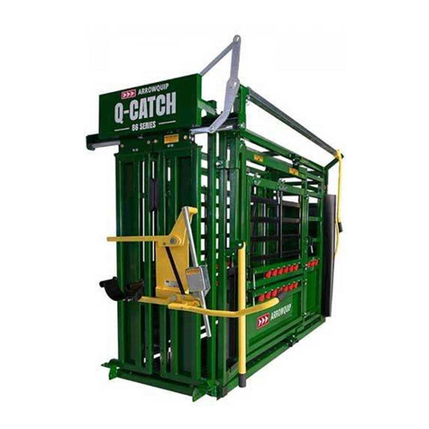
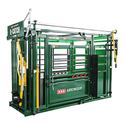
Arrowquip Q-CATCH 86 Series User manual


CONTENTS
Safety Precautions 1
Risk Assessment 2
Transporting the Q-Catch 86 Series Portable Cattle Chute & Alley 2
Operating the Cattle Chute 8
Q-Catch 86 Series Head Gate Assembly 9
Emergency Head Gate Release 10
Recommended Maintenance 11
Wheel Maintenance 12
Portable Jack Conversion 13
Manual Jack to Electric Jack Conversion 13
Electric Jack to Manual Jack Conversion 17
Troubleshooting Guide 20
Warranty 22
Options Maintenance & Safety Precautions 23

PLEASE FOLLOW ALL SAFETY INSTRUCTIONS PROVIDED IN THIS MANUAL
BEFORE OPERATION. ARROWQUIP DOES NOT ACCEPT RESPONSIBILITY FOR
ANY ACCIDENTS OR INJURY WHEN THIS SAFETY MANUAL HAS NOT BEEN
READ IN FULL AND KEPT WITH THE PRODUCT AT ALL TIMES. OPERATORS
OF THIS PRODUCT TAKE AND ACCEPT RESPONSIBILTY FOR ANY HARM OR
INJURY TO THE ANIMAL OR OPERATOR WHEN IT PERTAINS TO HOW THE
EQUIPMENT IS USED AND MAINTAINED.
Please keep this manual for frequent reference and to pass on to new users or owners.
SAFETY PRECAUTIONS
PLEASE FOLLOW ALL SAFETY PRECAUTIONS OUTLINED HEREIN. ANY
HARM TO THE ANIMAL OR INJURY TO THE OPERATOR WHICH OCCURS DUE
TO HOW THE PRODUCT IS OPERATED, OR RESULTING FROM A LACK OF
SAFETY PRECAUTIONS ARE THE SOLE RESPONSIBILITY OF THE OPERATOR.
All farm machinery and equipment is potentially dangerous. Careless use of any Arrowquip
livestock equipment may cause injury or damage to persons, cattle, or property. Arrowquip
has taken precautions in the design and manufacturing of this product to ensure that it is safe
and user-friendly. Therefore, user must assume all responsibility and risk associated with the
possession and use of the equipment.
WARNING: READ BELOW BEFORE OPERATION.
1. Ensure the operator understands the contents of this manual before using the equipment.
2. Donotwearloose-ttedclothing.
3. Ensuretheequipmentisonarm,level,drysurfacethatisfreeofrocksandothertrip
hazards.
4. Do not enter the vet cage until the animal is secured in the head gate.
5. Do not stand in front of the head gate while operator is moving the cattle through the
squeeze chute.
6. DO NOT ALLOW CHILDREN UNDER THE AGE OF 18 NEAR AN OPERATING MACHINE.
7. Follow safe cattle handling procedures in other areas of the yard so that cattle are more
docile.
8. DonotmakeanymodicationstoArrowquipequipment.Non-factorymodicationstothe
equipment can reduce the safety for the operator and livestock.
1
RISK ASSESSMENT
Conduct a risk assessment on procedures for which the equipment is used and establish a safe
work procedure.
1. Ensure all users of the equipment have been inducted and comply with safe working
procedure.
2. Please ensure that there are NO large or hazardous objects inside the equipment that may
cause injury to the animal or operator, or may cause the equipment to malfunction.
3. Make sure that your equipment has been cleared of ALL livestock after use.
4. Some chemicals and medicines can damage powder coat. Take all precautions and wash
after use.
5. Maximum speed 40km/25mph
6. Maintain tire pressure of 80 psi.
7. Check wheel lug nuts after 10, 25, 50 miles of use, ensure torqued to 120 ft. lbs.
a.Thisappliestorsttimeuseandwheelchanges.
TRANSPORTING THE Q-CATCH 86 SERIES
PORTABLE CATTLE CHUTE & ALLEY
WARNING: FOLLOW ALL INSTRUCTIONS OUTLINED HEREIN CAREFULLY TO
ENSURE OPERATOR SAFETY WHEN READYING THE UNIT FOR TRANSPORT.
AFTER EACH USE, DEACTIVATE THE ELECTRICAL
SYSTEM USING THE KILL SWITCH
BEFORE LIFTING THE UNIT, ENSURE IT IS ON LEVEL
GROUND
2

TO LOWER THE UNIT:
1. Use the manual bulldog jack beside the hitch to raise the unit.
Then unhook the unit from towing vehicle.
2. Remove the hitch from the unit.
3. Lower manual bulldog jack beside the hitch until the front of the chute rests on the ground.
3

4. Using the electric controller or manual winder, lift the unit until the tires are 1" from the
ground.
5. Remove tires, and place in a safe place with connector pins.
6. Using the electric controller or manual winder, lower the unit until it rests on the ground.
4

READY FOR USE.
TO RAISE THE UNIT:
1. Using the electric controller or manual winder, lift the unit until the front of the chute rests on
the ground and tires can be installed.
5

2. Install tires and secure with pins.
3. Using the electric controller or manual winder, lower the unit. Continue retracting the jacks
until they are in transport position.
4. Use the manual bulldog jack beside the hitch to raise the unit.
Install the hitch to the unit.
6

5. Connect the unit to the towing vehicle, adjusting the hitch to the proper position for the
vehicle, if necessary.
6. Retract the jack by the hitch and store in transport position.
READY FOR TRANSPORT.
7

OPERATING THE CATTLE CHUTE
REMEMBER SAFETY WHEN OPERATING THE CATTLE CHUTE
1. Ensure all gates and the head gate are closed before the animal enters the chute.
2. Open tail gate for the animal to enter the squeeze chute enclosure.
3. Close tail gate.
4. Open head gate slightly more than the neck size of the animal to tempt the animal to stick
its head through the head gate. When neck of animal is in the correct position, quickly close
theheadgatesecurelyontheanimal’sneck.
5. If required, side squeeze animal and engage head restraint to restrain further movement.
6. If the animal applies excessive pulling pressure on head gate, it is recommended to use the
anti-backing bar behind cattle rump.
7. Conrmanimalissecurelyheldbeforecarryingoutanyhusbandrywork.
8

Q-CATCH 86 SERIES HEAD GATE ASSEMBLY
Your chute will come with the head gate fully assembled and ready for use. However, if you
need to dissemble your head gate for any reason, the following guide will help you to properly
reassemble your chute.
ASSEMBLING THE Q-CATCH MECHANISM
Fit the mechanism parts as shown in the diagram below.
1. Q-CATCH DOOR
2. Q-CATCH TRACK SHAFT
3. LONG HAMMER
4. TOWER CONTROL ARM
5. TOWER SHAFT
6. SHORT HAMMER
7. Q-CATCH CONTROL HANDLE
8. GREASE ZERK
9. Q-CATCH ROLLER
10. Q-CATCH ROLLER BOLT
9

EMERGENCY HEAD GATE RELEASE
Arrowquip squeeze chutes are designed to ensure the safety of both animal and operator. With
proper maintenance and regular lubrication, the head gate will not lock. However, in the
rare event that an animal becomes stuck in the head gate, the following guidelines will ensure
you are able to release your animal quickly and safely
REQUIRED TOOLS
- Screw Driver/Pry Bar
Steps to Release Lock
1. Go to the offside of the chute, to ensure you will not be hit by the head gate handle.
a. If your chute is designed for offside operation, you will need to go to the nearside of
the chute.
2. Place screw driver/pry bar under bottom head gate roller on the outer edge of the door.
a. This is the side with the “L” curve, not the straight side.
3. Insert screw driver/pry bar into the small space above the spring in the head gate
lock plate.
10

4. Tilt the screwdriver/pry bar up and into the head gate roller. This will push down the spring,
releasing the locking mechanism on the head gate door.
RECOMMENDED MAINTENANCE
All Arrowquip Products are made with precision parts to require minimal maintenance. However,
regular maintenance will keep your equipment running smoothly and safely.
1. Keep grease nipple on main control handle greased.
2. Lubricate slam latches, lube bolts, door hinges regularly with WD-40.
Recommended every six months, minimum.
3. Clean bottom head gate door track to prevent dirt build-up.
4. Check mechanism pivot bolts for wear and lubricate or replace, as necessary.
5. Clean and lubricate main locking shaft doors regularly.
6. Inspectforsignsofmechanicaldamageregularly,specicallytogatelatchesand
striker plates, and ensure gates are locking securely.
7. After each use, deactivate the electrical system using the Kill Switch.
• Failure to turn off the kill switch will discharge the battery, and may result in freezing.
THE BATTERIES ON THE NEW PORTABLE HANDLING
SYSTEMS MUST BE CHARGED WITH A 24V AGM BATTERY
CHARGER OR A SMART CHARGER WITH A 24V AGM
SETTING. USING THE WRONG TYPE OF CHARGER CAN
DAMAGE OR BLOW THE BATTERIES COMPLETELY.
11

8. Charge the battery as required with an AGM battery charger or smart charger with an AGM
setting. Battery status should be monitored on the Battery Level Indicator regularly.
• Connect charger to external Battery Lugs. Red: plus, black: minus. Kill switch must be in
‘on’positionforbatteryleveltoshow.
WHEEL MAINTENANCE
It is extremely important to apply and maintain proper wheel mounting torque on your
trailer wheel. Torque is a measure of the amount of tightening applied to a fastener (nut
or bolt) and is expressed as length force. For example, a force of 90 pounds applied at
the end of a wrench on foot long will yield 90 ft. lbs. of torque. A torque wrench is the best
method to assures the proper amount of torque is being applied to a fastener.
Be sure to use only fasteners matched to the cone angle of your wheel – usually 60° or 90°. The
proper procedure for attaching your wheels is as follows:
1. Start all bolts or nuts by hand to prevent cross-threading.
2. Tighten bolts or nuts in the sequence shown for wheel torque requirements.
3. The tightening of the fasteners should be done in stages. Following the recommended
sequence, tighten fasteners per wheel torque requirements diagram.
4. Wheelnuts/boltsshouldbetorquedbeforerstroaduseandaftereachwheelremoval.
Checkandre-torqueaftertherst10miles,25miles,andagainat50miles.Check
periodically thereafter.
Maximum torque level that can be safely applied to the studs are: Stud Size: .5”-20 UNF, class
2A Maximum Torque: 120ft. lbs.
RED
BLACK
BATTERY LEVEL INDICATOR
KILL SWITCH
12

PORTABLE JACK CONVERSION INSTRUCTIONS
TOOLS REQUIRED
- 2x 1/2" Wrench
- 2x 9/16" Wrench
- Hammer
- 5/16 Punch
- Cordless Drill
- 5/16 Drill Bit
- Forklift
- Straps
MANUAL JACK TO ELECTRIC JACK CONVERSION
1. Remove the inside bolts from the top and bottom chain cover plates, and loosen the outer
ones.
Note: A wrench with a long handle is recommended, as this step is a tight t due to
the location of the rolling door.
2. Release the manual handle from transport position, then remove the chain cover by
lifting upwards then out to the side and off.
Note: You must hold the chain to keep it from dropping into the jack.
x2

3. Release the gear by removing the roll pin with a hammer and punch.
4. Remove the nuts, bolts, and washers from the top shaft.
5. Remove the nuts and bolts from the side jacks: two from the top plate and one from the
bottom plate, leaving the bottom bolt in place.
Note: A wrench with a long handle is recommended, as this step is a tight t due to
the location of the rolling door.
14
x2
x2

6. a. Tilt both sides of the jack away from the main frame and remove the shaft.
b. Using the forklift and straps, position the electric box. Secure the box with nuts and bolts.
7. Install the safety switch.
15
x4

8. Place jacks back in upright position, inserting jack shaft into the electric box. Secure with
nuts, bolts, and washers.
Note: Do not overtighten the bolts, or this may cause the gears to grind when jacks
are in use.
9. Secure side jack plates back in place on both sides of the jack with nuts and bolts.
x2
16
x2
x2

ELECTRIC JACK TO MANUAL JACK CONVERSION
1. Remove the nuts and bolts from the side jacks: two from the top plate and one from the
bottom plate, leaving the bottom bolt in place.
Note: A wrench with a long handle is recommended, as this step is a tight t due to
the location of the rolling door.
2. Remove the nuts, bolts, and washers from both sides of the jack shaft.
3. Tilt both sides of the jack away from the main frame and remove the safety switch from the
jack.
x2
x2
x2
17
Other manuals for Q-CATCH 86 Series
2
Table of contents
Other Arrowquip Farm Equipment manuals

Arrowquip
Arrowquip PORTABLE Q-CATCH 74 Series User manual

Arrowquip
Arrowquip THE MAJOR User manual

Arrowquip
Arrowquip Q-CATCH 86 Series User manual

Arrowquip
Arrowquip Q-POWER 107 Series User manual

Arrowquip
Arrowquip Q-POWER 107 Series User manual

Arrowquip
Arrowquip Q-CATCH 5400 User manual

Arrowquip
Arrowquip CALVING PEN User manual

Arrowquip
Arrowquip EASY FLOW CATTLE ALLEY User manual

Arrowquip
Arrowquip Q-CATCH 86 Series User manual

Arrowquip
Arrowquip 1040 User manual