Arteche saTECH TSB-14-H User manual

saTECH TSB-14-H/V
saTECH TSB-14-P-H/V

The test block manual contains instructions for
installation, commissioning and operation.
However, the manual cannot cover all
conceivable circumstances or include detailed
information on all topics.
In case of questions or specific problems do
not take any action without proper
authorization.
Please contact the technical sales of Arteche
and request the necessary information.
All agreements and commitments, legal
relationships and obligations of Arteche Smart
Grid SL including settlements of warranties,
they result solely from the applicable purchase
contract, which is not affected by the contents
of the manual.
All trade names and registered trademarks
mentioned in this document or not, are the
property of their owners.
This manual is for informational purposes and
is subject to change without notice.
651601931
Rev.: 1.2
I.R.: V03
Date: 12/07/2016
© Electrotécnica Arteche Smart Grid, S.L.
RESTRICTED USE DOCUMENT.
Total or partial reproduction of this information
without having to do the prior express written
permission is prohibited.
Document subject to change.

INDEX OF CONTENTS
saTECH TSB-14-H/V | saTECH TSB-14-P-H/V | Rev.: 1.2
3
Chapter 1. Overview.....................................................................................................4
Chapter 2. Cautions .....................................................................................................6
Chapter 3. Main features..............................................................................................7
Chapter 4. Applicatión .................................................................................................8
Chapter 5. Dimensions, installation and connections ............................................16
Chapter 6. Maintenance.............................................................................................21

TECHNICAL SPECIFICATIONS
saTECH TSB-14-H/V | saTECH TSB-14-P-H/V | Rev.: 1.2
4
Chapter 1. Overview
saTECH TSB 14-H/V (TEST BLOCK)
saTECH TSB-14-P-H/V (TEST PLUG )
These test blocks facilitate secondary testing load of any power system, allowing rapid
monitoring, insulation and testing of the field elements.
The box contains saTECH TSB-14:
Set of cabinet fixing screw
Set of rear block connection screw and earth connections.
Requested Model saTECH TSB-14
TSB-14 front cover
TSB-14-H
TSB-14-V
TSB-14-P-H
TSB-14-P-V

TECHNICAL SPECIFICATIONS
saTECH TSB-14-H/V | saTECH TSB-14-P-H/V | Rev.: 1.2
5
The box contains saTECH TSB-14-P:
saTECH TSB-14-P
TSB-P Protector for transport
Safety symbols:
The following symbols are located on different parts of the equipment and this manual:
Paragraphs marked with this symbol contain information which, if not properly
followed, may cause damage to equipment and / or installation.
Paragraphs marked with this symbol contain information which, if not properly
followed, may cause personal injury or even death.
General Safety instructions:
The installation and operation of the products described in this manual can be
made only by trained personnel who have expertise in substation protection,
automation and control.
Do not disassemble the test block or test plug. Correct installation of internal
parts is critical to warrant the isulation and avoid internal arcs.
The ARTECHE guarantee ceases when, without express authorization of
ARTECHE SMART GRID S.L, external personnel to ARTECHE SMART GRID
S.L. makes any changes or reparation in the product. There are not included
the failures by normal use out of the guarantee period, neither by inappropriate
use, carelessness or negligence of the user.

TECHNICAL SPECIFICATIONS
saTECH TSB-14-H/V | saTECH TSB-14-P-H/V | Rev.: 1.2
6
Chapter 2. Cautions
1º-. It’s absolutely necessary to connect the equipment to earth according with the information
defined on chapter 5.
It’s absolutely necessary to connect the equipment to earth according with the
information defined on chapter 5.
2º-. To guarantee the correct operation of the test plug and extend his useful life it is
recommended to clean the fingers periodically for possible metal deposition in the plastic zone
of disruption, which may bring on to a reduction of electrical rigidity and insulation.
3º-. In the case that the customer wanted to make a new dielectric verification , these were
carried out according to point 10.6.4.3.7 of the IEC60255-27 standard (2014), 75% of the value
of dielectric strength established.
4º-. The test blocks are electrical equipment. Therefore, wrong installation or wrong
connection can lead to malfunction or permanent equipment failure, therefore it is
recommended to follow the instructions listed below:
The assembly of the test block should be done with wires which are not
energized.
The test block must be connected rigidly to the ground.
Check that the secondary windings of the current transformers are grounded
through one of its terminals.
Check that the connections are correctly tightened and that the contact
surfaces are clean.
Check the correct polarity of the connections.
Check the correct external wiring. The secondary of the current transformers
must be wired to intensity terminals: A and B.

TECHNICAL SPECIFICATIONS
saTECH TSB-14-H/V | saTECH TSB-14-P-H/V | Rev.: 1.2
7
ATTENTION. All secondary of a current transformer that is not loaded should
be short-circuited; otherwise, the voltage between open circuit and secondary
terminals can reach dangerous levels, even to destroy the equipment.
Chapter 3. Main features
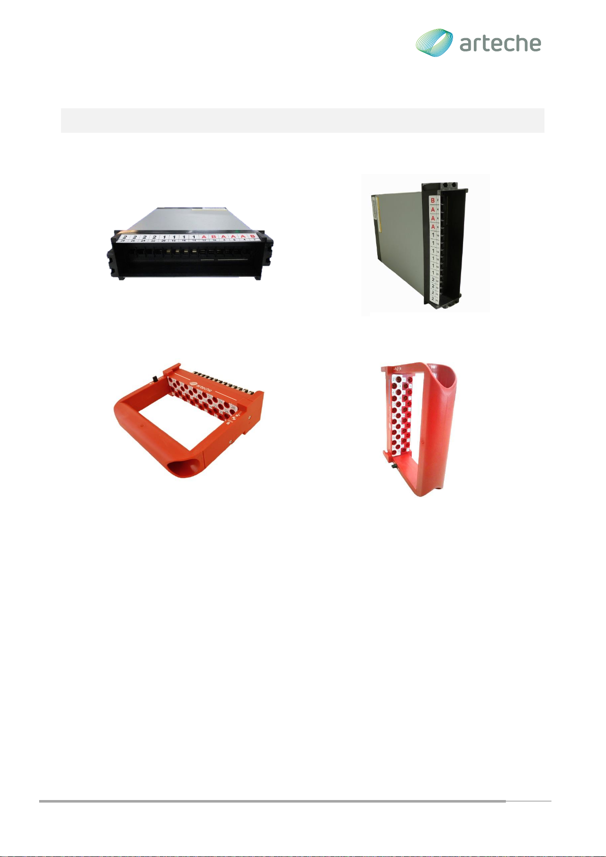
The ARTECHE saTECH test block allows testing the protection relay, safely and easily,
completely insulating the protection relay from the field elements and eliminating any risk to the
user.
The main features are the following:
14 circuits with different configuration (trigger, currents and voltages). This
configuration should be defined prior to the order, because afterwards this
configuration can’t be modified.
Safe for the user, the user will never have access to live parts during insertion or
extraction of the test plug.
Safe insertion sequence, (make before break). The trip circuits are opened in the
first place, avoiding undesired operation and later on, the voltage and current circuits
are opened, ensuring that transformer circuits are shorted before opening the current
circuits.
Safe extraction sequence, the defined extraction sequence assures to have
enough time to stabilizing the system. The first step connects the voltage and the
current circuits, later on, the user must act specifically on the test plug before being
able to extract it completely.
Unique test plug for different test block configuration for the same number of
circuits (14).
Installation Orientation, there are two options: vertical and horizontal, the user is
able to choose the installation orientation.

TECHNICAL SPECIFICATIONS
saTECH TSB-14-H/V | saTECH TSB-14-P-H/V | Rev.: 1.2
8
Chapter 4. Applicatión
saTECH TSB
The test block saTECH includes 14 circuits, which can be accessed by removing the front
cover. The front cover guarantees an IP50 and its removal allows access to the internal
circuitry to enable testing operations.
All of these circuits include a contact that is normally closed when the protection relay is in
service.
The circuits can be classified into: trigger, voltage or current.

TECHNICAL SPECIFICATIONS
saTECH TSB-14-H/V | saTECH TSB-14-P-H/V | Rev.: 1.2
9
On the back side of the test block the circuits are identified by numbers and the numbers
surrounded by a circle corresponding to field.
The circuits include a mechanism for ensuring the short current transformers before proceeding
to open the corresponding contact test block. Arteche offers the possibility to select from
various types of shorted, depending on the application. On the front side of the block, you can
see which of those circuits are shorted, apart from identification shown on labels frame. This
identification is visible even when the test plug is inserted.
The user will define what kind of circuit (trigger, voltage or current) wants in each position at the
moment of ordering the test block saTECH TSB-14-H/V. The user should specify also the type
of short circuit required according to the selection table on page 10 models.
During the insertion of the test plug the circuits are ready to be able to test the protection relay,
according to the following sequence:
1. Opening of the trip circuits and signal.
2. Shorting the circuits of the current transformers.
3. Open the circuit of voltage and current.
Once the test plug is inserted, the protection relay is ready for testing; it will not affect the rest
of the system, because it has been insulated.

TECHNICAL SPECIFICATIONS
saTECH TSB-14-H/V | saTECH TSB-14-P-H/V | Rev.: 1.2
10
The field elements are automatically insulated through shorting circuits and opening the voltage
circuits and tripping.
saTECH TSB-14-P-H/V
The test plug TSP-14-P-H/V includes a guides and a poka-yoke system, to make easier the
insertion into the test block in the proper position and ensuring the opening of all contacts, of
the same type simultaneously. Once the test plug is inserted, it can be locked to prevent
involuntary extractions, turning the black buttons of the test block.
There are 28 banana plugs in the test plug, which allow the use of safety banana plugs: 14
banana plugs of 4mm are used for the test injection of the relay protection, and the other 14 to
provide access to field elements.
All the banana plugs of the test plug are identified by a number that corresponds to the same
number in the test block.
When the test plug is inserted into the test block, the user should push it until there is no gap
between the test block and the test plug, in order to guarantee that the retention system is
working during the safety extraction operation. To verify this, two lines have been arranged in

TECHNICAL SPECIFICATIONS
saTECH TSB-14-H/V | saTECH TSB-14-P-H/V | Rev.: 1.2
11
Example test plug incorrectly inserted
the plug. Once they are aligned with the framework of the block, they will help us to check
visually whether the plug is properly inserted or not.
Example test plug correctly inserted
The retention system force to do the extraction of the test plug, with the following sequence:
First phase:
1. Connect the current and voltage circuits
2. Opening of the short circuit current transformers
Second phase:
3. Connecting the trigger circuitry.
If the test plug has been previously blocked, it will be necessary to act in the retention system
of the test plug, before move to the second phase. The retention system works turning the
black buttons of the test plug: to the right side to lock it, and to the left side to unlock it.
Reference line

TECHNICAL SPECIFICATIONS
saTECH TSB-14-H/V | saTECH TSB-14-P-H/V | Rev.: 1.2
12
This operation will allow voltage and current values to stabilize after transients during the
connection, and will avoid unwanted tripping during the trigger circuit connection.
During the insertion and the extraction of the test plug don’t occur bounces that could harm the
current transformers.
Click

TECHNICAL SPECIFICATIONS
saTECH TSB-14-H/V | saTECH TSB-14-P-H/V | Rev.: 1.2
13

TECHNICAL SPECIFICATIONS
saTECH TSB-14-H/V | saTECH TSB-14-P-H/V | Rev.: 1.2
14
TECHNICAL SPECIFICATIONS
Technical data
Dielectric strength
IEC 60255-27
saTECH
TSB & TSB-P
IEC 60255-5
2kV between input and output contacts
2kV open contacts, test plug inserted
5 kV rms for 1 minute between all terminals
connected together and the ground terminal
2 kV rms for 1 minute between any pair of contacts,
including contacts adjacent
Step current
saTECH TSB
saTECH TSB-P
IEC 60947-7-1
All circuits 20A allow continuously or 400A for 1s
All circuits 10A allow continuously or 250A for 1s.
Maximum operating voltage
saTECH TSB & TSB-P
300 volts ac or dc continuously
IEC 60255
Environmental conditions
Temperature
Storage -25 ° C to + 70 ° C
operation –25°C a +55°C
IEC 60068-2-1 Cold
IEC 60068-2-2 Dry heat
Humidity
IEC 60068-2-78
56 days a 93% Relative Humidity and +40°C
Enclosure protection
IEC 60529-1:
TSB with front cover IP50
TSB without front cover IP20
TSB-P connected IP20
mechanical characteristics
Vibration
60255-21-1 IEC Class II
60255-21-2 IEC Class II
saTECH TSB-14 Back view

TECHNICAL SPECIFICATIONS
saTECH TSB-14-H/V | saTECH TSB-14-P-H/V | Rev.: 1.2
15
MODEL SELECTION
1-. Horizontal position (Reading from right to left)
* The shorting circuits must be placed in a row, e.g.:
2-. Vertical position (Reading
from top to bottom)

TECHNICAL SPECIFICATIONS
saTECH TSB-14-H/V | saTECH TSB-14-P-H/V | Rev.: 1.2
16
Chapter 5. Dimensions, installation and connections
DIMENSIONS
CUT OUT
45mm
TSB-14-111111ABAAAB
Net weight: 1800 gr
Gross weight: 2500 gr
Package: 320 x 250 x 440
TSB-P
Net weight: 600 gr
Gross weight: 1350 gr
Package: 320 x 250 x 440

TECHNICAL SPECIFICATIONS
saTECH TSB-14-H/V | saTECH TSB-14-P-H/V | Rev.: 1.2
17
ASSEMBLY AND INSTALLATION
There are two options for the installation of theTest Block: horizontally and vertically. The
installation of equipment will be made according to the following indications:
In the vertical option, the odd circuits (field) must be located in the right side and the numbers
disposition will be top down.
In the horizontal option, the odd circuits (field) must be at the bottom and the pairs at the top.
The connection of the Test Plug is conditioned by the installation of the Test Block, because it
has a poka-yoke for the correct insertion. The connection of the Test Plug would be made in
the following way:
Vertical option
Horizontal option
Horizontal option
Vertical option

TECHNICAL SPECIFICATIONS
saTECH TSB-14-H/V | saTECH TSB-14-P-H/V | Rev.: 1.2
18
177.8mm
51,6mm
Screw and washers: The wiring operation will be performed with the screws supplied
with each equipment.
Tools needed: 6mm hex wrench tube.
Rear connection:
1. Maximum number of ring terminals that can be connected: 2.
2. Cable up to 4mm2 or 12 AWG.
3. Maximum outer diameter of annular connector: 9mm.
4. With block-type tests are supplied Phillips head M4 screws.
5. The maximum torque for the screws is 2.5N.
Earth connection.
After the test block is placed in the cabinet, the earth connection must be made. The
saTECH TSB. Has two earth connections, one of them has to be done. In order to
guarantee the IP protection, both grounding screws should be fixed. The wiring and
earth connection screw set are included with the test block.
Earth connection

TECHNICAL SPECIFICATIONS
saTECH TSB-14-H/V | saTECH TSB-14-P-H/V | Rev.: 1.2
19
CONNECTIONS
The maximum and minimum dimensions of annular connectors recommend to be used in the
back of the test block are:

TECHNICAL SPECIFICATIONS
saTECH TSB-14-H/V | saTECH TSB-14-P-H/V | Rev.: 1.2
20
APPLICATION EXAMPLE
This manual suits for next models
3
Table of contents
Other Arteche Test Equipment manuals