3Aruba 203H Access Point | Installation Guide
One of the following power sources:
IEEE 802.3af-compliant Power over Ethernet (PoE)
source.
For AP-203H only:
Aruba Controller provisioned on the network:
Layer 2/3 network connectivity to your access point
One of the following network services:
Aruba Discovery Protocol (ADP)
DNS server with an “A” record
DHCP Server with vendor-specific options
Verifying Pre-Installation Connectivity
Before installing access points in a network environment,
make sure that they are able to locate and connect to the
controller after power on.
Specifically, you must verify the following conditions:
When connected to the network, each access point is
assigned a valid IP address
Access points are able to locate the controller
Refer to the ArubaOS Quick Start Guide for instructions on
locating and connecting to the controller.
Identifying Specific Installation Locations
Use the access point placement map generated by Aruba’s RF
Plan software application to determine the proper
installation location(s). Each location should be as close as
possible to the center of the intended coverage area and
should be free from obstructions or obvious sources of
interference. These RF absorbers/reflectors/interference
sources will impact RF propagation and should have been
accounted for during the planning phase and adjusted for in
RF plan.
Identifying Known RF Absorbers, Reflectors and
Interference Sources
Identifying known RF absorbers, reflectors, and interference
sources while in the field during the installation phase is
critical. Make sure that these sources are taken into
consideration when you attach an access point to its fixed
location. Examples of sources that degrade RF performance
include:
Cement and brick
Objects that contain water
Metal
Microwave ovens
Wireless phones and headsets
Installing the Access Point
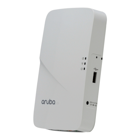
The 203H access point is designed to mount into a variety of
electrical gang boxes.
1. Remove the existing data wall plate (if applicable).
2. Remove any existing RJ45 connectors (typically snap-in) or
cut/remove the UTP cable.
3. Use a short Ethernet cable (sold separately), connect the
E0 port to an RJ45 connector, or crimp an RJ45 plug (not
supplied) on the cable and insert into the E0 port. Do the
same for the pass though port, if used.
4. Depending on the types of your wall boxes, you can
choose different holes from the mounting bracket to
attach the bracket onto the wall box (see Figure 4 and
Figure 5).
The applicable standards for the wall boxes are:
IEC 60670-1, GB17466, BS4662 and DIN49073 for
Worldwide
ANSI/NEMA OS 1 and OS 2 for US
Figure 4 Securing Bracket to US Single Gang Wall Box
Figure 5 Securing Bracket to Worldwide Single Gang Wall Box
5. Align the mounting holes of the mounting bracket with
the mounting holes on the wall box. Insert the two
included machine screws and tighten them to secure the
mounting bracket.
Aruba Networks, Inc., in compliance with governmental
requirements, has designed the 203H access points so that
only authorized network administrators can change the
settings. For more information about access point
configuration, refer to the ArubaOS Quick Start Guide /Aruba
Instant Quick Start Guide and ArubaOS User Guide/Aruba
Instant User Guide.
The instructions in this section are applicable to the AP-
203H only.
Service to all Aruba Networks products should be
performed by an AMCP certified technician or similar.
