Aruba IAP-274 User manual

IAP-270 Series Outdoor Access Point
Installation Guide
0511605-04 |December 2017 1
The Aruba IAP-274 and IAP-275 are environmentally hardened, outdoor rated, dual-radio IEEE 802.11ac
wireless access points. These access points use MIMO (Multiple-in, Multiple-out) technology and other
high-throughput mode techniques to deliver high-performance, 802.11ac 2.4 GHz and 5 GHz functionality
while simultaneously supporting existing 802.11a/b/g/n wireless services.
IAP-270 Series Operations
Wireless transceiver
Wireless access point (IEEE 802.11 a/b/g/n/ac)
Wireless air monitor (IEEE 802.11 a/b/g/n/ac)
Protocol-independent networking functionality
Compatibility with IEEE 802.3at PoE
Guide Overview
"IAP-270 Series Hardware Overview" on page3 provides a detailed hardware overview of the IAP-274
and IAP-275.
"Before You Begin" on page7 provides key questions to ask and items to consider when deploying an
outdoor wireless network.
"Installing the AP" on page8 describes the multi-step process for a successful installation and
deployment of the IAP-274 and IAP-275.
"Safety and Regulatory Compliance" on page14 provides an overview of safety and regulatory
compliance information.
Package Contents
IAP-274 or IAP-275 Access Point
Cable Glands x2
Copper Lug x1
M4x6 Screw x1
USB Console Cable
Aruba Instant Quick Start Guide
Installation Guide (this document)
The IAP-270 Series requires Aruba Instant 4.1 or later.
The weatherproof caps for Ethernet, Console, and power interfaces are connected to the AP, not loose in the
package.

2IAP-270 Series Outdoor Access Point | Installation Guide
Mounting kits for use with the IAP-270 Series access points are sold separately. Contact your Aruba sales
representative for details.
Inform your supplier if there are any incorrect, missing, or damaged parts. If possible, retain the carton, including
the original packing materials. Use these materials to repack and return the unit to the supplier if needed.

IAP-270 Series Outdoor Access Point | Installation Guide 3
IAP-270 Series Hardware Overview
Figure 1 IAP-274 Front View (Aesthetic Cover Removed)
Figure 2 IAP-275 Front View
LED
The IAP-270 Series is equipped with one LED that indicates the system status of the AP.
System LED
The antenna connectors of IAP-274 are covered by an aesthetic cover in the package. The aesthetic cover can be
removed when necessary.
System LED

4IAP-270 Series Outdoor Access Point | Installation Guide
Table 1 IAP-270 Series LED Meanings during Boot Up
Table 2 IAP-270 Series LED Meanings during Operation
Figure 3 IAP-274 Rear View
LED Color/State Meaning
System LED Off No power to AP
Red Initial power-up
Green - Flashing AP booting
Green - Steady AP ready and 1000Mbps Ethernet link established. The LED turns
off after 1200 seconds
Green - Yellow, 6 seconds
period AP ready and 10/100Mbps Ethernet link established. The LED
turns off after 1200 seconds
LED Color/State Meaning
System LED Solid Red General fault
One blink off every 3
seconds Radio 0 fault (5 GHz)
Two quick blink off 0.5
seconds apart cycled every
3 seconds
Radio 1 fault (2.4GHz)
AC Power Interface
LAN Port
WAN Port
Grounding Point
USB Console Port and Reset button

IAP-270 Series Outdoor Access Point | Installation Guide 5
Figure 4 IAP-275 Rear View
USB Console Port
The USB Micro-B console port allows you to connect the AP to a terminal or a laptop for direct local
management. Use the included USB console cable to connect the AP. You can download the necessary
driver for USB-UART adapter from support.arubanetworks.com under the Tools & Resources tab.
Use the following setting to access the terminal:
Ethernet Ports
IAP-270 Series is equipped with two10/100/1000Base-T (RJ-45) Gigabit Ethernet ports (WAN and LAN port)
for wired network connectivity. The WAN port supports 802.3at Power over Ethernet (PoE), accepting 48
VDC (nominal) as a standard defined Powered Device (PD) from a Power Sourcing Equipment (PSE) such
as a PoE midspan injector.
These ports have RJ-45 female connectors with the pin-outs shown in Figure 5.
Figure 5 Gigabit Ethernet Port Pin-Out
Reset Button
The reset button can be used to return the AP to factory default settings. To reset the AP:
Table 3 Console Settings
Baud Rate Data Bits Parity Stop Bits Flow Control
9600 8 None 1 None
AC Power Interface
LAN Port
WAN Port
Grounding Point
USB Console Port and Reset button
1000Base-T Gigabit
Ethernet Port
RJ-45 Female
Pin-Out
Signal Name
1
2
3
4
5
6
7
8
BI_DC+
BI_DC-
BI_DD+
BI_DD-
BI_DA+
BI_DA-
BI_DB+
BI_DB-
Function
Bi-directional pair +C, POE Positive
Bi-directional pair -C, POE Positive
Bi-directional pair +D, POE Negative
Bi-directional pair -D, POE Negative
Bi-directional pair +A, POE Negative
Bi-directional pair -A, POE Negative
Bi-directional pair +B, POE Positive
Bi-directional pair -B, POE Positive

6IAP-270 Series Outdoor Access Point | Installation Guide
1. Power off the AP.
2. Press and hold the reset button using a small, narrow object, such as a paperclip.
3. Power-on the AP without releasing the reset button. The system LED will flash within 5 seconds.
4. Release the reset button.
The system LED will flash again within 15 seconds indicating that the reset is completed. The AP will now
continue to boot with the factory default settings.
AC Power Interface
The IAP-270 Series is capable of AC power in the range of 100 - 240 VAC. The power cord or power
connector kit is sold separately.
Grounding Point
Always remember to protect the AP by installing grounding lines. The ground connection must be complete
before connecting power to the AP enclosure.
Figure 6 IAP-274 and IAP-275 Top View
At the top of the IAP-270 Series, the solar shield with the mounting holder is fixed onto the AP before
shipping from the factory.
Figure 7 IAP-274 Bottom View
Solar Shield
Mounting Holder
With Aesthetic Cover Aesthetic Cover Removed

IAP-270 Series Outdoor Access Point | Installation Guide 7
Figure 8 IAP-275 Bottom View
External Antenna Connectors
The IAP-274 is equipped with six N-type female connectors.for external antenna. The connectors are
labeled 2G0, 2G1, 2G2, 5G0, 5G1 and 5G2, and correspond to 2.4/5Ghz radio chains 0,1, and 2.
Air Vent
The bottom of the IAP-270 Series has an air vent to balance the pressure and humidity inside and outside
the AP. It also allows air exchange between the AP and the environment in a controlled way that doesn’t
allow water to get into the AP.
Before You Begin
Air Vent
Please install the external antennas according to the manufacturer’s instruction and connect the antennas to the N-
type female antenna connectors on the IAP-274 access point.
!
External antennas for this device must be installed by an Aruba Certified Mobility Professional (ACMP) or other
Aruba-certified technician, using manufacturer-approved antennas only.
The Equivalent Isotropically Radiated Power (EIRP) levels for all external antenna devices must not exceed the
regulatory limit set by the host country/domain.
Installers are required to record the antenna gain for this device in the system management software.
Les antennes externes pour cet appareil doivent être installées par un professionnel de la mobilité certifié Aruba
(ACMP) ou un autre technicien certifié Aruba, en utilisant uniquement des antennes approuvées par le fabricant.
Les niveaux équivalents de puissance à rayonnement isotrope (EIRP) pour tous les périphériques d'antenne
externe ne doivent pas dépasser la limite réglementaire définie par le pays hôte / domaine.
Les installateurs doivent enregistrer le gain d'antenne pour cet appareil dans le logiciel de gestion du système.
!
FCC Statement: Improper termination of access points installed in the United States (non-US model Regulatory
Domain model/s) will be in violation of the FCC grant of equipment authorization. Any such willful or intentional
violation may result in a requirement by the FCC for immediate termination of operation and may be subject to
forfeiture (47 CFR 1.80).

8IAP-270 Series Outdoor Access Point | Installation Guide
Identifying Specific Installation Locations
You can mount the IAP-270 Series access point on a wall or pole. Use the AP placement map generated by
Aruba’s RF Plan software application to determine the proper installation location(s). Each location should
be as close as possible to the center of the intended coverage area and should be free from obstructions or
obvious sources of interference. These RF absorbers/reflectors/interference sources will impact RF
propagation and should have been accounted for during the planning phase and adjusted for in RF plan.
Identifying Known RF Absorbers/Reflectors/Interference Sources
Identifying known RF absorbers, reflectors, and interference sources while in the field during the
installation phase is critical. Make sure that these sources are taken into consideration when you attach an
AP to its fixed location. Examples of sources that degrade RF performance include:
Cement and brick
Objects that contain water
Metal
Microwave ovens
Wireless phones and headsets
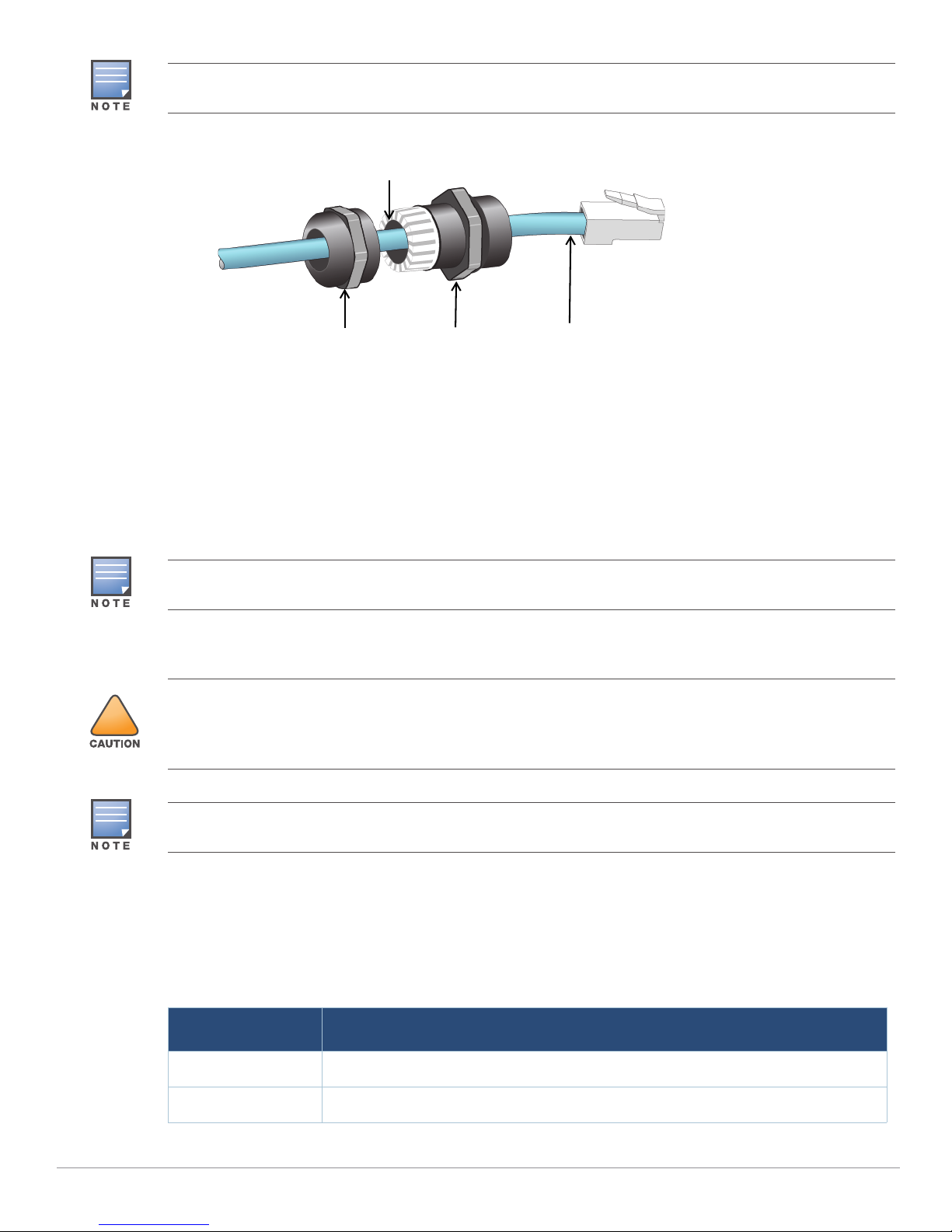
Installing the AP
!
EU Statement:
Lower power radio LAN product operating in 2.4 GHz and 5 GHz bands. Please refer to the Aruba Instant User
Guide for details on restrictions.
Produit réseau local radio basse puissance operant dans la bande fréquence 2.4 GHz et 5 GHz. Merci de vous
referrer au Aruba Instant User Guide pour les details des restrictions.
Low Power FunkLAN Produkt, das im 2.4 GHz und im 5 GHz Band arbeitet. Weitere Informationen bezlüglich
Einschränkungen finden Sie im Aruba Instant User Guide.
Apparati Radio LAN a bassa Potenza, operanti a 2.4 GHz e 5 GHz. Fare riferimento alla Aruba Instant User Guide
per avere informazioni detagliate sulle restrizioni.
Aruba Networks, Inc. in compliance with governmental requirements, has designed the IAP-270 Series such that
only authorized network administrators can change configuration settings. For more information about AP
configuration, refer to the Aruba Instant Quick Start Guide and Aruba Instant User Guide.
!
Access points are radio transmission devices and as such are subject to governmental regulation. Network
administrators responsible for the configuration and operation of access points must comply with local broadcast
regulations. Specifically, access points must use channel assignments appropriate to the location in which the
access point will be used.
Service to all Aruba products should be performed by trained service personnel only.

IAP-270 Series Outdoor Access Point | Installation Guide 9
Using the Mounting Kits
The IAP-270 Series can be installed on a wall or attached to a pole by using mounting kits:
Grounding the AP
The grounding must be completed before powering up the AP. The grounding wire should be #8 AWG.
1. Peel the cover of one end of the grounding wire and place the bare grounding wire into the included
copper lug, and press firmly with the crimping pliers.
2. Fasten the copper lug to the grounding hole on the AP with the included M4 x6 screw as shown in Figure
9.
Figure 9 Grounding the AP
Connecting the Ethernet Cable
To connect the Ethernet cable to the AP, perform the following steps using the cable glands that ships with
your AP.
Table 4 Applicable Mounting Kits for IAP-270 Series
Part Number Description
AP-270-MNT-V1 Long mounting kit for wall and vertical pole mounting, 300 mm from vertical mounting
asset.
AP-270-MNT-V2 Short mounting kit for wall and vertical pole mounting, 75 mm from vertical mounting
asset.
AP-270-MNT-H1 Mounting kit for hanging from inclined or horizontal structure.
The IAP-270 Series access point does not ship with any mounting kits. These mounting kits are available as
accessories.and must be ordered separately.
For installation instructions on AP-270-MNT-V1, AP-270-MNT-V2 and AP-270-MNT-H1, please refer to the AP-
270-MNT-V1 Installation Guide, AP-270-MNT-V2 Installation Guide and AP-270-MNT-H1 Installation Guide
respectively.
Failure to use the included Ethernet cable glands can lead to connectivity and POE issues.

10 IAP-270 Series Outdoor Access Point | Installation Guide
Figure 10 Installing a Cable Gland
1. Slide the sealing nut over the cable (without the RJ45 connector attached to the end).
2. Slide the clamping ring over the cable.
3. Using a crimping tool, attach the shielded RJ45 connector to the end of the cable.
4. Remove the weatherproof cap on the Ethernet port.
5. Insert the RJ45 connector to the Ethernet port.
6. Screw the clamping ring onto the Ethernet port.
7. Screw the sealing nut onto the clamping ring.
Connecting the Power Cable
The IAP-270 Series product offering offers two ways to connect the unit to AC power. Two power cord
variants are offered and a connector kit that allows the customer to assemble their own cable if the
standard offering does not meet deployment needs.
The applicable SKUs for these options are:
The cable is not included and must be purchased separately. Purchase a suitable UV-resistant, outdoor rated, CAT
5E or better RJ45 cable for use with the AP.
Sealing Nut Clamping Ring CAT 5E or Better Cable
Seals
The seals inside the clamping ring by factory default is applicable for cables with 5-8.5 mm diameter. In the cable
gland kit, another seals is provided for use with the cables with 7-10 mm diameter.
!
Installation and service of Aruba products should be performed by Professional Installers in a manner that is
consistent with the electrical code in force in the jurisdiction of deployment. In many countries this will require a
licensed electrician to perform this operation. In Japan, this is a Certified Electrician by Ministry of Economy, Trade,
and Industry.
The IAP-270 Series does not ship with any power cables. These are available as accessories and should be ordered
separately.
Table 5 SKUs for Powering Options
Part Number Description
PC-OD-AC-P-NA Weatherproof AC power cable(5m), North America version
PC-OD-AC-P-INT Weatherproof AC power cable(5m), International (EU) version

IAP-270 Series Outdoor Access Point | Installation Guide 11
The difference between the NA and INTL part variants is the color coding of the conductors.
The North American cable uses Black (Hot), White (Neutral), and Green (Ground).
The INTL part follows the international schema of Brown (Hot), Blue (Neutral) and Yellow/Green
(Ground)
Best Practice for Outdoor Connection to AC Mains
In all circumstances and with any outdoor infrastructure the recommended practice is to connect to AC
mains in an order grade weather protected junction box. This needs to be implemented by a qualified
resource in a manner that is consistent with the electrical code in force in the jurisdiction of deployment. In
many countries this will require a licensed electrician to perform this operation.
In Japan, this would is a Certified Electrician by Ministry of Economy, Trade and Industry.
The use of plugs with infrastructure equipment is suitable only for temporary installs where nuisance
tripping of GFI plugs is considered tolerable. Should it be desired to attach a plug to the cable assemblies
then the installer is expected to follow all directions provided with the plug end in a fashion consistent with
local electrical code.
Use of the CKIT-OD-AC-P
Assembly instructions for this part are shipped with the part. All instructions must be followed to ensure
proper assembly of the connector onto the cable.
The required specifications for third party cable used with the CKIT solution are as follows:
AC power cable specifications (when using AC connector kit and custom cable): minimum voltage/
current rating 250V/1A, diameter 6-12mm, rated for outdoor use and UV exposure
AC Power Cable Connector PIN OUT
Figure 11 AC power cable connector
Connecting the Power Cable to the IAP-275
1. Remove the weatherproof cap on the power interface.
CKIT-OD-AC-P Weatherproof connector kit for AC power interface
Table 5 SKUs for Powering Options
Part Number Description
!
Please only use included or Aruba specified cables, power cords, AC power supplies and batteries. The power cord
should not be used with other electric equipment than what is specified by Aruba
HotNeutral
Ground

12 IAP-270 Series Outdoor Access Point | Installation Guide
2. Insert the power cable connector into the power interface and hand-fasten the locknut.
Verifying Post-Installation Connectivity
The integrated LEDs on the AP can be used to verify that the AP is receiving power and initializing
successfully (see Table 1 and Table 2). Refer to the Aruba Instant Quick Start Guide for further details on
verifying post-installation network connectivity.

IAP-270 Series Outdoor Access Point | Installation Guide 13
Product Specifications
Mechanical:
Device Dimensions (HxWxD)
IAP-274 (without aesthetic cover): 5.5 inches x 9 inches x 9.4 inches (14cm x 23cm x 24cm)
IAP-274 (with aesthetic cover): 7.5 inches x 9 inches x 9.4 inches (19cm x 23cm x 24cm)
IAP-275: 10.6 inches x 9 inches x 9.4 inches (27cm x 23cm x 24cm)
Weight
IAP-274(without aesthetic cover): 5.3 lbs/2.4 kg
IAP-274 (with aesthetic cover): 6lbs/2.7kg
IAP-275: 5.3 lbs/2.4 kg
Electrical
Ethernet
2 x 10/100/1000Base-T auto-sensing Ethernet RJ-45 Interfaces
MDI/MDX
Power over Ethernet (IEEE 802.3at compliant), 48VDC/0.6A
Power
100-240 VAC 50/60 Hz from external AC power source
POE support on WAN port: 802.3at-compliant POE sourcing devices
Environmental
Operating
Temperature: -40ºC to 65ºC (-40ºF to 150ºF)
Humidity: 5% to 95% non-condensing
Storage
Temperature: -40ºC to 70ºC (-40ºF to 158ºF)
For additional specifications on this product, please refer to the data sheet. The data sheet can be found at
www.arubanetworks.com.

14 IAP-270 Series Outdoor Access Point | Installation Guide
Safety and Regulatory Compliance
Aruba Networks provides a multi-language document that contains country-specific restrictions and
additional safety and regulatory information for all Aruba access points. This document can be viewed or
downloaded from the following location: www.arubanetworks.com/safety_addendum
Regulatory Model Name
The following regulatory model names apply to the IAP-270 Series:
IAP-274: APEX0101
IAP-275: APEX0100
FCC
This device is electronically labeled. To view the FCC ID:
1. Log into the controller WebUI
2. Navigate to Maintenance > Controller > About.
FCC Class B Part 15
This device complies with Part 15 of the Federal Communications Commission (FCC) Rules. Operation is
subject to the following two conditions:
This device may not cause harmful interference.
This device must accept any interference received, including interference that may cause undesired
operation.
This equipment has been tested and found to comply with the limits for a Class B digital device, pursuant to
Part 15 of the FCC Rules. This equipment generates, uses and can radiate radio frequency energy and, if not
installed and used in accordance with the manufacturer’s instructions, may cause interference harmful to
radio communications.
If this equipment does cause interference, which can be determined by turning the equipment off and on,
the user is encouraged to try to correct the interference by one or more of the following measures:
Reorient or relocate the receiving antenna.
Increase the separation between the equipment and receiver.
Connect the equipment to an outlet on a circuit different from that to which the receiver is connected.
Consult the dealer or an experienced radio or TV technician for help.
!
Aruba access points must be installed by a professional installer. The professional installer is responsible for
ensuring that grounding is available and it meets applicable local and national electrical codes.
!
RF Radiation Exposure Statement: This equipment complies with FCC RF radiation exposure limits. This
equipment should be installed and operated with a minimum distance of 13.78 inches (35 cm) between the radiator
and your body for 2.4 GHz and 5 GHz operations. This transmitter must not be co-located or operating in
conjunction with any other antenna or transmitter. When operated in the 5.15 to 5.25 GHz frequency range, this
device is restricted to indoor use to reduce the potential for harmful interference with co-channel Mobile Satellite
Systems.
!
Changes or modifications to this unit not expressly approved by the party responsible for compliance could void
the user’s authority to operate this equipment.

IAP-270 Series Outdoor Access Point | Installation Guide 15
EU Regulatory Conformance
Aruba Networks, Inc., hereby declares that the APEX0101 and APEX0100 device models are in
compliance with the essential requirements and other relevant provisions of Directive 1999/5/EC -CE(!).
The Declaration of Conformity made under Directive 1999/5/EC is available for viewing at
www.arubanetworks.com.
Proper Disposal of Aruba Equipment
For the most current information about Global Environmental Compliance and Aruba products, see our
website at www.arubanetworks.com.
Waste of Electrical and Electronic Equipment
Aruba products at end of life are subject to separate collection and treatment in the EU
Member States, Norway, and Switzerland and therefore are marked with the symbol
shown at the left (crossed-out wheelie bin). The treatment applied at end of life of these
products in these countries shall comply with the applicable national laws of countries
implementing Directive 2002/96EC on Waste of Electrical and Electronic Equipment
(WEEE).
European Union RoHS
Aruba products also comply with the EU Restriction of Hazardous Substances
Directive 2011/65/EC (RoHS). EU RoHS restricts the use of specific hazardous
materials in the manufacture of electrical and electronic equipment. Specifically,
restricted materials under the RoHS Directive are Lead (including Solder used in
printed circuit assemblies), Cadmium, Mercury, Hexavalent Chromium, and Bromine. Some Aruba products
are subject to the exemptions listed in RoHS Directive Annex 7 (Lead in solder used in printed circuit
assemblies). Products and packaging will be marked with the “RoHS” label shown at the left indicating
conformance to this Directive.
China RoHS
Aruba products also comply with China environmental declaration requirements and are
labeled with the “EFUP 10” label shown at the left.
10
᳝↦᳝ᆇ⠽䋼ໄᯢ
Hazardous Materials Declaration
᳝↦᳝ᆇ⠽䋼ܗ㋴(Hazardous Substance)
䚼ӊৡ⿄
(Parts) 䪙
3E
∲
+J
䬝
&G
݁Ӌ䫀
&U
⒈㘨㣃
3%%
⒈Ѡ㣃䝮
3%'(
⬉䏃ᵓ
(PCA Boards) hƻƻ ƻ ƻ ƻ
ᴎẄ㒘ӊ
(Mechanical Sub-Assemblies)
hƻƻ ƻ ƻ ƻ
ƻ˖ 㸼⼎䆹᳝↦᳝ᆇ⠽䋼䆹䚼ӊ᠔᳝ഛ䋼ᴤ᭭Ёⱘ䞣ഛ SJ/T11363-2006 ޚ㾘ᅮⱘ䰤䞣㽕∖ҹϟDŽ
Indicates that the concentration of the hazardous substance in all homogeneous materials in the parts is
below the relevant threshold of the SJ/T11363-2006 standard.
h˖ 㸼⼎䆹᳝↦᳝ᆇ⠽䋼㟇ᇥ䆹䚼ӊⱘᶤϔഛ䋼ᴤ᭭Ёⱘ䞣䍙ߎ6-7ޚ㾘ᅮⱘ䰤䞣㽕∖DŽ
Indicates that the concentration of the hazardous substance of at least one of all homogeneous materials
in the parts is above the relevant threshold of the SJ/T11363-2006 standard.
ᇍ䫔ଂП᮹ⱘ᠔ଂѻકᴀ㸼ᰒ⼎կᑨ䫒ⱘ⬉ᄤֵᙃѻકৃ㛑ࣙ䖭ѯ⠽䋼DŽ
This table shows where these substances may be found in the supply chain of electronic information
products, as of the date of sale of the enclosed product.
ℸᖫЎ䩜ᇍ᠔⍝ঞѻકⱘ⦃ֱՓ⫼ᳳᖫᶤѯ䳊䚼ӊӮ᳝ϔϾϡৠⱘ⦃ֱՓ⫼ᳳ
՟བ⬉∴ܗഫ䌈݊ѻકϞ
ℸ⦃ֱՓ⫼ᳳ䰤া䗖⫼ѢѻકᰃѻકݠЁ᠔㾘ᅮⱘᴵӊϟᎹ
The Environment- Friendly Use Period (EFUP) for all enclosed products and their parts are
per the symbol shown here. The Environment- Friendly Use Period is valid only when the
product is operated under the conditions defined in the product manual.

16 IAP-270 Series Outdoor Access Point | Installation Guide
Canadian Statement
Under Industry Canada regulations, this radio transmitter may only operate using an antenna of a type and
maximum (or lesser) gain approved for the transmitter by Industry Canada. To reduce potential radio
interference to other users, the antenna type and its gain should be so chosen that the equivalent
isotropically radiated power (e.i.r.p.) is not more than that necessary for successful communication.
This device complies with Industry Canada licence-exempt RSS standard(s).
Operation is subject to the following two conditions: (1) this device may not cause interference, and (2) this
device must accept any interference, including interference that may cause undesired operation of the
device.
Canadian Caution
This radio transmitter (identify the device by certification number, or model number ifCategory II) has
been approved by Industry Canada to operate with the antenna typeslisted below with the maximum
permissible gain and required antenna impedance foreach antenna type indicated. Antenna types not
included in this list, having a gaingreater than the maximum gain indicated for that type, are strictly
prohibited for usewith this device.
Gain of antenna: 14.0dBi max/10dBi max;
Type of antenna: directional/ommi;
Impedance of antenna: 50ohm
Le présent émetteur radio (identifier le dispositif par son numéro de certification ouson numéro de modèle
s'il fait partie du matériel de catégorie I) a été approuvé parIndustrie Canada pour fonctionner avec les
types d'antenne énumérés ci-dessous etayant un gain admissible maximal et l'impédance requise pour
chaque type d'antenne.Les types d'antenne non inclus dans cette liste, ou dont le gain est supérieur au gain
maximal indiqué, sont strictement interdits pour l'exploitation de l'émetteur.
Gain d'antenne: 14.0dBi maximal/10dBi maximal;
Type d'antenne: 50 ohm, directionnel/ommi.

IAP-270 Series Outdoor Access Point | Installation Guide 17
Philippines (IAP-274)
Philippines (IAP-275)
Hong Kong (IAP-274)
Hong Kong (IAP-275)
UAE (IAP-274)
UAE (IAP-275)
Type-Approval No.
ESD-1408699C
Type-Approval No.
ESD-1408698C
HK0011400885
HK0011400884
TRA
REGISTERED No:
DEALER No:
DA0039425/10
ER01290403/14
TRA
REGISTERED No:
DEALER No:
DA0039425/10
ER0129040/14

18 IAP-270 Series Outdoor Access Point | Installation Guide
Singapore (IAP-274 and IAP-275)
DB101525

IAP-270 Series Outdoor Access Point | Installation Guide 19
This page is intentionally left blank.

© Copyright 2017 Hewlett Packard Enterprise Development LP
www.arubanetworks.com
3333 Scott Blvd
Santa Clara, CA 95054
Phone: +1 408 227 4500
Fax: +1 408 752 0626
20 IAP-270 Series Outdoor Access Point | Installation Guide
Contacting Aruba Networks
Open Source Code
This product includes code licensed under the GNU General Public License, the GNU Lesser General Public
License, and/or certain other open source licenses. A complete machine-readable copy of the source code
corresponding to such code is available upon request. This offer is valid to anyone in receipt of this information
and shall expire three years following the date of the final distribution of this product version by Hewlett Packard
Enterprise Company. To obtain such source code, send a check or money order in the amount of US $10.00 to:
Hewlett Packard Enterprise Company
Attn: General Counsel
3000 Hanover Street
Palo Alto, CA 94304
USA
Warranty
This hardware product is protected by an Aruba warranty. For details, see Aruba Networks standard warranty
terms and conditions.
Website Support
Main Site arubanetworks.com
Support Site support.arubanetworks.com
Airheads Social Forums and Knowledge
Base community.arubanetworks.com
North American Telephone 1-800-943-4526 (Toll Free)
1-408-754-1200
International Telephones arubanetworks.com/support-services/contact-support/
Software Licensing Site licensing.arubanetworks.com/
End of Support Information arubanetworks.com/support-services/end-of-life-products/
end-of-life-policy/
Security Incident
Response Team (SIRT) arubanetworks.com/support-service/security-bulletins/
Support Email Addresses
Security Incident
This manual suits for next models
1
Table of contents
Other Aruba Wireless Access Point manuals

Aruba
Aruba AP-515S User manual

Aruba
Aruba IAP-367 User manual

Aruba
Aruba AP-60 User manual

Aruba
Aruba 570 Series User manual

Aruba
Aruba 310 Series User manual

Aruba
Aruba 2E User manual

Aruba
Aruba AP-60 Operating and maintenance instructions

Aruba
Aruba 570EX Series User manual

Aruba
Aruba AP-277 User guide

Aruba
Aruba AP-68P User manual

Aruba
Aruba 310 Series User manual

Aruba
Aruba AP-303H Series User manual

Aruba
Aruba AP-130-MNT-C2 User manual

Aruba
Aruba AP-207 User manual

Aruba
Aruba 518 Series User manual

Aruba
Aruba RAP-2WG User manual

Aruba
Aruba AP-60 User manual

Aruba
Aruba 360 Series User manual

Aruba
Aruba IAP-303H User manual

Aruba
Aruba AP-105 User manual