Aruba AP-60 User manual

Aruba AP-60/61
Access Point
Installation Guide

ii Aruba AP-60/61 0510160-03
Installation Guide April 2008
Copyright
© 2008 Aruba Networks, Inc. AirWave®, Aruba Networks®, Aruba Mobility
Management System®, Bluescanner, For Wireless That Works®, Mobile Edge
Architecture, People Move. Networks Must Follow., RFProtect, The All Wireless
Workplace Is Now Open For Business, and The Mobile Edge Company®are
trademarks of Aruba Networks, Inc. All rights reserved. All other trademarks are
the property of their respective owners.
Open Source Code
Certain Aruba products include Open Source software code developed by third
parties, including software code subject to the GNU General Public License
("GPL"), GNU Lesser General Public License ("LGPL"), or other Open Source
Licenses. The Open Source code used can be found at this site:
http://www.arubanetworks.com/open_source
Legal Notice
The use of Aruba Networks, Inc. switching platforms and software, by all
individuals or corporations, to terminate other vendors’ VPN client devices
constitutes complete acceptance of liability by that individual or corporation for
this action and indemnifies, in full, Aruba Networks, Inc. from any and all legal
actions that might be taken against it with respect to infringement of copyright on
behalf of those vendors.
Warranty
This hardware product is protected by the standard Aruba warranty of one year
parts/labor. For more information, refer to the ARUBACARE SERVICE AND
SUPPORT TERMS AND CONDITIONS.
Altering this device (such as painting it) voids the warranty.

Aruba AP-60/61 iii
Installation Guide
Contents
Chapter 1 Introduction . . . . . . . . . . . . . . . . . . . . . . . . . . . . . . . . . . . . . . . . . . . . . . 1
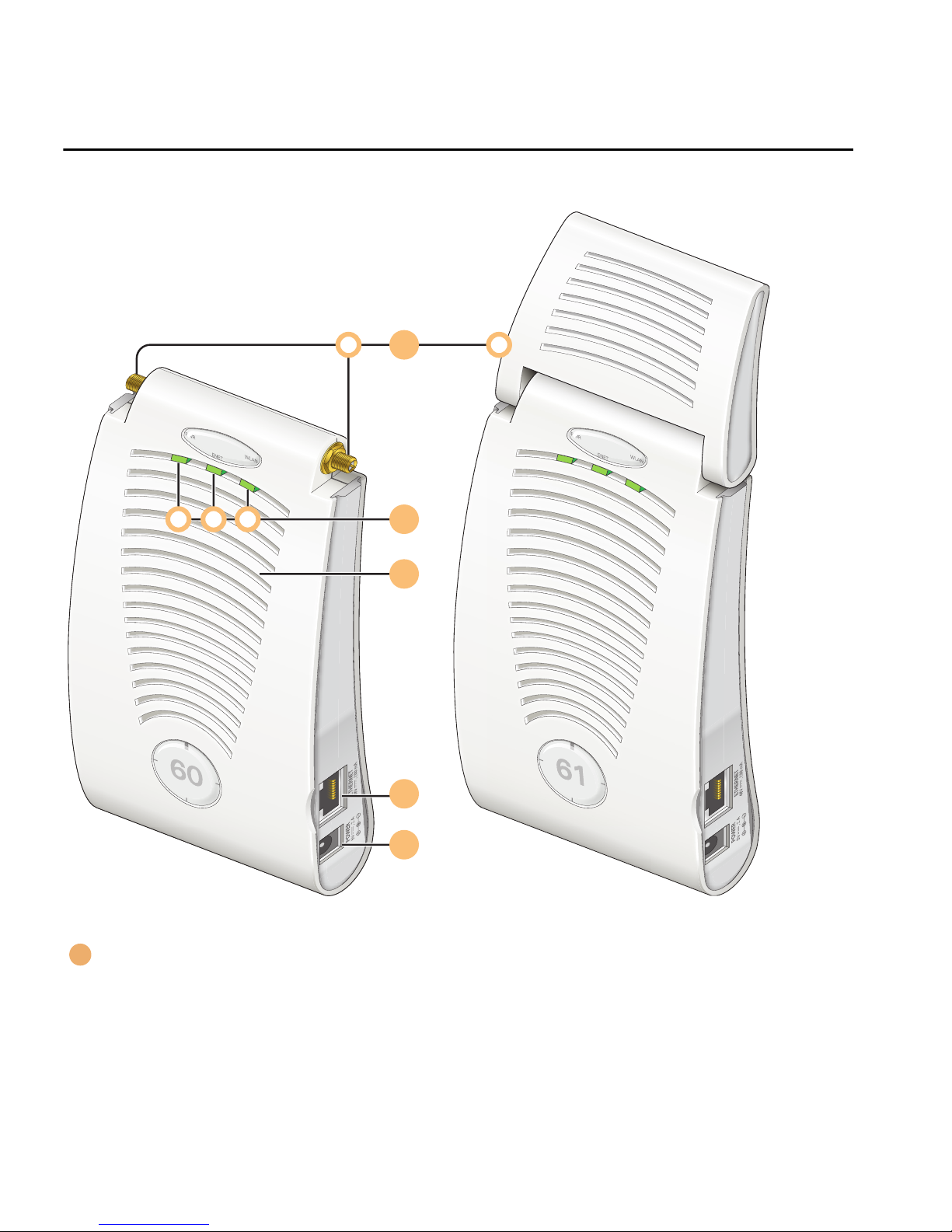
Front View . . . . . . . . . . . . . . . . . . . . . . . . . . . . . . . . . . . . . . . . . . . . . . . . . . 2
Back View . . . . . . . . . . . . . . . . . . . . . . . . . . . . . . . . . . . . . . . . . . . . . . . . . . 5
The Aruba AP Setup Process . . . . . . . . . . . . . . . . . . . . . . . . . . . . . . . . 6
Chapter 2 AP Deployment. . . . . . . . . . . . . . . . . . . . . . . . . . . . . . . . . . . . . . . . . . 7
Mounting the Aruba AP-60/61 . . . . . . . . . . . . . . . . . . . . . . . . . . . . . . . 7
Aruba AP-60 Detachable Antennas . . . . . . . . . . . . . . . . . . . . . . . . 8
Free-Standing Placement . . . . . . . . . . . . . . . . . . . . . . . . . . . . . . . . . 11
Using the Built-In Mounting Slots . . . . . . . . . . . . . . . . . . . . . . . . . 12
Using the Optional Mounting Kits . . . . . . . . . . . . . . . . . . . . . . . . . 13
Connecting Required Cables . . . . . . . . . . . . . . . . . . . . . . . . . . . . . . . . 14
Selecting an FE Cable . . . . . . . . . . . . . . . . . . . . . . . . . . . . . . . . . . . . 14
Connecting Cables & Power . . . . . . . . . . . . . . . . . . . . . . . . . . . . . . 15
Selecting an Antenna . . . . . . . . . . . . . . . . . . . . . . . . . . . . . . . . . . . . . . . 16
Maintenance . . . . . . . . . . . . . . . . . . . . . . . . . . . . . . . . . . . . . . . . . . . . . . . 16
Appendix A Port Specifications. . . . . . . . . . . . . . . . . . . . . . . . . . . . . . . . . . . . . 17
FE Port . . . . . . . . . . . . . . . . . . . . . . . . . . . . . . . . . . . . . . . . . . . . . . . . . . . . 17
Serial Breakout Adapter. . . . . . . . . . . . . . . . . . . . . . . . . . . . . . . . . . . . . 18
DB-9 Specification . . . . . . . . . . . . . . . . . . . . . . . . . . . . . . . . . . . . . . . 18
“To AP” Specifications . . . . . . . . . . . . . . . . . . . . . . . . . . . . . . . . . . . 19
“To Network” Specifications. . . . . . . . . . . . . . . . . . . . . . . . . . . . . . 19
Compliance . . . . . . . . . . . . . . . . . . . . . . . . . . . . . . . . . . . . . . . . . . . . . . . . 21
United States . . . . . . . . . . . . . . . . . . . . . . . . . . . . . . . . . . . . . . . . . . . . 21
Appendix B Product Specifications . . . . . . . . . . . . . . . . . . . . . . . . . . . . . . . . 21
Canada . . . . . . . . . . . . . . . . . . . . . . . . . . . . . . . . . . . . . . . . . . . . . . . . . . 22
Japan . . . . . . . . . . . . . . . . . . . . . . . . . . . . . . . . . . . . . . . . . . . . . . . . . . . 23
Europe . . . . . . . . . . . . . . . . . . . . . . . . . . . . . . . . . . . . . . . . . . . . . . . . . . 23
Certifications. . . . . . . . . . . . . . . . . . . . . . . . . . . . . . . . . . . . . . . . . . . . . . . 25
Product Label . . . . . . . . . . . . . . . . . . . . . . . . . . . . . . . . . . . . . . . . . . . . 26
Product Features . . . . . . . . . . . . . . . . . . . . . . . . . . . . . . . . . . . . . . . . . . . 26
Ethernet Compatibility. . . . . . . . . . . . . . . . . . . . . . . . . . . . . . . . . . . . 26
Radio Characteristics. . . . . . . . . . . . . . . . . . . . . . . . . . . . . . . . . . . . . 26
Power Over Ethernet . . . . . . . . . . . . . . . . . . . . . . . . . . . . . . . . . . . . . 27

Contents
Chapter
iv Aruba AP-60/61 0510160-03
Installation Guide April 2008
Physical Description . . . . . . . . . . . . . . . . . . . . . . . . . . . . . . . . . . . . . . . . 27
Package Contents . . . . . . . . . . . . . . . . . . . . . . . . . . . . . . . . . . . . . . . 27
Optional Items . . . . . . . . . . . . . . . . . . . . . . . . . . . . . . . . . . . . . . . . . . . 27
Aruba AP-60 Access Point . . . . . . . . . . . . . . . . . . . . . . . . . . . . . . . . . . 28
Aruba AP-61 Access Point . . . . . . . . . . . . . . . . . . . . . . . . . . . . . . . . . . 33
Related Documents. . . . . . . . . . . . . . . . . . . . . . . . . . . . . . . . . . . . . . . . . 37
Contacting Aruba Networks . . . . . . . . . . . . . . . . . . . . . . . . . . . . . . . . 38
Proper Disposal of Aruba Equipment . . . . . . . . . . . . . . . . . . . . . . . . 38
China RoHS . . . . . . . . . . . . . . . . . . . . . . . . . . . . . . . . . . . . . . . . . . . . . . . . 39

Aruba AP-60/61 1
Installation Guide
Introduction 1
The Aruba AP-60/61 is part of a comprehensive wireless network solution. The
device works in conjunction with the Aruba Mobility Controller and can act as a
wireless access point or air monitor.
As a wireless Access Point (AP), the Aruba AP-60/61 provides transparent,
secure, high-speed data communications between wireless network devices
(fixed, portable, or mobile computers with IEEE 802.11a or IEEE 802.11b/g
wireless adapters) and the wired LAN.
As a wireless Air Monitor (AM), a feature unique to Aruba products, the Aruba
AP-60/61 enhances wireless networks by collecting statistics, monitoring traffic,
detecting intrusions, enforcing security policies, balancing wireless traffic load,
self-healing coverage gaps, and more.
NOTE:Service to all Aruba Networks equipment must be performed by trained
service personnel only.

Introduction
Chapter 1
2Aruba AP-60/61 0510160-03
Installation Guide April 2008
Front View
FIGURE 1-1 Aruba AP-60/61 Front View
Antenna fixtures for Wireless Communications
Depending on the model, the AP will have one of the following:
1
2
3
4
5
A B
CBA
1

Aruba AP-60/61 3
Installation Guide
Introduction
Chapter 1
Aruba AP-60–Two Reverse Polarity SMA (RP-SMA) connectors for attaching
separate antennas (not included). For details, see “Aruba AP-60 Detachable
Antennas” on page 8. (The AP-60 requires that both connectors be used in
ArubaOS 2.2 releases or lower. Single antenna operation is supported with
ArubaOS 2.3 or higher.)
NOTE:When facing the AP-60 as shown in Figure 1-1, the antenna
connector on the left is for antenna 1, and the connector on the right
is for antenna 2 in a diversity configuration.
Aruba AP-61–Built-in swivel array with dual, tri-band, omnidirectional
antennas.
Indicator LEDs
During operation, the Aruba AP-60/61 LEDs provide the following information:
NOTE:LEDs on the Mobility Controller provide additional status and security
information about connected APs.See the ArubaOS User Guide for more
information.
Air Vents
These vents promote proper air circulation for cooling the device. Do not allow
these vents to be obstructed by mounting equipment, network cables, or any
other material.
TABLE 1-1 Aruba AP-60/61 LEDs
LED State Description
PWR Off The device is off - no power.
Green-Solid The device is powered and operating.
ENET Off No link on the FE port. No connection to the
network.
Green-Solid Ethernet link detected on the FE port.
Green-Flashing Transmitting or receiving data across the FE
port. Flashing rate is proportional to network
activity.
WLAN Off The wireless interface is disabled or down.
Green-Solid The wireless interface is enabled and
functioning as an Access Point.
Green-Flashing The wireless interface is enabled and
functioning as an Air Monitor.
A
B
2
A
B
C
3

Introduction
Chapter 1
4Aruba AP-60/61 0510160-03
Installation Guide April 2008
FE Port
This port attaches the Aruba AP-60/61 to a 10Base-T/100Base-TX (twisted-pair)
Ethernet LAN segment. This port also supports Serial and Power Over Ethernet
(SPOE).
See Appendix 4, “Product Specifications.” for port and cable specifications.
DC Power Socket
This socket is used to connect the optional AC power adapter (not included). If
POE is being used to supply power to the Aruba AP-60/61, the power adapter is
not necessary.
4
5

Aruba AP-60/61 5
Installation Guide
Introduction
Chapter 1
Back View
FIGURE 1-2 Aruba AP-60/61 Back View
Mounting Slots
The keyhole-shaped slots on the back of the chassis are used for mounting the
Aruba AP-60/61.
Air Vents
These vents promote proper air circulation for cooling the device. Do not allow
these vents to be obstructed by mounting equipment, network cables, or any
other material.
1
3
2
4
1
2

Introduction
Chapter 1
6Aruba AP-60/61 0510160-03
Installation Guide April 2008
Fold-Out Stand
This fold-out stand allows the Aruba AP-60/61 to be stood upright on a table or
shelf.
Kensington Security Slot
This slot is compatible with a Kensington MicroSaver Security Cable (not
included) which can be used to prevent the unauthorized removal of the Aruba
AP-60/61 from its installed location. To secure the Aruba AP-60/61, wrap a
security cable around an immovable object, insert the cable’s lock into the
Kensington Security Slot, and turn the key.
NOTE:The serial number and model number are on the bottom of the unit.
The Aruba AP Setup Process
Setting up an Aruba AP typically consists of four stages:
WLAN Planning—The administrator determines how many Aruba APs will be
needed for their wireless network strategy and where they will be deployed. This
can be easily accomplished using Aruba’s automated RF Plan site-survey
software (available separately).
AP Provisioning—Provisioning provides each Aruba AP with initial settings that
allow it to locate the host Aruba Mobility Controller. Depending on the network
topology and services, AP provisioning can be performed manually for each AP or
plug-and-play for batches of APs.
AP provisioning is discussed in Appendix 2, “Provisioning Access Points.”
AP Deployment—Once provisioned, the AP can be physically installed at its
intended place of operation.
AP deployment is covered in Chapter 2, “AP Deployment”.
AP Configuration—The administrator defines the operational behavior for each
Aruba AP, such as RF characteristics and security features.
For AP configuration information, refer to the ArubaOS User Guide.
3
4

Aruba AP-60/61 7
Installation Guide
AP Deployment 2
This chapter covers the following topics:
zPhysical mounting of the Aruba AP-60/61
zConnecting the required cables
Mounting the Aruba AP-60/61
When provisioning is complete, mount the Aruba AP-60/61 at its intended service
location.
The Aruba AP-60/61 Access Points with or without external antennas are
intended only for installation in Environment A as defined in IEEE 802.3.af. All
interconnected equipment must be contained within the same building, including
the interconnected equipment's associated LAN connections. (When using an
external antenna, 5.150 to 5.250 MHz are blocked.)
Select a location as close as possible to the center of the intended coverage area.
If necessary, use the Aruba RF Plan site survey tool to determine the optimum
locations for your access points and air monitors.
The service location should be free from obstructions or obvious sources of
interference. Normally, the higher you place an access point or air monitor, the
better its performance.
If external antennas are used, make sure that they and their associated wiring are
located entirely indoors. The Aruba AP-60/61 and any optional external antennas
are not suitable for outside use.

AP Deployment
Chapter 2
8Aruba AP-60/61 0510160-03
Installation Guide April 2008
The Aruba AP-60/61 can be mounted on a wall or suspended from above (not
shown) using one of the optional mounting kits (dimensions vary) in the
following ways:
FIGURE 2-1 Aruba AP-60/61 Mounting Options
NOTE:For dimensions, see Appendix 4, “Product Specifications”. Allow 5
cm (2") additional space on the right-hand side for cables.
Measurements for the Aruba AP-60 depend on attached antennas,
which vary.
Aruba AP-60 Detachable Antennas
Before deploying the Aruba AP-60, attach the appropriate antennas (not
included). The antenna connections should be tightened by hand to avoid
overtightening.
The Aruba AP-60 has dual Reverse Polarity SMA (RP-SMA) antenna connectors
that accept a variety of high-gain detachable antennas. See Ta b l e 2 - 1 for the list
of FCC approved antennas tested for use with the Aruba AP-60.
Make sure that all external antennas and their associated wiring are located
entirely indoors. The Aruba AP-60 Access Points and their optional external
antennas are not suitable for outside use.
1 2 3

Aruba AP-60/61 9
Installation Guide
AP Deployment
Chapter 2
FCC-Approved Detachable Antennas
Table 3-1 lists the antennas that are approved for use with the Aruba AP-60.
TABLE 2-1 FCC-Approved Detachable Antennas
Aruba Part # Description Gain
dbi Manufacturer Man. Part #
MULTI-BAND ANTENNA
AP-ANT-1 Tri-Band,
High-Gain,
Omni-Directional
Antenna (Indoor)
(Swivel Connector)
5 Nearson T614AH-2.4
5/5.X-S
2.4Ghz (802.11B/G)
AP-ANT-2 High-Gain,
Omni-Directional
Cylindrical (Indoor)
with RP-SMA
Connector
6 Centurion IG2450-RPS
MA
AP-ANT-3 High-Gain,
Bi-Directional
Patch Antenna
(Indoor) with
RP-SMA
Connector
5 Centurion IB2450-RPS
MA
AP-ANT-4 High-Gain,
Directional Patch
Antenna (Indoor)
with RP-SMA
Connector
9 Centurion ID240-RPSM
A/CAF94379
AP-ANT-5 Down-Tilt,
Omni-Directional
Patch Antenna
(Indoor) with
RP-SMA
Connector
3.5 Cushcraft SQ2403PG3
6RSM
AP-ANT-7 High-Gain
Directional Patch
Antenna (Indoor /
Outdoor) with
RP-SMA
Connector
11.5 HD Comms.
Corp
PCW24-080
12-AFL/HD1
9656

AP Deployment
Chapter 2
10 Aruba AP-60/61 0510160-03
Installation Guide April 2008
AP-ANT-8 High-Gain,
Omni-Directional
Cylindrical (Indoor /
Outdoor) with
RP-SMA
Connector
5 Cushcraft S2403BPX3
6RSM
5Ghz (802.11A)
AP-ANT-10 High-Gain,
Omni-Directional
Cylindrical (Indoor /
Outdoor) with
RP-SMA
Connector
5.5 Cushcraft S5153WBPX
36RSM
AP-ANT-11 Down-Tilt,
Omni-Directional
Patch Antenna
(Indoor) with
RP-SMA
Connector
3.5 Cushcraft SQ5153WP3
6RSM
AP-ANT-12 High-Gain,
Directional Patch
Antenna (Indoor /
Outdoor) with
RP-SMA
Connector
14 Cushcraft S52514WP3
6RSM
TABLE 2-1 FCC-Approved Detachable Antennas (Continued)

Aruba AP-60/61 11
Installation Guide
AP Deployment
Chapter 2
Free-Standing Placement
To place the Aruba AP-60/61 indoors on a flat table or shelf:
Flip open the stand located on the back of the Aruba AP-60/61:
FIGURE 2-2 Aruba AP-60/61Fold-Out Stand
Place the device on a sturdy table or shelf.
Orient the antennas.
For best performance, swivel the individual antennas (Aruba AP-60) or antenna
array (Aruba AP-61) so that they are oriented vertically. Once mounting is
complete, connect the required cables (see instructions on page 14).
CAUTION:Do not place the Aruba AP-60/61 in any place where it
could fall on people or equipment. For more secure
installation, use one of the optional mounting kits.

AP Deployment
Chapter 2
12 Aruba AP-60/61 0510160-03
Installation Guide April 2008
Using the Built-In Mounting Slots
The keyhole-shaped slots on the back of the Aruba AP-60/61 can be used to
attach the device upright to an indoor wall or shelf.
To hang the Aruba AP-60/61 upright using the mounting slots, perform the
following steps.
1. Install two screws in the wall or shelf as shown in Figure 2-3:
FIGURE 2-3 Mounting Screw Specifications
If attaching the device to drywall, we recommend using appropriate wall
anchors (not included) as shown in Figure 2-4 on page 13.
CAUTION:Do not use the mounting slots to hang the Aruba
AP-60/61 from the ceiling, sideways, or in any place
where it could fall on people or equipment. For more
secure installation, use one of the optional mounting kits.
Screw/Nail Positions
(fastened to wall or shelf)
12.7 cm
(5.00")
0.12"
0.27"
0.23"
0.05"
clearance
from surface
3.0 mm
5.8 mm
0.08"
0.15"
clearance
from surface
2.0 mm
3.8 mm
clearance
from surface
1.3 mm
clearnace
from surface
7.0 mm
Maximum Minimum
Screw/Nail Dimensions

Aruba AP-60/61 13
Installation Guide
AP Deployment
Chapter 2
2. Align the Aruba AP-60/61 mounting slots to capture the surface screws.
FIGURE 2-4 Hanging the Aruba AP-60/61 on Screws
3. Secure the Aruba AP-60/61, if desired.
To prevent the unauthorized removal of the Aruba AP-60/61 from its installed
location, use a Kensington MicroSaver Security Cable (not included). Wrap
the security cable around an immovable object, insert the cable’s lock into the
Kensington Security Slot on the back of the Aruba AP-60/61, and turn the
key.
4. Orient the antennas.
For best performance, swivel the individual antennas (Aruba AP-60) or antenna
array (Aruba AP-61) so that they are oriented vertically (see Figure 2-1 on page 8).
Once mounting is complete, connect the required cables (see instructions on
page 14).
Using the Optional Mounting Kits
Use the optional mounting kit to attach the Aruba AP-60/61 to a wall, shelf, or
ceiling. For installation, see the Aruba AP-60/61 Mounting Kit Installation Notes
(P/N 0500037-01) provided with each kit.

AP Deployment
Chapter 2
14 Aruba AP-60/61 0510160-03
Installation Guide April 2008
Connecting Required Cables
The Aruba AP-60/61 Access Points with or without external antennas are
intended only for installation in Environment A as defined in IEEE 802.3.af. All
interconnected equipment must be contained within the same building, including
the interconnected equipment's associated LAN connections.
Selecting an FE Cable
The 10/100 Mbps Ethernet (FE) port is used to connect the AP to a
10Base-T/100Base-TX (twisted-pair) Ethernet LAN segment. The appropriate FE
cable depends on the features required of the FE port:
zSPOE
When connecting the AP to a device that supports Serial and Power Over
Ethernet (SPOE), use an 8-conductor, Category 5 UTP, straight-through FE
cable.
The Aruba 5000 (with Line Card LC-5000-24FE-2GE-SPOE), the Aruba 2400,
and the Aruba 800 support SPOE.
zPOE
If the connecting device supports only Power Over Ethernet (POE), use a 4- or
8-conductor, Category 5 UTP, straight-through FE cable.
zNetwork Only
If the connecting device does not support POE, use a 4- or 8-conductor,
Category 5 UTP, FE cable. The port detects MDI/MDX and automatically
adjusts for straight-through or crossover cables.
The maximum length for FE cables is 100 meters (325 feet).
When the Aruba AP-60/61 is installed in an air-handling space, such as above
suspended ceilings, as described in National Electrical Code (2002) Article
300.22(C), and Canadian Electrical Code, Sections 2-128, 12-010(3) and 12-100,
Part 1, CSA C22.1, POE is required. Also, any FE cable installed in such spaces
should be suitable under NEC Article 800.50 and marked accordingly for use in
plenums and air-handling spaces with regard to smoke propagation, such as
CL2-P, CL3-P, MPP, or CMP.
Use the built-in antenna (for the AP-61). For the Aruba AP-60, use Aruba
AP-ANT-1. For all other antennas, make sure the antenna cable is UL listed and
suitable for use in plenums and air-handling spaces, such as CL2-P, CL3-P, MPP,
or CMP, and mount the antenna outside of the air-handling space.
Install cables in accordance with all applicable local and national regulations and
practices.
For more port and cable details, see Appendix 3, “Port Specifications.”

Aruba AP-60/61 15
Installation Guide
AP Deployment
Chapter 2
Connecting Cables & Power
1. Connect one end of the FE cable directly to the Aruba AP-60/61 FE port.
2. Connect the other end of the FE cable to one of the following:
To a network port on the Mobility Controller, or
To a network hub, router, or switch that has a routable path to the
Mobility Controller.
NOTE:If the connecting device supplies POE, a straight-through cable must
connect the Aruba AP-60/61 directly to the powering device without any
intervening hubs, routers, or other networking equipment.
3. Connect power, if necessary.
The Aruba AP-60/61 can receive electrical power using the following options:
zPOE
If connecting the Aruba AP-60/61 to a device that supplies IEEE 802.3af
compliant POE no additional power connection is necessary.
zPower Outlet
NOTE:When the Aruba AP-60/61 is installed in an air-handling space, as
described in NEC (2002) Article 300.22(C), POE must be used instead
of a power outlet.
If local regulations and practices permit, connect the optional AC power adapter
(not included) to the DC power socket on the Aruba AP-60/61 and plug it into an
appropriate power outlet.
CAUTION:To prevent personal injury or damage to equipment, be
sure to comply with electrical grounding standards during
all phases of installation and operation of the AP. Do not
allow the Aruba AP-60/61 or its attachments to be
connected to or make contact with metal or power outlets
on a different electrical ground than the device to which it
is connected. Also, never connect the AP or Mobility
Controller to external storm grounding sources.
CAUTION:To prevent personal injury or damage to equipment,
use only the AC power adapter certified for this device
in the country where it is used.
A
B

AP Deployment
Chapter 2
16 Aruba AP-60/61 0510160-03
Installation Guide April 2008
Selecting an Antenna
There are three ways to select an AP-60 antenna:
1. From the AP console (serial or telnet) enter set_antenna 0|1|2 where 0
specifies auto mode, and 1 or 2 chooses a specific antenna. The antenna
selection is not persistent and the AP will loose the antenna selection, if
rebooted.
2. From the AP boot prompt (apboot>) enter a_antenna 0|1|2 or g_antenna 0|1|2
to specify an antenna. Enter a save command before booting the AP to save
the antenna configuration in the AP’s Flash memory, along with other
provisioning parameters.
3. For releases 2.3 and higher, you can provision the antenna selection from the
Mobility Controller.
Maintenance
The AP-60 and AP-61 require no maintenance beyond keeping the AP clean and
dust free. To clean the Aruba AP-60/61, use a static-free, dry cloth.
Aruba recommends that these units be inspected annually for damage, dust
buildup, and to verify that all connections are secure.
Other manuals for AP-60
2
This manual suits for next models
1
Table of contents
Other Aruba Wireless Access Point manuals

Aruba
Aruba 503H User manual

Aruba
Aruba 340 Series User manual

Aruba
Aruba AP-103H User manual

Aruba
Aruba 570 Series User manual

Aruba
Aruba AP-515S User manual

Aruba
Aruba 610 Series User manual

Aruba
Aruba 300 series User manual

Aruba
Aruba AP-65-MNT Quick start guide

Aruba
Aruba A200 User manual

Aruba
Aruba 303P Series User manual

Aruba
Aruba AP 70 User manual

Aruba
Aruba RAP-5WN User manual

Aruba
Aruba AP-318 User manual

Aruba
Aruba Instant On AP12 User manual

Aruba
Aruba AP-270-MNT-V1 User manual

Aruba
Aruba AP-68 User manual

Aruba
Aruba 610 Series User manual

Aruba
Aruba 220 Series User manual

Aruba
Aruba 200 Series User manual

Aruba
Aruba AP17 User manual