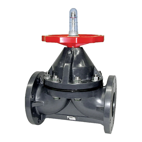
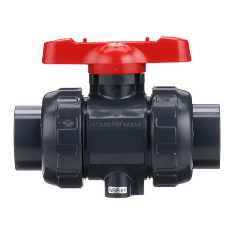
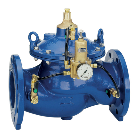
ASAHI Constant Flow Series User manual

ASAHI AV VALVES Installation,Operation and Maintenance Manual
Constant Flow Valves 0
Serial No. H – V019 E – 2
Constant Flow Valves
User’s Manual
Contents
(1) General operating instructions 1
(2) General care & storage instructions 2
(3) Names of parts 2
(4) Specifications 3
(5) Principle & Operation 4
(6) Installation procedure 5
(7) Operating procedure 6
(8) Inspection items 6
(9) Troubleshooting 6
(10) Disassembly procedure for cleaning
the inside of valve 7
(11) Handling of residual and waste materials 9
(12) Inquires 10
ASAHI AV VALVES

ASAHI AV VALVES Installation,Operation and Maintenance Manual
Constant Flow Valves 1
(1) General operating instructions
○Operate the valve within the pressure Vs temperature range.
(The valve can be damaged by operating beyond the allowable range.)
○ Select a valve material that is compatible with the media, refer to “CHEMICAL RESISTANCE ON
ASAHI AV VALVE”.
(Some chemicals may damage incompatible valve materials.)
○The valve is not designed to bear any kind of external load. Never stand on or place anything heavy on the
valve at anytime.
○When the valve is disposed of, contact waste disposal specialist.
(The valve generates toxic gas.)
○Do not store or install the valve near any heat source or hot surface.
(It may cause deformation, destruction, and fire.)
○The valve should be installed at place where space for periodic inspection & maintenance is sufficient.
○The flow rate scale of the opening indicator has already been adjusted before the products shipped so
that the differences between reading and actual values meet the standard accuracy within ±6% of full
scale.
○Regardless of horizontal installation or vertical installation, the strainer with the 60-mesh should be
installed in the upper stream line of the valve in order to avoid the malfunction possibility caused by
clogging of the foreign matters.
Do not set the configuration as shown in the drawing-1, because it may malfunction.
(Other than ultra pure water lines.)
○Every type of valve has its one flow direction across the valve.
Make sure, therefore, that the flow direction is consistent with the arrow-mark indicated on the valve
body when installed.
○Do not use the valve for the fluid having a viscosity
of more than 30cp.
○Regarding Specific Gravity, it should be less than 1.4
at the size of 15mm (1/2”) to 80mm (3”) and less
than 1.1 at 100mm (4”).
Drawing - 1
×
Caution

ASAHI AV VALVES Installation,Operation and Maintenance Manual
Constant Flow Valves 2
(2) General care & storage instructions
○Since The Asahi AV constant flow valve has four types of A-D according to piping and fluid conditions,
make sure of the product specifications after removing the valve from the packing case.
○Keep the valve in its original packaging until needed for installation.
○Avoid contact with any coal tar creosote, insecticides, vermicides or paint.
(The force of swelling may damage the valve.)
○The valve is not designed to handle any kind of impact. Avoid dropping the valve.
○Avoid scratching the valve with any sharp object.
(3) Names or parts
15mm (1/2”), 20mm (3/4”)
No. DESCRIPTION No. DESCRIPTION
◯
1BODY ◯
14 SLEEVE
◯
2BONNET ◯
15 CAP
◯
3CYLINDER ◯
16 KEY
◯
4PISTON ◯
17 CAP NUT
◯
5PLUG ◯
18 NUT
◯
6SPRING BASE ◯
19 THRUST RING
◯
7STOP RING ◯
20 SPRING (A)
◯
8ORIFICE ◯
21 SPRING (B)
◯
9SEAT ◯
23 WASHER (B)
◯
10 O-RING (A) ◯
24 HANDLE BASE
◯
11 O-RING (B) ◯
25 HANDLE COVER
◯
12 O-RING (C) ◯
26 SCREW
◯
13 O-RING (D)
25mm (1”), 50mm (2”) , 80mm (3”), 100mm (4”)
No. DESCRIPTION No. DESCRIPTION
◯
1BODY ◯
14 SLEEVE
◯
2BONNET ◯
15 CAP
◯
3CYLINDER ◯
16 KEY
◯
4PISTON ◯
19 THRUST RING
◯
5PLUG ◯
20 SPRING (A)
◯
6SPRING BASE ◯
21 SPRING (B)
◯
7STOP RING ◯
22 WASHER (A)
◯
8ORIFICE ◯
23 WASHER (B)
◯
9SEAT ◯
27 HAND WHEEL
◯
10 O-RING (A) ◯
28 MACHINE SCREW
◯
12 O-RING (C) ◯
29 LIFT INDICATOR
◯
13 O-RING (D)

ASAHI AV VALVES Installation,Operation and Maintenance Manual
Constant Flow Valves 3
(4) Specifications
●Working Temperature : PVC = 0-50℃(30 - 120°F), C-PVC = 0-70℃(30 – 160°F)
●Upstream Working Pressure : 0.25MPa (2.6kgf / cm2) or less
0.25 to 0.5 MPa (2.6 to 5.1kgf / cm2)
0.5 to 0.75 MPa (5.1 to 7.7kgf / cm2)
0.75 to 1.0 MPa (7.7 to 10.2kgf / cm2)
* Nom. size 100mm (4”) is 0.5 MPa (5.1kgf / cm2) or less only.
0.1MPa = 14.286PSI
● A Type [ 25mm (1”) – 80mm (3”) ]
Fluid flows through the valve inside Suitable for
semi-conductor industry.
(Ultra pure water line)
● B Type [ 15mm (1/2”) – 80mm (3”) ]
Flow rate setting range is large.
(Covers small flow rate to large rate)
● C Type [ 15mm (1/2”) – 100mm (4”) ]
Range of working differential pressure is large.
(For lines with large pressure differential between
upstream & downstream)
● D Type [ 80mm (3”) – 100mm (4”) ]
A large flow rate can be set.
Flow
Flow
Flow
Flow

ASAHI AV VALVES Installation,Operation and Maintenance Manual
Constant Flow Valves 4
(5) Principle & Operation
Refer to Figure 1 for design and operation of ASAHI AV
Flow Control Valve. When the upstream fluid pressure, P1
is introduced at the flow control orifice, it exerts a
corresponding pressure on the upper surface of the flange
on the piston type valve plug.
Likewise, the downstream pressure, P2exerts a
corresponding pressure to the lower surface of the valve
plug flange. Thus, when a differential pressure exists
between the fluid upstream and downstream of the orifice,
the corresponding pressure differential acting on the
surfaces of the flange moves the valve plug piston either
downward against the force of the spring cartridge or
upward by the force the spring, depending upon the
direction of the force induced by the existing pressure
differential.
This upward or downward movement of the valve plug
piston causes the flow orifice to be widened or narrowed
accordingly, thus the flow rate of the fluid passing across
the orifice is automatically adjusted.
For example, if the pressure differential, P1- P2 created between the upstream and downstream side of the
orifice increases, the valve plug piston moves downward to narrow the area of the orifice opening and
automatically adjusts the orifice to the preset flow rate value. (With the type of B, C and D, the plug has no
inlet hole for fluid, as the pressure differential P1- P2exerts directly on the surface of the plug.)
The reverse is also true when the pressure differential decreases, the piston moves upward increasing the
orifice opening area and allowing the fluid flow rate to increase to the preset value.
Preset flow rate range for use Design flow rate ranges:
Nom. size TYPE Flow rate (m3/hr) Rangeability Working differential pressure
TYPE B 0.04 - 0.8 20 : 1 0.02 - 0.1MPa (0.2 - 1.0kgf/㎝2)
15mm
(1/2”) TYPE C 0.08 - 0.8 10 : 1 0.03 - 0.2 MPa (0.3 - 2.0 kgf/㎝2)
TYPE B 0.06 - 1.2 20 : 1 0.02 - 0.1 MPa (0.2 - 1.0 kgf/㎝2)
20mm
(3/4”) TYPE C 0.12 - 1.2 10 : 1 0.03 - 0.2 MPa (0.3 - 2.0 kgf/㎝2)
TYPE A 0.5 - 2.0 4 : 1 0.02 - 0.1 MPa (0.2 - 1.0 kgf/㎝2)
TYPE B 0.1 - 2.0 20 : 1 0.02 - 0.1 MPa (0.2 - 1.0 kgf/㎝2)
25mm
(1”) TYPE C 0.2 - 2.0 10 : 1 0.03 - 0.2 MPa (0.3 - 2.0 kgf/㎝2)
TYPE A 2.0 - 8.0 4 : 1 0.02 - 0.1 MPa (0.2 - 1.0 kgf/㎝2)
TYPE B 0.4 - 8.0 20 : 1 0.02 - 0.1 MPa (0.2 - 1.0 kgf/㎝2)
50mm
(2”) TYPE C 0.8 - 8.0 10 : 1 0.03 - 0.2 MPa (0.3 - 2.0 kgf/㎝2)
TYPE A 5.0 - 20.0 4 : 1 0.02 - 0.1 MPa (0.2 - 1.0 kgf/㎝2)
TYPE B 1.0 - 20.0 20 : 1 0.02 - 0.1 MPa (0.2 - 1.0 kgf/㎝2)
TYPE C 2.0 - 20.0 10 : 1 0.03 - 0.2 MPa (0.3 - 2.0 kgf/㎝2)
80mm
(3”)
TYPE D 15.0 - 30.0 2 : 1 0.03 - 0.15 MPa (0.3 - 1.5 kgf/㎝2)
TYPE C 10.0 - 60.0 6 : 1 0.03 - 0.2 MPa (0.3 - 2.0 kgf/㎝2)
100mm
(4”) TYPE D 30.0 - 60.0 2 : 1 0.02 - 0.2 MPa (0.2 - 2.0 kgf/㎝2)
1m3/hr = 4.4033gal/min, 0.1MPa = 14.286PSI
Fig. 1

ASAHI AV VALVES Installation,Operation and Maintenance Manual
Constant Flow Valves 5
(6) Installation procedure
●Spanner wrench ●Torque wrench
●Bolt, Nut, Washer (Vary per flange type)
●AV Gasket ( Tightening torque will change if AV Gasket is not used. )
Procedure
1) Set the AV Gasket between the flanges.
2) Insert washers and bolts from the pipe side, insert washers and nuts from the valve side, then
temporarily tighten them by hand.
Unit : mm (inch)
Nom. Size Axial
Misalignment
Parallelism
(a-b)
15-25mm
(1/2”-1”) 1.0 (0.04) 0.5 (0.02)
40-80mm
(1 1/2”-3”) 1.0 (0.04) 0.8 (0.03)
100mm
(4”) 1.0 (0.04) 1.0 (0.04)
3) Using a torque wrench, tighten the bolts and nuts gradually to the specified torque in a diagonal manner
(Refer to fig.1.)
Recommenden torque value Unit:N-m{kgf-cm}[lb-inch]
Nom. Size 15mm
(1/2”)
20mm
(3/4”)
25mm
(1”)
50mm
(2”)
80mm
(3”)
100mm
(4”)
Torque value
17.5
(179)
[155]
17.5
(178)
[155]
20.0
(204)
[177]
22.5
(230)
[200]
30.0
(306)
[266]
30.0
(306)
[266]
Necessary items
(Axial misalignment) (Parallelism)
Avoid excessive tightening. (The valve can be damaged.)
Fig. 1
Caution
The parallelism and axial misalignment of the flange surface should be under the values shown
in the following table to prevent damage the valve.
(A failure to observe them can cause destruction due to stress application to the pipe)
Caution

ASAHI AV VALVES Installation,Operation and Maintenance Manual
Constant Flow Valves 6
(7) Operating procedure
○To operate the valve for opening / closing, turn the hand wheel slowly.
( To get the flow rate decreased, turn the hand wheel clockwise.)
To set new flow rate, turn the hand wheel counterclockwise to let the indicator of opening
degree reach beyond the required level and then the hand wheel clockwise to obtain proper
flow rate .
( This is the recommendable procedure to get exact flow rate.)
○To shut the valve, turn the hand wheel clockwise, and adjust the indicator to the “ 0 ” position of the
flow rate scale.
Application of rubber material for shut – off seat gives the valve perfect closing with little tightening
torque.
Do not operate the valve out of scale, especially at lower level than the minimum indicated scale.
(The function of valve could be deteriorated.)
(8) Inspection items
○Inspect the following items
(1) Existence of scratches, cracks, deformation, and discoloring.
(2) Existence of leakage from the valve to the outside.
(3) Existence of leakage when the valve is opened fully at right or left.
(9) Troubleshooting
Problem Cause Treatment
Insufficient Working differential
pressure. Adjust Working differential pressure.
Foreign materials are caught. Clean.
Appearance of algae or seaweed on
the surface of valve inside. Clean.
The flow rate is
extraordinarily small
Sand is caught in the valve. Clean.
The plug is damaged or worn. For further detail and assistance, consult
your nearest AOC agents / branches.
The orifice is damaged or worn. For further detail and assistance, consult
your nearest AOC agents / branches.
It has exceeded beyond the range of
Working differential pressure. Adjust Working differential pressure.
Appearance of algae or seaweed on
the surface of valve inside. Clean.
The flow rate is larger
than the range of
recommended flow rate.
Sand is caught in the valve. Clean.
Appearance of algae or seaweed on
the surface of valve inside Clean.
Fluid is not stopped in
the full shut position. Sand is caught in the valve. Clean.
Caution
Caution

ASAHI AV VALVES Installation,Operation and Maintenance Manual
Constant Flow Valves 7
(10) Disassembly procedure for cleaning the inside of valve
●Strap Wrench (*Removal of the bonnet) ●Snap Ring Plier (*Removal of the bonnet)
●Nylon Brush (*Wash The Parts) ●Grease “Silicon Grease”
○Do not disassemble valve under pressure.
○Do not disassemble the parts not mentioned above.
○Avoid scratching the inside parts with any sharp objects.
○Avoid scratching surface of the valve with any sharp objects.
○Follow the procedure in setting the flow rate.
Dissassembly
1) Open the valve fully.
2) Check for marking between the body and bonnet. If there is no marking, please make alignment
marks with a marker as follows.
*Note ; No need for marking on 15mm(1/2”) and 20mm(3/4”) in nominal size.
3) Loosen the bonnet with a strap wrench, and remove it.
4) Remove the snap ring with a snap ring plier.
Necessary items
Caution
Marking
Marking
(Using a marker)
Snap ring

ASAHI AV VALVES Installation,Operation and Maintenance Manual
Constant Flow Valves 8
5) Remove the piston from the cylinder.
Washing
1) Check the valve parts for damages.
2) Wash the valve parts with a nylon brush.
Assembly
1) Insert the piston into the cylinder smoothly, then insert the snap ring tightly.
2) If there is no grease around the o-ring of the cylinder, apply a sufficient amount of grease to the
surface of the o-ring.

ASAHI AV VALVES Installation,Operation and Maintenance Manual
Constant Flow Valves 9
3) Check whether the piston moves smoothly. If not, wash the valve again.
4) Cycle the piston assembly to 1/2 open position to keep alignment pins from falling into the bonnet
cavity.
*Note ; The valve 15mm(1/2”) and 20mm(3/4”) in nominal size have alignment pins.
5) Insert the bonnet into the body.
*Note ; The valve 15mm(1/2”) and 20mm(3/4”) in nominal size have alignment pins that fit
internal grooves to set normal position.
6) Tighten the body by hand, and using a strap wrench, tighten the bonnet until alignment
marks line up.
*Note-1 ; The valve 15mm(1/2”) and 20mm(3/4”) in nominal size don’t have alignment marks.
*Note-2 ; Avoid excessive tightening.(The valve can be damaged.)
Run fluid
1) Set the flow indicator to the preset flow rate.
2) Run fluid. (Operate the hand wheel slowly.)
(11) Handling of residual and waste materials
In discarding remaining or waste materials, be sure to ask waste service company.
(Poisonous gas is generated.)
Caution

ASAHI AV VALVES Installation,Operation and Maintenance Manual
Constant Flow Valves 10
(12) Inquires
ASAHI ORGANIC CHEMICALS INDUSTRY CO., LTD.
Nobeoka Head Office : 2-5955, Nakanose- Cho, Nobeoka –City, Miyazaki- Pref. , Japan.
Tel : (81) 982-35-0880 Fax : (81) 982-35-9350
Tokyo Head Office : (Furukawachiyoda Bldg.) 15-9, Uchikanda 2- Chome, Chiyoda-Ku, Tokyo,
Japan.
Tel : (81) 3-3254-8177 Fax : (81) 3-3254-3474
Singapore Branch Office : 16 Raffles Quay, #40-03 Hong Leong Building, Singapore 048581.
Tel : (65) 220-4022 Fax : (65) 324-6151
Europe Representative Office : Kaiser-Friedrich-Promenade 61 D-61348 Bad Homburg v. d. H. Germany.
Tel : (49) 6172-9175-0 Fax : (49) 6172-9175-25
Shanghai Branch Office : Room 1301-P Shanghai Kerry Center, 1515 Nanjing Xi Road, Shanghai China
Tel : (21) 5298-6900 Fax : (21) 5298-6556
ASAHI /AMERICA Inc. :35 Green Street P.O.Box 653 , Malden, Massachusetts 02148 U.S.A.
Tel : (1) 781-321-5409 Fax : (1) 781-321-4421
Distributor

ASAHI AV VALVES Installation,Operation and Maintenance Manual
Constant Flow Valves 11
Constant flow valve
2003. 12
ASAHI AV VALVES
Information in this manual is subject to change without notice.
Table of contents
Other ASAHI Control Unit manuals
