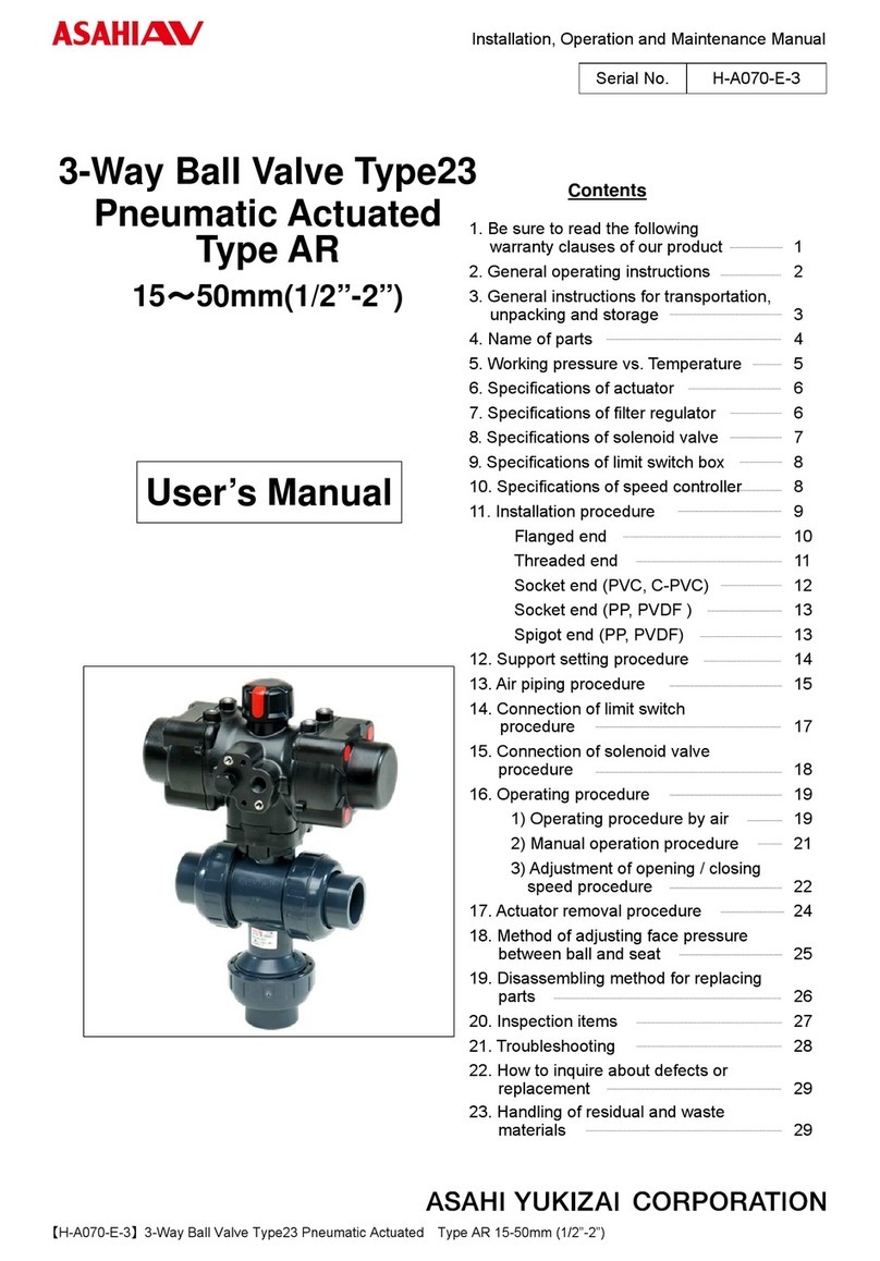
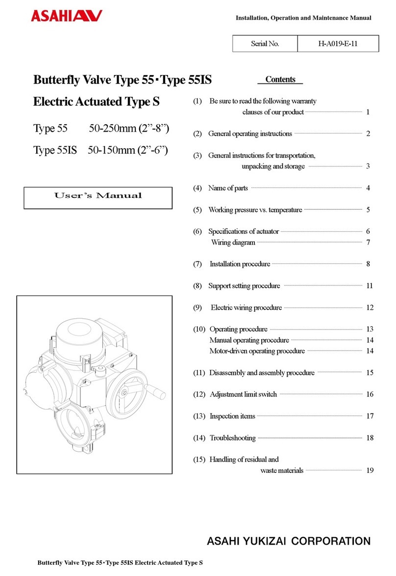
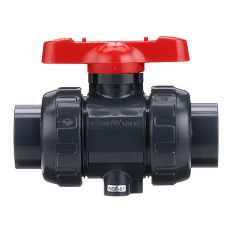
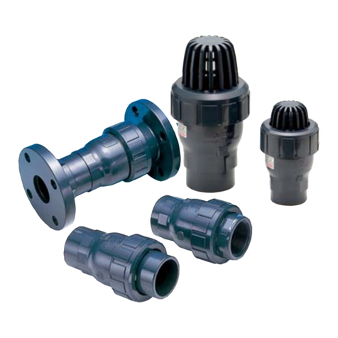
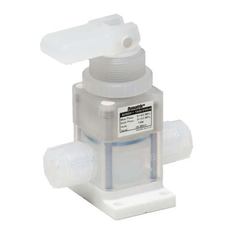
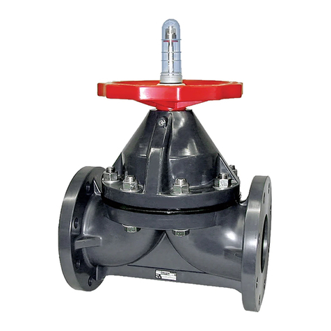
ASAHI 75 User manual

ASAHIAVVALVES Installation,OperationandMaintenanceManual
Butterfly Valves Type 75 0
Serial No. H – V 006E – 2
Contents
(1) General operating instructions
(2) General instructions for transportation,
unpacking and storage
(3) Name of parts
(4) Comparison between working
temperature and pressure
(5) Installation procedure
(6) Operating procedure
(7) Disassembly and assembly procedure for
parts replacement
(8) Adjustment procedure for stopper
(9) Inspection items
(10) Troubleshooting
(11) Handling of residual and
wastematerials
(12) Inquiries
8
8
4
3
2
1
1
Butterfly Valves Type 75
User’s Manual
8
9
6
6
7
ASAHI AV VALVES

ASAHIAVVALVES Installation,OperationandMaintenanceManual
Butterfly Valves Type 75 1
(1) General operating instructions
○Operate the valve within the pressure Vs temperature range.
(The valve can be damaged by operating beyond the allowable range.)
○Select a valve material that is compatible with the media, refer to “CHEMICAL RESISTANCE ON ASAHI AV
VALVE”.
(Some chemicals may damage incompatible valve materials.)
○Do not use the valve to fluid containing slurry. (The valve will not operate properly.)
○Do not use the valve on condition that fluid has crystallized.
(The valve will not operate properly.)
○Do not step on the valve or apply excessiveweight on valve. (It can be damaged.)
○Do not exert excessive force in closing the valves.
○Make sure to consult a waste treatment dealer to dispose of the valves.
(Poisonous gas is generated whenthe valve is burned improperly.)
○Allow sufficient space for maintenance and inspection.
○Keep the valve away from places ofdirect sunlight, water and dust. Use cover to shield the valve.
(The valve will not operate properly.)
○Set valve support on thevalve.
○Keep the valve away from excessive heator fire. (It can be deformed or destroyed.)
○In case of changing an operating part or replacing parts, drain the fluid completely from the pipe line.
(The stem will be pushed out by fluid pressureor the fluid leakage may occur.)
(2) General instructions for transportation, unpacking and storage
○Keep the valve packed in the cartonor box as delivered until installation.
○Keep the valve away from any coal tar, creosote (antiseptic for wood), termite insecticide, vermicides, and paint.
(This could cause swelling and damage the valve.)
○Do not impact or drop the valve. (It can bedamaged.)
○Avoid scratching the valve with any sharp object.

ASAHIAVVALVES Installation,OperationandMaintenanceManual
Butterfly Valves Type 75 2
(3) Name of parts
No. DESCRIPTION No. DESCRIPTION
◯
1Body ◯
7Stem
◯
1a Ring ◯
7a Key (A)
◯
2Disc ◯
25 Gear Box
◯
3Seat ◯
28 Bolt (C)
◯
4O-ring (A) ◯
29 Bolt (D)
◯
5O-ring (B) ◯
30 Stand
◯
6O-ring (C)
Gear type 450mm-600mm (18”-24”)

ASAHIAVVALVES Installation,OperationandMaintenanceManual
Butterfly Valves Type 75 3
Nominal size 450mm [18”]
Nominal size 500, 600mm[20”, 24”]
(4) Comparison between operating temperature and pressure
Do not operate the valve beyond the range of working temperature and pressure.
(The valve can be damaged.)
Caution

ASAHIAVVALVES Installation,OperationandMaintenanceManual
Butterfly Valves Type 75 4
In case of the thickness of the connection part (flange and pipe) is too thick, shave the flange or the pipe inside in order to avoid the
contactofpipe anddisc.Ifinside diameterofthe connectionpartislargerthansizeD,shavingis notnecessity.
Nominal size Diameter D
450mm (18”) 424mm (16.7”)
500mm (20”) 473mm (18.6”)
600mm (24”) 575mm (22.6”)
(5) Installation procedure
Fig.1 Fig.2
1) The valve disc is sent in the position indicated by solid lines in Fig.1 prior to shipment from the
factory. If the valve is opened or closed after unpacking, it must be reset in this position before
installation. Failure to do so will result in damage to the surface of the valve seat during handling and
installation.
2) The valve must not be dropped or thrown against other objects, since the sealing surface of the disc
and the sealing surface of the valve seat may easily be damaged.
3) Care must be used during piping installation to ensure that the pipes or flanges are properly aligned so
that the valve disc doses not contact them in any setting. Misalignment as in Fig.2 will result in
damage to the valve.
4) The installed valve must never be opened or closed when foreign matter such as sand is present in the
pipeline.
Caution

ASAHIAVVALVES Installation,OperationandMaintenanceManual
Butterfly Valves Type 75 5
●Torque wrench ●Spanner wrench ●Bolt-Nut-Washer (For many flanges specification.)
Procedure
1) Leave the disc ◯
2slightly opened by the handle.
2) Set the valve to the coupled flange.
3) Insert the connecting bolt-washer-nuts, and temporarily tighten
them by hand.
The parallelism and axial misalignment of the flange surface should be under the values shown in the following table to
prevent damage the valve.
(A failure to observe them can cause destruction due to stress application to the pipe)
Unit : mm [inch]
Nom. Size Axial
Misalignment Parallelism
(a-b)
450-600mm
[18”-24”] 1.5
[0.06] 1.0
[0.04]
4) Using a torque wrench, tighten the bolts and nutsgradually to the specified torque in a diagonal manner.
(Refer to fig. 1.)
Specified torque value Unit:N-m {kgf-cm} [lb-inch]
Nom. Size 450mm [18”] 500, 600mm [20”, 24”]
Torque value 80 {816} [710] 100 {1020} [887]
Bolt A Bolt B
Nom. Size dLS
d1LS1S2
Nut Washer
450mm
(18”) More than 315
More than [12.4] 120[4.8]
125[4.9]
500mm
(20”)
M24 More than 330
More than [13.0]
45
[1.8] M24 125[4.9]
135[5.3]
45
[1.8] 27
[1.1] M24 24
[0.94]
600mm
(24”) M30 More than 375
More than [14.8] 50
[20] M30 145[5.7]
155[6.1] 50
[20] 33
[1.3] M30 30
[1.2]
(Axialmisalignment) (Parallelism)
Avoid excessive tightening. (The valve can be damaged.)
Necessary items
Bolt A Bolt B
Gasket is not necessary. (The seat of the valve ◯
3can be replaced.)
Do not make the disc protrude from the seat.
(The disc may be damaged.)
Fig. 1
Caution
Caution
Caution
Caution
Unit :mm [inch]

ASAHIAVVALVES Installation,OperationandMaintenanceManual
Butterfly Valves Type 75 6
(6) Operating Procedure
○The indicator shows the position of the disc onthe top of gear box.
・For the full-shut position, the indication shows Shut [S].
・For the full-opened position, the indicationshows Open [O].
Full shut position Full opened position
(7) Disassembly and assembly procedure for pats replacement
Wear protective gloves and goggles for the case some dangerous fluid remains in the valve body.
(You might be injured.)
If gearbox need to be changed, there can not be line pressure present.
<< Disassembly >>
Procedure
1) Drain fluid completely from the pipeline and leave the valve slightly
opened.
2) Loosen the connecting bolts and nuts with a spanner wrench.
3) Remove the valve fromthe pipeline.
4) To take off the gearbox ◯
25 , loosen the bolt (C) ◯
28 and pull up the
gearbox.
5) Attach jack, thrust bearing, plate, and pipe to the valve, and thread the
jack into the stem ◯
7.
6) Remove the stem ◯
7from the jack.
Necessary items
●Protective gloves ●Safety goggles ●Spanner wrench
●Plate ●Thrust bearing ●Silicone grease
●Screwdriver(-) ●Jack
Caution

ASAHIAVVALVES Installation,OperationandMaintenanceManual
Butterfly Valves Type 75 7
7) Remove the O-ring (C) ◯
6.
8) Make the disc ◯
2fully open.
9) Pull out the both edges of seat ◯
7and remove the seat ◯
3and disc ◯
2.
10) Take the disc ◯
2out of the seat ◯
3.
11) Remove the O-ring (A) ◯
4and the O-ring (B) ◯
5.
<< Assembly >>
Procedure
1) Before starting assembly, silicone grease (equivalent to Toray Silicone
HVG) should be spread on the disc O-rings (A) ◯
4, (B) ◯
5and stem O-
ring (C) ◯
6.
2) The procedure of the assembly is the almost reverse of its disassembly.
However, to insert seat ◯
3with the disc ◯
2into the body ◯
1, set the disc
◯
2with half - opened position.
Press outer rim of seat ◯
3into inside of the body ◯
1, keeping stem holes
straight.
(Make sure that stem holes of the seat ◯
3are in alignment with the stem
holes of the body ◯
1.)
3) After assembly, make sure that the disc ◯
2fits seat ◯
3well.
(8) Adjustment procedure for stopper
●Protective gloves ●Allen wrench ●Spanner wrench
1) Remove the nut of Full-shut (Full-opening) adjuster.
2) Turn the stopper hex-bolt to required position by allen wrench.
3) Put the nut of Full-shut (Full-opening) adjuster back on gearbox.
N
ecessar
y
items
The ad
j
ustments for full-o
p
ened and full-shut
p
osition are ste
p
-less
,
and it can be done with the sto
pp
er ad
j
uster.
Caution

ASAHIAVVALVES Installation,OperationandMaintenanceManual
Butterfly Valves Type 75 8
(9) Inspection items
(1) Check for flaw, crack, or deformation on the valve.
(2) Check for leaks to the outside.
(3) Check for the deformation of seat due to improperinstallation of valve.
(4) Check for the smoothness of handle operation.
(10) Troubleshooting and action
Phenomenon Cause Treatment
Fluid is not stopped in
the full closed position
at the seat.
1) The stopper is not set correctly.
2) The seat is damaged or worn.
3) Foreign materials are caught.
4) The disc is damaged or worn.
5) The connecting bolts are over tightened
or tightened unevenly.
Adjust the stopper.
Replace the seat.
Clean up.
Replace the disc.
Adjust and retighten.
Fluid leaks to the
outside. 1) The seat is damaged or worn. Replace the seat.
The handle does not
work smoothly
1) Foreign materials have adhered.
2) The gearbox is damaged.
3) The connecting bolt is over tightened.
Adjust and retighten.
Replace the gearbox.
Adjust and retighten.
Valve doe not operated 1) The gearbox is damaged
2) The stem is damaged.
Repair or replace.
Replace the stem.
(11) Handling of residual and waste materials
In discarding remaining or waste materials, be sure to ask waste service company.
Caution

ASAHIAVVALVES Installation,OperationandMaintenanceManual
Butterfly Valves Type 75 9
(12) Inquiries
ASAHI ORGANIC CHEMICALS INDUSTRY CO., LTD.
Nobeoka Head Office : 2-5955, Nakanose- Cho, Nobeoka –City, Miyazaki- Pref. , Japan.
Tel : (81) 982-35-0880 Fax : (81) 982-35-9350
Tokyo Head Office : (Furukawachiyoda Bldg.)15-9, Uchikanda 2- Chome, Chiyoda-Ku, Tokyo, Japan.
Tel : (81) 3-3254-8177 Fax : (81) 3-3254-3474
Singapore Branch Office : 16 Raffles Quay, #40-03 Hong Leong Building, Singapore 048581.
Tel : (65) 220-4022 Fax : (65) 324-6151
Europe Representative Office : Kaiser-Friedrich-Promenade 61 D-61348 Bad Homburg v. d. H. Germany.
Tel : (49) 6172-9175-0 Fax : (49) 6172-9175-25
Shanghai Branch Office : Room 1301-P Shanghai Kerry Center, 1515 Nanjing Xi Road, Shanghai China
Tel : (21) 5298-6900 Fax : (21) 5298-6556
ASAHI /AMERICA Inc. :35 Green StreetP.O.Box 653 , Malden, Massachusetts 02148 U.S.A.
Tel : (1) 781-321-5409 Fax : (1) 781-321-4421
Distributor

ASAHIAVVALVES Installation,OperationandMaintenanceManual
Butterfly Valves Type 75 10
Butterfly Valves Type 75
Information in thismanual is subject to change without notice.
ASAHI AV VALVES
2003. 5
Table of contents
Other ASAHI Control Unit manuals
