Ascendor PLG7 User manual

Platform stair lift PLG7
ORIGINAL-user manual
Part 2: Assembly Instruction
English Version 2.00
ASCENDOR GMBH
Drautendorf 48
4174 Niederwaldkirchen
Austria
Tel.: +43 7231 40040
Fax: +43 7231 40040-590
www.ascendor.com

Page 2 Version 2.00 Assembly Instruction PLG7
Assembly Instruction
Platform stair lift PLG7
Date of issue: January 2015
Version 2.00
Part 2 / 3 of the original user manual
My ASCENDOR-partner is:

Assembly Instruction PLG7 Version 2.00 Page 3
Content
1. Introduction.....................................................................................................................................................4
1.1 Health and safety regulations..................................................................................................................4
1.2 Notes for installation...............................................................................................................................4
1.3Specific demands on the installation fitters ............................................................................................4
1.4 Additional information for the fitters......................................................................................................5
1.5 Personal safety equipment......................................................................................................................5
2. Schedule of installation ...................................................................................................................................5
3. Tools required for installation .........................................................................................................................6
4. Preparation before commencing installation..................................................................................................6
5. Setting up (assembly and adjustment) of the travel rails ...............................................................................7
6. Attaching the travel rails directly to the wall ..................................................................................................8
6.1 Choosing the correct fixing material .......................................................................................................8
6.2 Measurement of the first mounting hole................................................................................................8
6.3 Securing the travel rail mounting brackets ...........................................................................................10
7. Attaching the travel rails with stanchions / posts .........................................................................................11
7.1 Measurements of the first stanchion / post..........................................................................................11
7.2 Fixation of further stanchions / posts ...................................................................................................11
7.3 Fixation of rail cover panels...................................................................................................................12
8. Mounting the platform stair lift onto the travel rails....................................................................................13
9. Installing the battery charger ........................................................................................................................13
10. Fitting the limit switches ...........................................................................................................................14
11.Completing the installation .......................................................................................................................15
12. Sample installation drawing ......................................................................................................................16
13. Test report after finished installation........................................................................................................17
The further parts of the original user manual are:
•Part 1: Operating Manual
•Part 3: Maintenance and Service Manual

Page 4 Version 2.00 Assembly Instruction PLG7
1. Introduction
This assembly instruction is designed to assist you during the installation of the platform stair lift PLG7.
Although the information and photographs printed in this manual illustrate a particular stair lift, the
description is still relevant for all other installations.
Please note that this manual contains instructions for the installation of parts and equipment which are not
supplied with all our lifts (optional extras).
The instructions in this assembly manual describe equipment and tools which were available at the time of
writing. Due to the continuous development of our products, we reserve the right to alter the contents and
technical data without consultation or prior warning.
This part of the user manual is dedicated to trained installation technicians who are used to the installation of
this product.
1.1 Health and safety regulations
! N O T E !
In the interest of your own well being and the safety of third parties, please observe international health and
safety regulations and the applicable national laws at all time.
! A T T E N T I O N !
This lift is manufactured in compliance with the relevant international and national health and safety
directives. However that alone cannot guarantee safety and security. Incorrect operation or misuse of this
product can eventually cause heavy injuries of the user or third parties and result in damage to the lift and its
surroundings.
1.2 Notes for installation
•The installation of the platform stair lift may only be carried out by the trained personal of an
Ascendor partner.
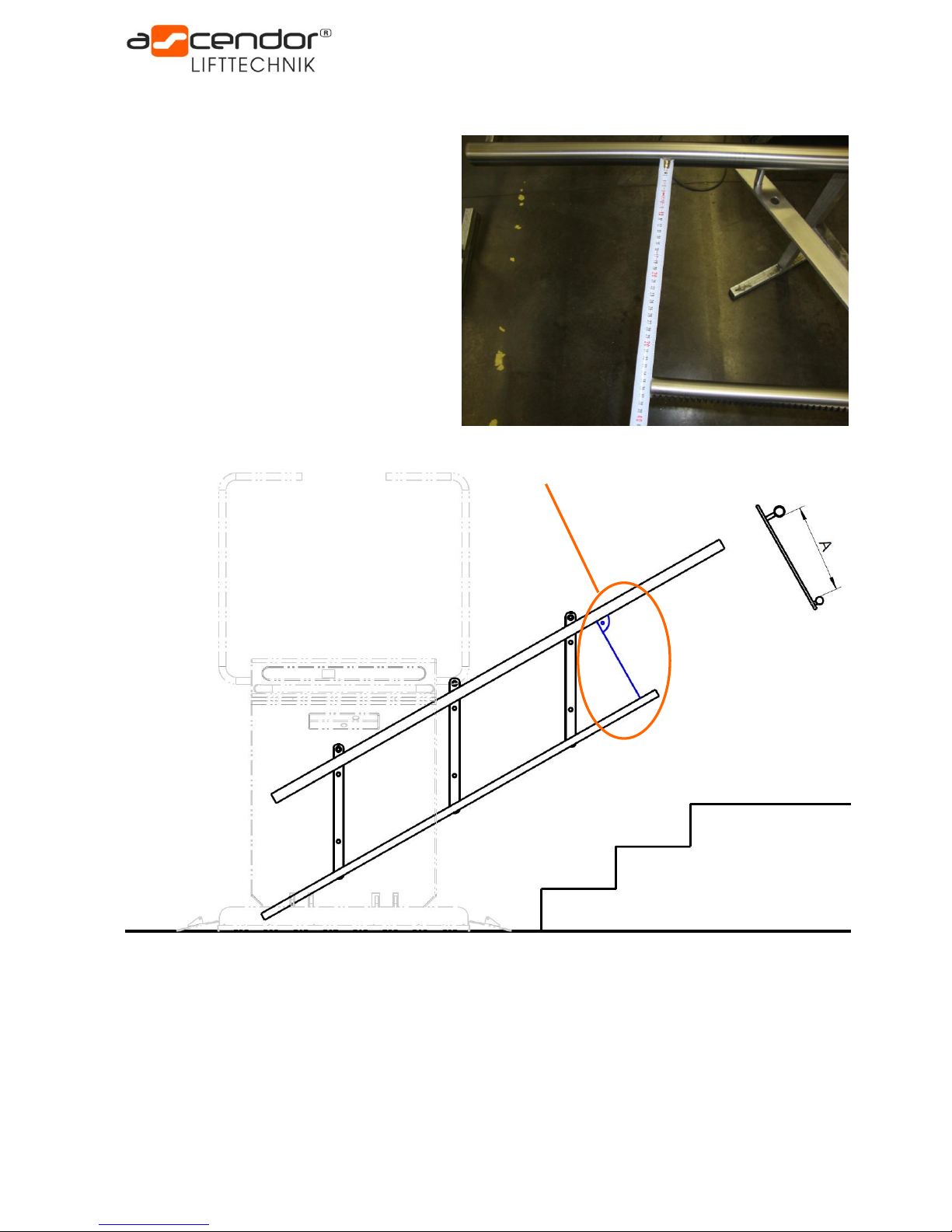
•This manual is designed to assist you with the installation and especially during the installation of the
travel rails of the stair lift.
•The travel rails of the stair lift may not be altered (extended or shorted).
•The stability of the walls, onto which the stair lift is to be mounted, must be assessed on site by a
qualified fitter. Ascendor accepts no responsibility and liability for this work.
•The exact installation dimensions are clearly specified in the drawing delivered with each stair lift and
must be observed at all times.
•A 230 V power socket or supply cable L/N/PE 3x1,5mm² must be either present or fitted at one of the
two lift stations (upper or lower station) during the installation.
1.3 Specific demands on the installation fitters
The installation fitters must be employed and trained by an Ascendor approved partner.
The fitters must be able to assess on site the load bearing capabilities of the walls and supporting elements to
which the lift and its equipment will be attached. They must be capable of reading and understanding the
provided installation drawings.
Ascendor accepts no responsibility or liability for this work.

Assembly Instruction PLG7 Version 2.00 Page 5
1.4 Additional information for the fitters
The weight of the lift varies between 125 and 140 kg, depending on the size of the platform and the number of
rechargeable cells supplied. A wheeled trolley or some form of carrying straps to assist in the transport of the
lift unit should be made available whenever possible.
The travel rail of the stair lift consists of one or more parts which can vary between 1 and 5 meters in length.
In case of uncertainty or arising questions, please refer to your Ascendor partner or do not hesitate to call our
customer service at +43 (0)7231/40040.
1.5 Personal safety equipment
During installation it is required to wear personal safety equipment to reduce the risk of injuries.
This equipment must be worn at all times during installation.
•General:
•additionally required for use of angular grinders or power drill:
2. Schedule of installation
•Check if the contents are complete and that no transport damages incurred during delivery
•Check if the actual dimensions of the staircase correspond with those mentioned in the installation
drawing. If you find major differences please contact Ascendor.
•Assembly and adjusting the travel rails
•Fixing the upper attachment bracket
•Position and align the travel rails
•Fasten the travel rails
•Mounting the platform stair lift onto the travel rails
•Fitting the limit switches
•Installing the battery charger
•Completing the installation
•Function test of the complete lift unit

Page 6 Version 2.00 Assembly Instruction PLG7
3. Tools required for installation
Ascendor recommends carrying following installation tools with you:
•Additional light sources for installation work
•Tape measure
•Spirit level, short, with digital display
•Spirit level, long approx. 1500mm
•One-hand bar clamp
•Cordless screwdriver incl. extender and drill bits
•Hand tools:
osocket wrench set with extensions and various inserts
oMulti-purpose pliers
oWire cutter
oWire stripper
oCrimping tool
oScrew driver
oScrew wrench
•Power drill incl. concrete drills
•Drills and tapping drills for threads
•Angular grinder
•Vacuum cleaner
•Draw wire or tape (for fitting electrical cable)
4. Preparation before commencing installation
Check the lift unit packaging (wooden crate), the packaging of the travel rails and if applicable, the packaging
of support brackets for any signs of damage.
If any signs of damage are visible, take some photos immediately and please register them with the haulage
company responsible and with Ascendor without delay.
Open the wooden crate carefully with a
cordless screwdriver. Check that all the
contents of the crate are present and
undamaged.
Remove the cardboard box containing the
installation drawing and fitting materials out
of the crate.
Compare the actual dimensions of the
staircase on site with the information in the
provided drawing.
(Sample drawing see chapter 12).
If you find major differences please contact
Ascendor.
Remove the travel rails from the packaging and check if all the contents are present by comparing the delivery
note/packaging slip.

Assembly Instruction PLG7 Version 2.00 Page 7
5. Setting up (assembly and adjustment) of the travel rails
Before attaching the travel rails to the wall or
stanchions, measure and adjust the distance A
between (upper) handrail and the (lower) rack.
You can find the A dimension in the provided
assembly drawing.
The A-dimension is measured 90° between the
inner side of the handrail and the inner side of
the rack.
After completing the adjustment tighten all
bolts!
Re-check the A dimension again to be sure that it
hasn’t changed during tightening of the bolts.
90° to the rail

Page 8 Version 2.00 Assembly Instruction PLG7
6. Attaching the travel rails directly to the wall
6.1 Choosing the correct fixing material
Different fasteners are provided for each installation. In the cardboard box you will find several screws and
wall plugs which should be used for the installation of the travel rail and/or stanchions.
No.
Utilisation
1
For wall installation: Fixation of the upper hole of the bracket
2
For wall installation: Fixation of the two lower holes of the bracket
3
For stanchion installation: Fixation of the stanchion on the floor
4
For stanchion installation: Fixation of the upper hole of the bracket on the stanchion
5
For stanchion installation: Fixation of the two lower hole of the bracket on the stanchion
Anchor bolts for installation on concrete walls are not included.
They have to be provided by the installation fitter on-site.
6.2 Measurement of the first mounting hole
Unless otherwise noted on the installation drawing, locate the position of the middle mounting hole first.
Use the given X and Y dimensions.
(See sample drawing chapter 12)
Drill a hole for the first mounting point and attach the travel rails to the wall with the appropriate fasteners.
Select the correct fasteners to correspond with the properties of the supporting wall.
The fitter must decide on site which materials are appropriate and the fasteners that have to be used.
Ascendor accepts no responsibility or liability for this work.
The following fasteners are recommended:
•for concrete walls: e.g. HSA Anchor (Hilti)
•for solid brick walls: Masonry bolts 12x180 with wall plugs
•for cavity brick walls: e.g. chemical adhesive HY 20 (Hilti) or equivalent
1
2
3
4
5

Assembly Instruction PLG7 Version 2.00 Page 9
The next step is to adjust the angle of the travel rails
in accordance with the information given in the
installation drawing (e.g. 32,7°).
The easiest way to do this is to adjust the rails with
the aid of a one-hand bar clamp or a stanchion to
match the dimension H (edge of the step until middle
of the lower rack).
Please note that the dimension H is only a standard clearance and
small deviations may occur, but it should not be underrun,
otherwise there is a risk of collision with the steps.
It’s therefore essential that the angle of the travel rails
corresponds with the information on the drawing!
It’s important to ensure that the mounting brackets between
handrail and rack are mounted in a vertical position!

Page 10 Version 2.00 Assembly Instruction PLG7
Once the angle has been correctly adjusted, the
installation of the travel rails can be continued.
! A T T E N T I O N !
•Ensure that the mounting brackets are all
positioned vertically.
•The clearance between the middle of the (lower)
rack and the edge of the steps shall under no
circumstances be lass then the dimension H
provided in the installation drawing.
Failure to observe this will result in collision
between the lift and the stairs!
6.3 Securing the travel rail mounting brackets
Fix the travel rail on each bracket three times to the wall / stanchion.
Use countersunk screws at the upper hole!
The middle and lower screws between the handrail and rack are not allowed to protrude
more than 20mm from the bracket!

Assembly Instruction PLG7 Version 2.00 Page 11
7. Attaching the travel rails with stanchions / posts
7.1 Measurements of the first stanchion / post
Unless otherwise noted on the installation drawing, locate and mark the dimension X (clearance from the edge
of the uppermost step to the middle of the supporting bracket) clearly on the wall or step.
Position now the stanchion with the correct length.
Unless otherwise noted on the installation drawing numbering of the stanchions begins at the bottom
(Stanchion A = lowest stanchion).
Ensure that the stanchion is correctly positioned (clearance from wall, clearance between lowest step to
middle of stanchion). Once this is completed, the fixing holes for the stanchion can be drilled.
Depending on the floor consistence use following fixing material to attach the stanchion base plate:
•for concrete e.g. HSA Anchor (Hilti)
•Masonry bolts 12x120 with wall plugs
•chemical adhesive HY 20 (Hilti) or equivalent
! A T T E N T I O N !
The stanchions have to be securely fastened at all four holes!
7.2 Fixation of further stanchions / posts
After securing the stanchion on the floor the first threaded hole for the mounting bracket can be tapped.
Locating the position of the hole follows the same principle described in chapter 7.1.
The picture shows the (standard) forms of
the stanchion base plate which are used for
the installation of the travel rails.
To attach the mounting bracket onto the stanchions use the
M10x30 screws provided with the lift.
Attach the bracket to the uppermost hole using countersunk screws,
and hexagonal headed bolts for the two lower holes.
Once the first bracket has been secured, the travel rails must be
aligned and the angle must be adjusted.
This can be achieved simply by holding the bracket in place against
the stanchion by the aid of a one-hand bar clamp (be careful not to
damage the surface of the stanchion while doing this).
Once the angle has been adjusted, check the clearance between the
rack and the edge of the steps. This value is not allowed to be less
than the dimension H, otherwise the lift will collide with the stair!
The position of the rest of the stanchions is predetermined by the position of the mounting brackets.
Please ensure that the threaded holes are drilled in the middle of the stanchion and that the stanchions are in
a vertical position!

Page 12 Version 2.00 Assembly Instruction PLG7
7.3 Fixation of rail cover panels
The rail cover panels are used to prevent injuries caused by touching the rails whilst the carriage is moving on
the rails. The panels are fitted in between the stanchions using the delivered holders. Also a fall protection is
provided by those panels.
To distinguish the single panels measure the main dimensions (length, width) and compare them with the
provided drawing. Unless otherwise noted on the installation drawing numbering of the panels starts always
on the bottom of the rails (panel 1 = between stanchion A and stanchion B).
Following safety distances should be considered:
•The gap between panel and stair stringer should be less than 3cm
•The upper edge of the sheet should be 5-6cm higher than the (upper) handrail
Hold the sheet so that the above mentioned safety distances
are observed and mark the first fixing hole on the stanchion.
The position of the threaded M6 hole can be chosen by the pre-
drilled hole in the panel.
After that attach the panel to the holder, align the panel and fix
the 2nd part of the holder.
Once done fix the remaining panel holders.
Ensure that all panels are mounted on the same height, to have
a consistent good looking general view.

Assembly Instruction PLG7 Version 2.00 Page 13
8. Mounting the platform stair lift onto the travel rails
Two people will be required to install the lift, do not attempt this alone!
If carrying straps are used, these may be attached to the safety bars.
Only carry the lift on the points indicated on the photo to the right!
! A T T E N T I O N !
Do on no account carry the lift using the handle bar!
Firstly turn on the red switch (main fuse) in the fuse box located at the backside of the lift.
Please be aware that the brass charging contacts are removed before positioning the lift onto the rails.
If all preparations are done so far you can insert the lift onto the travel with support of a 2nd person.
! A T T E N T I O N !
Please ensure that the plastic covers on the back side of the lift get not scratched or damaged!
If the travel rail is already mounted you can install the lift from the top side of the rail.
By pressing down button on the wall mounted or handheld controls you can run the lift onto the rails.
! A T T E N T I O N !
Make sure that the gear of the emergency break and the (lower) rack fit into one another.
If the teeth don’t fit together the emergency break can be damaged!
9. Installing the battery charger
The battery charger unit IP 30 should not be installed in the
open air but must be fitted inside the housing supplied for this
purpose.
The position of the charger is left to the discretion of the
operator. It can be positioned near the upper or lower station.
Check the LED of the charger to see whether the batteries are
being recharged. An orange LED shows that the batteries are
charged at the moment.

Page 14 Version 2.00 Assembly Instruction PLG7
10. Fitting the limit switches
Draw in the brown charging cable with a draw wire or tape
inside of the handrail between the two stations.
After that run in the brown charging cable through the
white charging point holder and connect it on both stations
with the brass bar.
The next step is to connect the plus terminal of the battery
charger with the brass bar.
The minus terminal of the battery charger is connected
together with the hexagon fixing screw of the charging
point holder onto the handrail.
Finally fix the charging point holder onto the handrail, the
fixing holes are already pre drilled.
The brass bar must be fixed to the charging point holder
using plastic screws.
The final stopping position of the lift at both the upper and
the lower station can be regulated by altering the position
of the brass bar on the white charging point holder.
The brass bar can be moved up or down the plastic bracket
depending on the required final stopping position.

Assembly Instruction PLG7 Version 2.00 Page 15
11. Completing the installation
Please ensure that the following steps are carried out and the last small details of the lift installation are
completed:
•Fit the end caps to the (upper) handrail
•For stanchion installation, fit the provided plastic caps into the top of them
•Install the wall mounted operating units (if included in the scope of delivery)
Wall mounted operating units should be fixed at a height of approx. 90cm, besides there should be
enough space (more than 1m) between the wall mounted operating unit and the parked lift
•Attach the quick start guide (sticker)
•Attach anti-slip tape onto the platform (optionally)

Page 16 Version 2.00 Assembly Instruction PLG7
12. Sample installation drawing

Assembly Instruction PLG7 Version 2.00 Page 17
13. Test report after finished installation
OK
Fail
Function control using the remote control (handheld or wall mounted)
Travel up / down
O
O
Platform open / close
O
O
Function test of the key switch (only for wall mounted remote controls)
O
O
Function control using the onboard control
Travel up / down
O
O
Function control for safety equipment
Limit switch, top
O
O
Limit switch, bottom
O
O
Pressure sensitive contact panel (platform underside)
O
O
Emergency stop button
O
O
Switch function test of the access ramps open (travel up / down)
O
O
Switch function test of the access ramps closed (travel up / down)
O
O
Volume test for acoustic alarm
O
O
Shutdown when safety bars are opened while the lift is in motion
O
O
Emergency travel release button (safety bars half open)
O
O
Emergency folding button
O
O
Shutdown when current overload at platform motor
O
O
Function control for mechanical parts and software
Access ramps open and close completely
O
O
Safety bars open and close completely
O
O
Platform open and close completely
O
O
Check battery charger function
O
O
__________________________________
Date, Name
____________________________________
Signature
Other manuals for PLG7
2
Table of contents
Other Ascendor Stairlift manuals