OTOLIFT 87 Guide

Otolift type 87
Functionality & troubleshooting
Date 221209

Manual
TYPE 87
Table of content Page-number
1. Chairlift in general 4
1.1Basics 4
1.2 Need-to-know locations on the PCB 4
1.3 Names and locations 5
1.4 Definition left/right 5
1.5 Software version 5
2. Functionality and connections 6
2.1 Controls 6
2.2Safetyinputs 6
2.3 Sensitive edges safety inputs 6
2.4 Other inputs 7
2.5Outputs 8
3. Dipswitches on the PCB 9
4. Programming the chairlift 10
4.1 Need to know before programming 10
4.2 Programming the chairlift 11
5. Bypass-connectors and interconnections 12
5.1 Bypass-connectors 12
5.2 Interconnections on the PCB 12
5.3 Logic of pin-numbers 12
6. Charging the batteries 13
6.1 Charging-points 13
6.2 No-charging-alarm 13
6.3 Transformer /on board charging-circuit 13
6.4 Battery-fuse 14
6.5 Sleepmode 14
6.6 Lift will not be used for a longer period 14

3
7. Remotes / transmitters and receivers 15
7.1 Programming the 2-channel remotes into the 2-channel receiver 15
7.2 Reverse logic up/down of 2 channel remote 15
7.3 Adjusting the dipswitches of the 1-channel transmitter and receiver 16
7.4 Types and type numbers 16
8. Powered hinge 17
8.1 Powered sliding hinge 17
8.2 Powered folding hinge 17
8.3 Warning for older type of PCB’s 18
8.4 Sliding hinge uses too much current 18
9. Error-handling for mechanic 19
9.1 Display 19
9.2 LED’s on the PCB 20
9.3 Error-log 20
9.4 8888x error 21
9.5 Fuse safety-line 22
9.6 Reset 22
9.7 Reposition 22
9.8 Working description Over speed governor 23
9.9 Working description folding rail 24
9.10 Working of proximity switch 25
10. Error-handling for the user of the chairlift 26
10.1 Operating the chairlift 26
10.2 Logic of the LED in the armrest 26
10.3 Logic of the beeper 27
Attachments. 86900 PCB eng => drawing of lay-out PCB and info
86900 S1 eng => schematics main PCB 86900
86900 CW1 eng => connection of wiring, page 1
86900 CW2 eng => connection of wiring, page 2
86900 SS eng => connection of wiring powered sliding hinge
86900 FSSv6 eng => schematic powered sliding hinge PCB ssp 042 v6
86900 KS eng => connection of wiring powered folding hinge
86900 KS logic eng => logic of LED’s powered folding hinge PCB ssp 007/008 v3
86900 FKSv3 eng => schematic powered folding hinge PCB ssp 007/008 v3
86900 LD eng => connection of wiring charging-point
87900 error eng => logic of display-errors
86900 EH eng => logic LED armrest and beeper
86900 PS eng. => connection of proximity switch (sensor)
87900 SB eng. => connection and voltages of servicebox

4
1.Chairliftingeneral
1.1 Basics
- Closed loop control for controlling the synchronous motor and DC brake.
- On board charging-circuit for charging the batteries (= 2x12V/7Ah)
- The lift is equipped with a buzzer on the PCB and a LED in the armrest for failure report to the user.
- The PCB has a display for failure report to the mechanic or installer.
- Errorlog for backwards failure handling.
1.2 Need-to-know locations
Service-
connector
X13
Dipswitches
Display
LED 1, 2 & 3
LED 4
PCB-
number
Bypass-
connectors
X15 and X3b
Fuse-
375 mA

5
1.3 Names and locations
Control armrest (switch
left-right)
Armrest-switch
incl. LED
Safety switch chairframe
Overspeed governor (catch)
& rotation monitor unit
Safety switches footrest
Charging contact
Safety drive-unit
Receiver(s)
Safety switch bottom of chairframe
Endswitch
Swivelseat switch
1.4 Definition left/right
When the left or right side of the chair is mentioned, it is always seen from the position of the user
when he or she is seated on the chairlift.
Keep this in mind, when parts should be ordered, or when you ‘read’ the error or errorlog.
In the upper drawing the control armrest is mounted in the right armrest.
When a left or right rail is mentioned, it is always seen from the bottom of the staircase.
On the frontpage-photo you see a left rail.
1.5 software version
The version of the software which has been loaded into the PCB, will be shown when you connect the
PCB to the battery. In case of software C38 the display will show C, 3, 8, C, 3, 8, C, 3, 8 .

6
2. Functionality and connections
2.1 Controls
If one of these controls is activated, and the safety contacts are not operated, the chairlift will start to
move in the controlled direction.
Control input connected to connector-name
Control armrest right (NO) X2a-1,3 Arm1
Control armrest left (NO) X2a-2,3 Arm1
2-channel receiver (Remote right) (NO) X8-3,4 Remote
2-channel receiver (Remote up) (NO) X8-5,6 Remote
2.2 Safety inputs
If one of these safety devices is controlled the lift can not be moved in any direction.
Control input connected to connector-name
Armrest-switch (NC) X2b-1,2 Arm 2
Swivelseat switch (NC) X2c-1,2 Seat
1-channel receiver/hinge PCBssp 008/sensor(NC) X7-3,4 & 5,6 Extra Contact
Overspeed governor (catch) (NC) X9b-1,2 Catch
2.3 Sensitive edges safety inputs
Sensitive edges safety inputs right side
If one of these safety devices are controlled, the lift can not move in the right direction.
It is still possible for the lift to move in the left direction.
Control input connected to connector-name
Endswitch right (NC) X3a-1,2 Endswitch
Safety drive unit right (NC) X4-1,2 Drive
Safety footrest right (NC) X5-1,2 Foot
Safety chairframe right (NC) X6-1,2 Frame

7
Sensitive edges safety inputs left side
If one of these safety devices are controlled, the lift can not move in the left direction.
It is still possible for the lift to move in the right direction.
Control input connected to connector-name
Endswitch left (NC) X3a-3,4 Endswitch
Safety drive unit left (NC) X4-3,4 Drive
Safety footrest left (NC) X5-3,4 Foot
Safety chairframe left (NC) X6-3,4 Frame
Sensitive edge safety bottom
The chairlift also has a safety edge at the bottom side of the chair. (safety bottom of chairlift).
If this safety device is controlled, the lift can not move in the downwards direction.
It is still possible for the lift to move in the upwards direction.
These switches are always interconnected in series with the wiring of the safety chairframe, only in the
direction where the safety is “needed”.
For example, on a chairlift mounted on the right of the staircase,(seen from bottom to top), the safety
bottom switches are interconnected in series in the left direction.
On a chairlift mounted on the left of the staircase,(seen from bottom to top), the safety bottom
switches are interconnected in series in the right direction.
2.3 Other inputs
Rotation monitor unit This switch is triggered by a moving part, which is mounted on the
overspeed governor mechanism, which drives over the rail.
This contact is checked for an alternating value while moving
Rotation monitor unit (rmu) is connected to X9a. (rmu)
Transformer 24 DC/35VA is used for powering the charge-circuitry on main PCB
(Through charging-points connected to X10-1,2 (charge))
Service box Multipurpose tool for:
- Programming the chairlift, with self chosen programmable speeds.
- Moving the lift in combination with bypass-connectors, when a
defect is active.
- Read out error-log.
The service box should be connected to x13 (service)
Bypass-connectors Use for interconnection of safety-contacts.
Can only be used in combination with service box.
The bypass-connector should be connected to x15 (bypass) and
X3b (limit) and is activated (hold to run) by the C-button)

8
2.4 Outputs
Supply output +/-24Vdc 1 4A current limited 22~29V output, for powering the powered sliding
hinge. Through charge-points. (wiring connected to x10-2,3)
Supply output +/-24Vdc 2 22~29V output for powering the powered folding hinge board.
Max 2A (externally fused) (wiring connected to x11-1,2)
Logic switched output 1 If the lift has reached an endpoint and has stopped, this output
will be active as long as the lift is operated. (X11-3,4)
When dipswitch 2 = off, output active on upper and lower endpoint.
When dipswitch 2 = on, output only active on upper endpoint.
(If setting dipswitch 9 is correct)
Logic switched output 2 This will become active when the lift is operated (left/right) (X12-1,2)
When dipswitch 2 = off, output active only when swivel switch
and armrest-contact are closed and control is operated.
When dipswitch 2 = on, output always active when control is
operated.
LED on armrest 6V/20mA See function of LED in the armrest ( chapter 10.2)
(wiring connected to x2b-3,4)
Beeper (buzzer) on PCB See function of beeper (chapter 10.3)
1-segment display Shows failure (report) to installer/mechanic

9
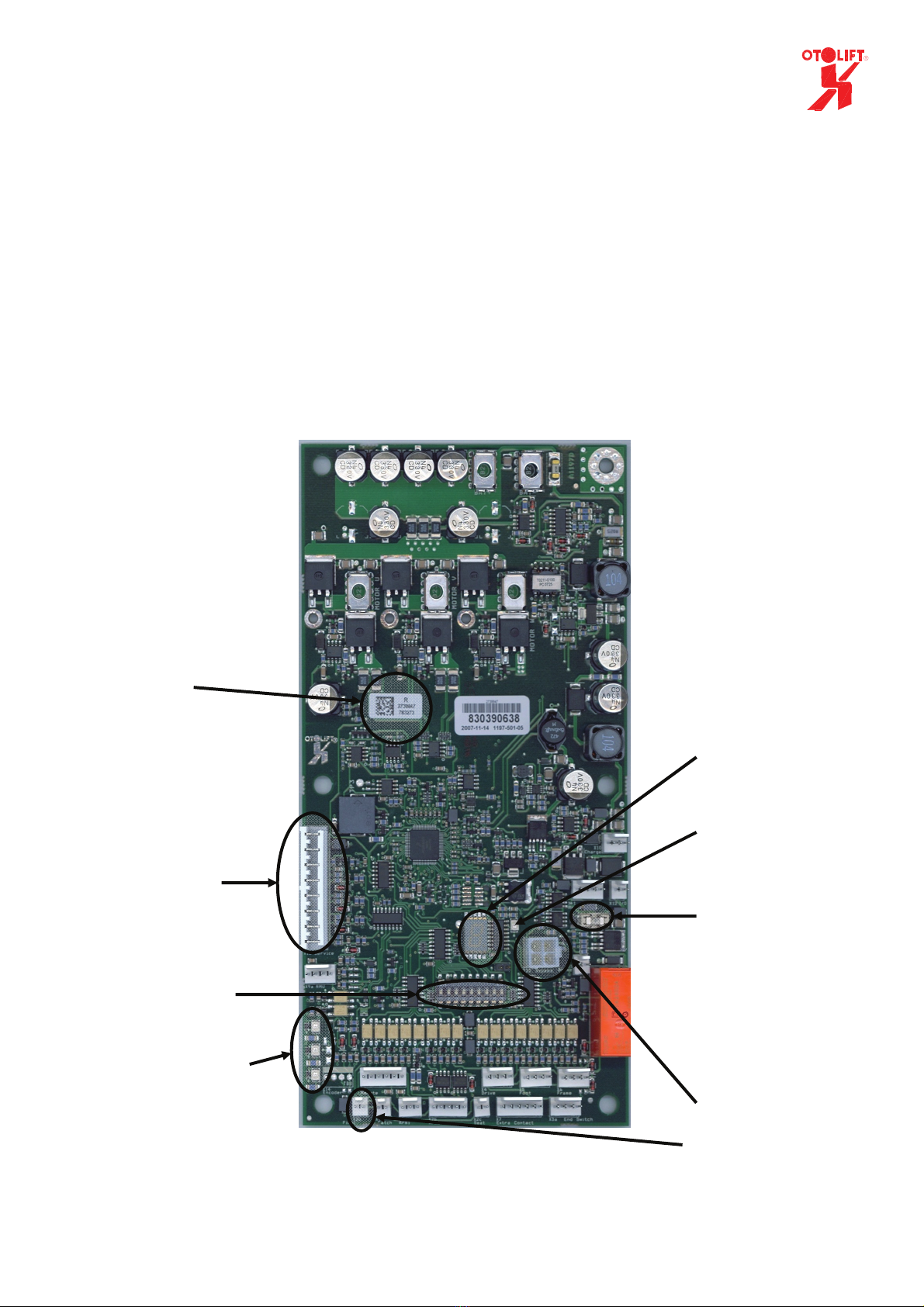
3. Dipswitches on the circuit board
The dipswitches on the circuit board have their own logic functions.
Dipswitch 1= on => The rotation monitor unit is monitored on its functionality.
If the rotation monitor (RMU) does not give an alternating signal,
during 30 cm of moving the lift, the lift stops.
The lift will drive further by re-controlling it.
If the dipswitch is off and a rotation monitor unit is connected, the
PCB will see this as an incorrect combination. Every time when the
signal from the RMU alternates the chair is stopped.
Dipswitch 2 = on => Use for future options. (functionality is already implemented)
If the lift has reached an endpoint and has stopped, the switched logic
output X11 will be active as long as the lift is operated.
When dipswitch 2 = off, output active on upper and lower endpoint.
When dipswitch 2 = on, output only active on upper endpoint.
(If setting dipswitch 9 is correct)
If the lift is operated, the switched logic output X12 will be active as
long as the lift is operated.
When dipswitch 2 = off, output active only when swivel switch
and armrest-contact are closed and control is operated.
When dipswitch 2 = on, output always active when control is
operated.
Dipswitch 3 = on => When the lift has not seen the voltage of the transformer for 1 or 8
hours the lift will go into sleepmode. (low current consumption)
When the dipswitch is on, the sleepmode will be activated after 8
hours instead of the standard 1 hour.
Dipswitch 4 = on => When an extra charge or stoppoint has been programmed, the lift will
stop on this point when it is controlled by a remote-control.
Dipswitch 5 = on => When an extra charge or stoppoint has been programmed, the lift will
stop on this point when it is controlled by the armrest-control.
Dipswitch 6 = on => The beeper will give a continuous alternating alarm signal (1 Hz),
when the lift has not seen the voltage of the transformer for a period of
time after controlling the lift.
When the dipswitch is on, the delay to this alarm is 2 minutes instead
of the standard 15 seconds.
Dipswitch 7 = on => For future developments. Functionality until now not implemented.
Dipswitch 8 = on => The standard lift (130 kg) has its own maximum torch settings.
In future developments, we can give more torch to the motor by
switching this dipswitch on.
Never adjust this dipswitch in the standard 130 kg application.
Dipswitch 9 = on => Depending if a rail is mounted on the left or right side of a staircase
the logic of the remote might have to be reversed.
When the dipswitch is on, the remote-control is adjusted for right rail.
When the dipswitch is in the standard off position the remote-control
is adjusted for a left rail.

10
4. Programming the chairlift
4.1 Need to know before programming
The chairlift must always be programmed, when moving to the right. (seen from user position)
Thus a lift which is mounted on the left side of the stairs, must be programmed from the endpoint at
the top till the endpoint of the bottom, and a lift which is mounted on the right side of the stairs, must
be programmed from endpoint of the bottom till the endpoint at the top.
Be careful, when using the servicebox in bypassmode the lift only stops when an endswitch is
operated. (Bypass see chapter 5.1 page 12)
When an overspeed governor is mounted on the chairlift, and the bypass-connector is connected and
activated, the lift will not stop when the overspeed governor contact (catch) opens,.
Please keep this in mind.
Servicebox control
S= Service => switch upwards = on / down = off
T = Teach in => switch upwards = on / down = off
L = move Left => switch operated = on
R= move Right => switch operated = on
1 2 = speed 1or 2
C = Hold to Run Button Bypass Connector
Before programming, always check to make sure the lift stops at the endswitches.
Service + Left: the lift must stop when safety-cap endswitch left is controlled.
Service + Right: the lift must stop when safety-cap endswitch right is controlled.
The speeds must be set before starting programming the lift.
The position of the potentiometer is related to the speed.
With the switch below the potentiometers (1 2) you can choose the potentiometer-speed .
To see the actual set (potentiometer) speed, move the lift by Service and Left or Right.
During movement in service mode you can adjust the speeds.
Do not adjust the potentiometers during programming procedure.

11
4.2 Programming the chairlift
Start programming procedure when ‘potentiometer’ speed is set.
Programming procedure:
1 Switch on Service.
2 Move the chairlift to the left by operating Left (servicebox), until it stopped against the buffer
3 Release Left
4 Switch off Service.
5 Choose speed 1 or 2 (switch 1 2) speed should be set before programming procedure
6 Switch on Teach
7 Operate Right (on servicebox) (the chairlift begins to move).
Keep Right operated till point 10.
8 If necessary, switch over the speed by operating switch 1 2.
(Max of 35 times of switch over in speed possible)
9 If the chairlift has stopped against the other buffer, the system beeps 5 times.
10 Release Right
11 Switch off Teach
12 Remove the connector from the service box if there are no additional charging points.
If an extra charge point has been installed on the rail, the chair can be programmed in for this.
Programming procedure for extra charge-point(s)
13 Switch on Service
14 Move the chairlift to the extra charging point.
15 Park the chairlift exactly in the middle of the charging point.
16 Leave the system on Service and switch on Teach mode, the system will beep once.
17 Switch off Teach.
18 Switch off Service.
19 Remove the plug from the service box.
If a second extra charging point has been installed, this can be programmed into the chairlift as well.
Repeat points 13 through 19, the system will beep twice at point 16. (3th charging-point 3 times...etc.)
In total 5 extra charging points/stoppoints can be added.
Extra charging-points can not be deleted.
When a incorrect charging-point has been programmed in, start at point 1.
You can choose for which control the chairlift should stop on the extra charging point(s)
Dipswitch 4 = on, the lift will stop when operated on by the remote-control.
Dipswitch 5 = on, the lift will stop when operated on the armrest.
Dipswitch 4 + 5 = on, the lift will stop when operated by the remote-control as well as on the armrest.
Activate alarm when controlled by remote
Alarm during movement when controlled by remote can activated or de-activated by controlling L+R
1sec on the servicebox. (Service and/ or Teach should be in off position)
This functionality is added in software version c40 or higher.
Only start programming the lift, when the lift is operating OK (without bypass-connector.)
The hinge should stand in the hinge out position.
Keep the transformer connected to the mains-voltage

12
5. Bypass-connectors and interconnections on the PCB
5.1 Bypass-connectors
When you want to move an incomplete or defect lift you need the Bypass-connectors.
They are attached to the service-box.
Connect the 4 pole connector to x15 (bypass) and the 2-pole to x3b (limit)
With these connectors you will be able to override all safety-contacts, except for the endswitches.
Activation of override is done, by holding the red C button on the service box.
When you disconnect the Bypass, do not forget to put jumper back to X3b (see chapter 5.2)
Programming can not be done when this connector is connected.
When connected and activated, the lift moves with a maximum of 5cm/s. (C38 software or higher)
When bypass is activated, you will not be able to move the lift, by “normal” control.
(armrest or remote). When you try to do this, the display will show (8-8-8-8-11).
(See headline 8888 error mechanic-needed-beep).
If the chair is functioning properly, you can also use the service box without the bypass-connector.
The bypass connector also overrides the overspeed governor safety-contact. (Catch)
5.2 Interconnections on the PCB
Some connectors are not used in the type 87 application.
In this case we use jumpers to make the interconnection.
X3b is standard interconnected by a jumper.
When this interconnection is forgotten the display will show the error 8-8-8-8-y and 2 LED’s will be
off. (see chapter 9.2, LED’s on the PCB)
When no 1 channel receiver, folding rail PCB and/or SENSOR is connected, 2 extra connections
should be made on X7, by using jumpers. See foto.
5.3 Logic of pin-numbers
All pcb connectors are named with an x number.
The x is always positioned at the side of connection 1 / pin-number 1
In the upper foto, the interconnections on X7 are made on pin 3 & 4 and 5 & 6.

13
6. Charging the batteries
If the chairlift is on, and the batteries are being charged, the LED on the armrest is on continuously.
When the chair is on and the batteries are NOT being charged the LED will blink with a frequency of
1 Hz.
6.1 Charging-points
The voltage for charging the batteries is interconnected through the charging contacts.
A detail drawing of the connections of the charging-points is attached. (drawing 86900 LD eng)
6.2 No-charging-alarm
When the lift is not moving and is not receiving any charging voltage, the lift will start beeping after
15 seconds or 2 minutes.
Frequency of the beep = 1Hz
If the lift gives the no-charging-alarm you can stop this alarm by controlling left or right for 0,5
second. (remote or armrest).
When the lift has been used, and the batteries are still not charged after it stopped, the alarm will
sound again.
The time to no-charging-alarm can be set by dipswitch 6.
6.3 Transformer / on board charging-circuit
The main PCB has its own charging-circuit on board.
Because of this we can charge more accurate, which results in a longer lifetime of the batteries.
The maximum charge-current is 1,1A .
The transformer of the type 87 is NOT a battery-charger. You can not and may not use this
transformer for charging batteries directly.
Only use this transformer in combination with the 86900 or 09000 (jade) PCB.
Visa versa, you can not use a standard battery-charger, to charge the batteries when a type 86 main
PCB is connected.
The transformer must be fused with a 1,6 Ampere Fuse (glass-fuse 5x20)
NEVER apply a fuse with a higher value.
Always use the special 24V DC transformer which is delivered by Otto Ooms BV.

14
6.4 Battery-fuse
For protection of all electronics a main-fuse is put in series with the batteries.
The fuse-holder is placed as an interconnection between the batteries
In case of standard 130 kg lift a 20A blade fuse is needed.
6.5Sleepmode
When the lift has not been charged for 1 or 8 hours it will go into a sleepmode.
In sleepmode, the current-consumption is approximately 10 mA.
If the lift is in the sleepmode, you can simply wake it up by controlling the armrest control left or
right. After waking up the lift can be used directly.
The time till sleepmode can be set by dipswitch 3.
6.6 Lift will not be used for a longer period.
When, for example, a user goes on vacation, we advise to keep the transformer connected to the mains
voltage.
In this situation the charging-circuit will keep the batteries in good condition.
Only switch off the armrest button.

15
7. Remotes/transmitters and receivers.
The chairlift has a separated receiver (PCB) built in for remote-control.
In case of a powered sliding hinge 2 extra remotes and 1 receiver is used for controlling the hinge in
and out.
Also an extra 1-channel transmitter (on the hinge) and 1-channel receiver (in the chairlift) is applied
for hinge-is-down command.
Before using the remote you have to teach them in and/or adjust the dipswitches.
The battery-voltages has to be connected, when you want to teach them in.
7.1 Teaching the 2-channel remotes into a 2-channel receiver
1. Open the cover of the receiver-box.
2. Operate the switch on the receiver once. (LED lights up).
3. Operate within 30 seconds the up or down switch of the remote which should be programmed
in. The LED will go off.
(Battery on remote should be connected.)
4. The up and down signal of the remote now will be ‘seen’ by the receiver.
5. Repeat step 2 and 3 for the next remote.
(programming up to 16 remotes is possible.)
2-channel receiver 2-channel remote
•For deleting the transmitters, keep switch on the receiver operated, until the LED dims. (5
seconds)
•With the dipswitches, the send- and receive frequency can be changed.
•The dipswitches on the remotes and the receiver have to be adjusted in the same position.
(always both on or both off)
7.2 Reverse logic up/down of 2 channel remote
Depending on whether a rail is mounted at the left or right side of a staircase the logic (up/down) of
the remote might have to be reversed.
When dipswitch 9 = on, the remote-control is adjusted for right rail.
When dipswitch 9 = off, the remote-control is adjusted for left rail. (standard)
Dipswitches
LED
Switch
Switch
up/down

16
7.3 Adjusting the dipswitches of the 1-channel transmitter and receiver
To make the 1-channel receiver work with the 1-channel transmitter you have to adjust the dipswitches
of both in the same way.
1-channel receiver 1-channel transmitter
The receiver and transmitter always have the same dipswitch settings, when they come from the
manufacturer.
We recommend to adjust the dipswitch always to prevent that a signal from another hinge can give a
false hinge-is-down command.
7.4 Types and type numbers
2-channel remote = SKE2MLV
2-channel receiver = EKE2MLV
1-channel transmitter = SFB1LV
1-channel receiver = EFB1LV
Dipswitches

17
8. Powered hinge
At this moment we have 2 different powered hinges.
The powered sliding hinge needs less space then the powered folding hinge when folded in.
8.1 Powered sliding hinge
The powered sliding hinge uses extra remote-controls for moving the hinge up/down.
A 1-channel transmitter and receiver are used for ‘hinge is down’-command.
The transmitter is battery-buffered via 2x 9V recharge-able batteries on the hinge PCB.
The hinge can only be controlled when a chair is on the charge-point.
It uses the battery of the chair as powersupply.
A detail drawing of the connections of the sliding hinge is attached. (drawing 86900 SS eng)
8.2 Powered folding hinge
The folding hinge is controlled by an extra PCB in the chairlift itself.
When you control the lift on the armrest or on a remote, the extra PCB in the chair (ssp 008 v3)
commands the PCB under the rail (ssp 007 v3) to fold the rail out.
When the hinge has folded out, the PCB near the hinge commands the PCB in the lift that it is safe to
drive.
If the chair is stopped on a charge-point the hinge will fold in automatically.
A detail drawing of the connections of the folding hinge is attached. (drawing 86900 KS eng)
The working of the folding rail is described in chapter 9.9
Note that the transformer is not connected directly to the charge-point, but is (and should be)
interconnected through the PCB ssp 007.

18
8.3 Warning for older type of hinge PCB’s.
Some of the older type hinge PCB’s are not compatible to the type 87, and some of type 87 parts are
not backward-compatible to older types of lifts.
PCB’s which you can/ may use in combination with the 86900 PCB and transformer are;
- Sliding hinge ssp 042 V6 (mounted in the cover of the hinge) (used since March 2007)
- Folding hinge ssp 007 V3 (mounted under the rail) (used since March 2008)
- Folding hinge ssp 008 V3 (mounted in the chair) (used since March 2008)
8.4 Sliding hinge uses too much current. (friction in application.)
To prevent melting of the 5A fuse , when the hinge-application gives too much friction, we added
electronics which measure the output current on x10 pin 3.
When the current consumption of the hinge becomes too high, the electronics will switch off the
power for approximately 1 sec.
This can be repeated 10 times. Then the PCB shows error 8-8-8-8-J and all output voltages will be
switched off.
You can reset this error by controlling the lift on the armrest for 1 second.

19
9. Error-handling for mechanic
9.1 Diagnostic display
A display on the PCB shows the actual error. More detail info of this display errors is attached to this
document. (attachment 87900 error eng).
The display can show the following errors.
S witch in arm rest is in off position
Switch in armrest is on (main safety-line OK)
Swivelseat-switch is operated
Extra contact is not interconnected (by jum pers, 1-channel receiver or ssp 008 v3 and/or SENSOR)
Current consumption on x10-3 hinger than 100 mA
Lift is operated on two places
Lift did not charge for 1 or 8 hours. (depending setting dipswitch)
Lift was in sleepmode
Mechanic-needed-error. (1 till 12 gives fast beep).
Safety drive unit right controlled
Safety drive unit left controlled
S afety footrest right controlled
S afety footrest left controlled
Safety frame right (or underside rail left) controlled
S afety fram e left (or und erside rail right) controlled
Lift is on an endpoint and the endswitch in opposite direction is operated.
Endswitch right is controlled
Endswitch left is controlled
High load "overcurrent" (too much load on the chairlift)
Low battery-voltage
Temperature PCB too high
Rotation monitor unit defect (overspeed governer). (dipswitch 1 setting OK?)
Error 1 (h) Too high voltage on X10-1. (wiringfault of transformer/chargepoint)
Error 2 (o) Overvoltage on batteries during charging or movement.
Error 3 (c) Relay error or wiring brake not OK or connected (also see error 15 and 16)
E rror 4 (n) O ther voltage s are interconnected in safetyline
Error 5 (N) Interconnection between safetyline left and right
Error 6 (U) PCB defect (H SL or H SR internally shortcircuit)
E rro r 7 (u ) P C B d efe ct (H SL o r H S R d o no t fu nc tion )
Error 8 (y) smd fuse, overspeed governer (catch) or input limit interconnection not OK
Error 9 (q) One of the contacts on X7 do not work synchronised (defect contact?)
Error 10 (e) Defect encoder. (not applied/used in 86 model)
E rror 1 1 (1 1) B yp ass-co nn ector is still con nected (a nd a ctive).
Error 12 (reverse t) Batteries did not reach max batterie voltage (after 3xC).
Error 13 ( J) 10x high output current x10-3
Error 14 ( j) Internal defect on PCB
Error 15 ( r )Relay does not become active. (C38 software or higher)
Error 16 ( r) W iring brake not connected. (C38 software or higher)
If for example the display shows 2, this means that the swivelseat-switch is controlled, or that the
wiring to this switch is defect.
In combination with the detail drawing of the wiring (attachment 86900 CW eng) it should be easy to
solve the problem, if the problem is related to the wiring.
An 8888x error is shown as a 4x blinking eight and then failure code .
All 8888x errors will generate a fast beep (5Hz).
Exception for error 8888J (error 13) This one does not generate the fast beep.

20
9.2 LED’s on the PCB
There are 4 LED’s mounted on the PCB.
The 3 LED’s left bellow are mounted for indication of the status of the 375 mA SMD fuse, contact of
overspeed governor (catch) and limitswitch/jumper. (LED 1, 2 & 3)
The LED near the display shows the status of the PCB. (LED 4)
LED 1,2 & 3 on = Fuse 375 mA (F1) safetyline & contact overspeed governor (catch) and limitswitch (limit) OK.
LED 1,2 & 3 off = Fuse 375 mA (F1) safetyline defect / sleepmode / shortcircuit x10-3 to ground.
LED 2 & 3 off = Limitswitch (limit) is operated / jumper as interconnection not connected.
LED 2 off = Contact overspeed governor (catch) is operated.
LED 4 on = OK
LED 4 off = 5A fuse defect/ no battery-voltage
LED 4 flashes = Chairlift is in sleepmode
9.3 Error-log
The PCB stores the errors in its memory.
By using the buttons left and right on the servicebox you can read out the error-log.
Facts & functions of error-log
- Control right => read the stored errors backwards
- Control left => start at latest stored error
- Control left for 10 sec. => delete error-log
- Every 24 hours (when not in sleepmode) the log stores a underscore
- Errors are only stored when the lift is controlled by armrest left/right or remote up/down.
- When the lift has not moved, the same error will stored once.
- When the lift has moved, the same error can be stored more then once.
- Maximum of 20 errors or days can be stored.
- The end of the error-log is shown as a minus
Please note that the underscore is not real time. The system only stores the underscore when the
system has been active for 24 hours.
Example 1
The lift has been active for more then 20 days. (today it is Monday)
A user complains that the lift has stopped several times during movement on Wednesday and Friday.
When the error-log has read out the display could show:
Note that the first error you read is the most recent one.
_ _ _ 2 2 2 _ _ 2 2 2 2_ _ _ _ _ _ _ _ -
or
_ _ 2 2 2 _ _ 2 2 2 2_ _ _ _ _ _ _ _ _-
Display-error 2 means that the swivelseat-switch was operated during operating the lift.
In this case it is obvious that the problem has to be found in the wiring or the adjustment of the switch.
Other manuals for 87
1
Table of contents
Other OTOLIFT Stairlift manuals