IKAR Full Body Harnesses Technical manual

1
Prüfbuch und Gebrauchsanleitung
INSTRUCTIONS FOR THE USE
AND INSPECTION RECORDS
IKAR GmbH
“Auanggurte/Haltegurte”
“Full Body Harnesses”
Nach EN 361:2002,
mit optionaler Haltefunktion nach EN 358:2000 und
Schulteraufhängung nach EN 1497:2007
acc. to EN 361:2002,
with optional Work Positioning Waist Belts
to EN 358:2000 and
Overhead Rescue Attachments to EN 1497:2007
PRÜFBUCH IMMER BEIM GERÄT AUFBEWAHREN !
VOR GEBRAUCH ANLEITUNG SORGFÄLLTIG LESEN !
ALWAYS KEEP THIS BOOKLET WITH THE DEVICE!
CAREFULLY READ THESE INSTRUCTIONS BEFORE USING THIS PRODUCT!
GR
GB FR IT
D NL PL DK SE FI NO HU
ES

32
Gurttyp / Safety harness / Sit Harness / Rescue Harness type:
Serien-Nr. / Serial no:
Typenbezeichnung / Type designation:
Herstelldatum / Date of manufacture:
Erstbenutzung / Date of fi rst use
Kaufdatum / Date of purchase:
Prüfung / Inspection Datum / Date
Gurtband allgemein - ist nicht:
Webbing Gener - not:
zerschnitten, eingerissen oder eingekerbt
cut, torn or nicked
abgescheuert
abraded
Hitze geschädigt
heat damaged
verschmutzt
contaminated
entfärbt
discoloured
Nahtbild - ist nicht:
Stitch Patterns - not:
gebrochen oder abgescheuert
broken or abraded
gerissen oder lose
pulled or loose
Metallbeschläge - sind nicht:
Metal Fittings - not:
korrodiert
corroded
gerissen oder verformt
cracked or deformed
ordnungsgemäß funktionierend
mis-functioning
Verschlüsse - sind nicht:
Buckles - not:
ordnungsgemäß funktionierend
mis-functioning
verbogen oder deformiert
correct or deformed
Kunststoffbeschläge
Plastic Fittings
vorhanden
preent
nicht beschädigt
not damaged
Sonstiges
Other
Typenschild vorhanden und lesbar
Label present and legible
Reinigung durchgeführt
Cleaning carried out
Geprüft von /Inspected by
Nächste Prüfung fällig
Next inspection due
Erstabnahme
Initial check
Konformitätserklärung / Conformity: http://ikar-gmbh.de/index.php/de/service/download
Aufzeichnung der Sicht- und Funktionsprüfung / Record of visual and tactile inspection

33
Diese Gebrauchsanleitung mit Prüfbuch ist Bestandteil des Sicherheitssystems, und alle Benutzer sollten sich vollumfänglich mit den
Inhalten vertraut machen. Es sollte an einem sicheren Ort aufbewahrt werden und jederzeit für alle Benutzer frei zugänglich sein.
Nach Entfernung dieses Produkts aus der Verpackung sollte die Tabelle auf der gegenüberliegenden Seite mit den Angaben auf
dem Typenschild ausgefüllt werden. In der Tabelle unten sollten alle detailliert aufgezeichneten Prüfungen - anhand der in der
Risikobewertung festgelegten Intervallen - mindestens jedoch alle zwölf Monate, aufgezeichnet werden.
This user manual and operating instructions are part of the safety system and all users should be totally familiar with its contents. It should be
kept in a safe place and be freely available to users at all times. When this product is removed from it‘s packaging the table on the opposite page
should be completed taking the information from the product label. The table below should be used to record all Detailed Recorded Inspections at
a frequency deemed through risk assessment but at least every 12 months.
Datum / Date

544
Inhaltsverzeichnis
Directory - Contenidos - Sommaire - Contenuto - El indice - Conteúdo - Inhoud - Zawartość
Conținutul - Indholdet - Innehåll - Kirjan sisällön - Innholdet - Tartalmát - περιεχόμενα
Prüfbuch / Log book ............................................................................... 2 - 3
Kennzeichnung / labeling ........................................................................... 5
DEUTSCH ......................................................................................... 5 - 10
ENGLISH......................................................................................... 11 - 16
ESPAÑOL ........................................................................................17 - 22
FRANÇAIS.......................................................................................23 - 28
ITALIANO........................................................................................ 29 - 34
NEDERLANDS................................................................................ 35 - 40
POLSKI ........................................................................................... 41 - 46
DANSK............................................................................................ 47 - 52
SVENSK.......................................................................................... 53 - 58
SUOMEKSI ..................................................................................... 59 - 64
NORSK............................................................................................ 65 - 70
MAGYAR......................................................................................... 71 - 76
ΕΛΛΗΝΙΚΑ...................................................................................... 77 - 82

5
DEUTSCH
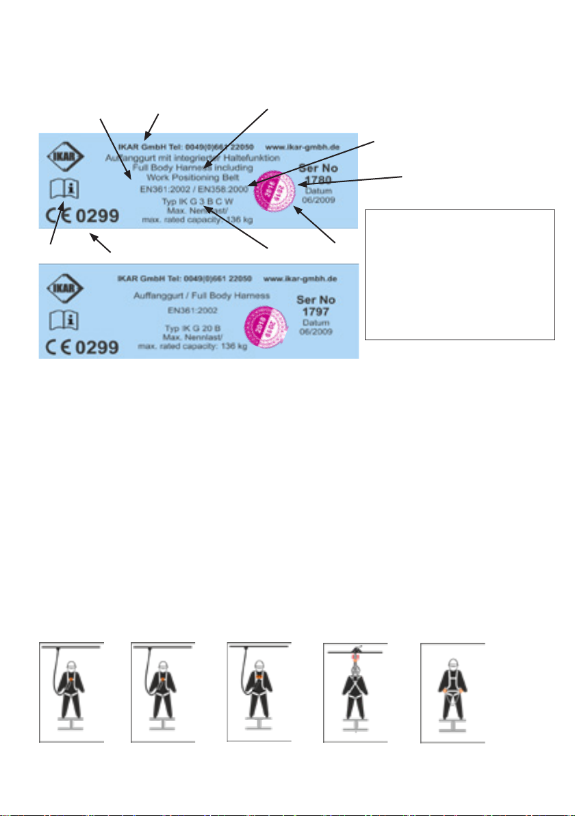
Typenschild auf dem Au anggurt, das bei Benutzung des
Au anggurtes aufgebracht, intakt und lesbar sein muss.
1. Überwachende Stelle
2. Seriennummer
3. Produktbezeichnung
4. IKAR GmbH ProduktCode / Typ / Variante
5. Norm/Jahr
6. Gebrauchsanwesung bachten
7. Herstelldatum
8. Hersteller
9. Nächste Revision
Legende der Produktcodes der Au anggurte
IK = IKAR GmbH
G = Auffanggurt
1 = Einzelpunktgurt
2 = Zweipunktgurt
20 = Zweipunktgurt
3 = Zweipunktgurt
A = Auffangöse aus Kohlenstoffstahl vorne und hinten, Gelenk-Schnellverschlüsse
B = Auffangöse aus Kohlenstoffstahl hinten, Schnellverschlüsse aus Stahl
C = hintere Auffangöse aus Kohlenstoffstahl (NOs), Auffangschlaufen vorne am Gurtband
R = Schulteraufhängung
W = integrierter Haltegurt
Diese Bedienungsanleitung deckt die folgenden Produkte der IKAR GmbH ab:
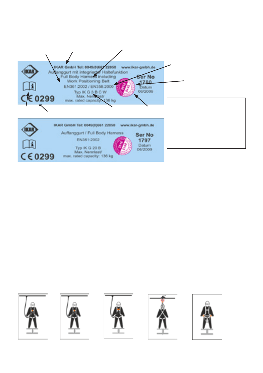
IK G 1 Einzelpunkt-Auffanggurt (Rücken- Auffangöse)
IK G 2 Zweipunkt-Auffanggurt (Rücken- Auffangöse und vordere Auffangöse / Auffangschlaufen)
Stahl-Rücken-Auffangöse
mit “A” bezeichnet
Beidseitige Stahl-HalteösenSchulteraufhängung
bezeichnet mit “A”
2 Auffangschlaufen im
Brustbereich, bezeichnet
mit “½ A”
Stahl-Steigschutzöse
mit “A” bezeichnet
DEUTSCH
Dieser Auffanggurt gehört zur “Persönlichen Schutzausrüstung gegen Absturz” (PSA gA) und stimmt überein mit den grundlegen-
den Anforderungen der Verordnung (EU) 2016/425.
1
2
9
8
5
4
3
7
6

6 7
DEUTSCH
IK G 3 B Zweipunkt-Auffanggurt (Rücken- Auffangöse und vordere Auffangschlaufen)
Beidseitige Halteösen (IK G 3 BW / IK G 3 BCW)
IK G 20 Zweipunkt-Auffanggurt (Rücken-Auffangöse und vordere Auffangschlaufen)
Beidseitige Stahl-Halteösen
Stahl-Rücken-Auffangöse
mit “A” bezeichnet
2 Auffangschlaufen im
Brustbereich, bezeichnet
mit “½ A”
Stahl-Rücken-Auffangöse
mit “A” bezeichnet
IK G 2 IK G 2 / IK G 3 IK G 20 IK G 1 / IK G 2
Die Auff anggurte IK G 1 / IK G 2 / IK G 3 / G 20 sind nach EN 361:2002 zugelassen. Sie sind für den Einsatz in
Auff angsystemen von persönlichen Absturzschutzausrüstungen (EN 363) vorgesehen und sind damit in Verbindung
mit anderen Bestandteilen der persönlichen Schutzausrüstung gegen Absturz (PSA gA), z. B. mit energieabsorbie-
renden Verbindungsmitteln EN 354/EN 355, anzuwenden.
IK G 1 umfasst zwei Basisversionen; die Variante ergibt sich aus der Ergänzung A bzw. B vor dem Produktcode
IK G 2 umfasst drei Basisversionen; die Variante ergibt sich aus der Ergänzung A, B oder C vor dem Produktcode
IK G 20 ist eine eigene Version mit vorderen Auff angschlaufen; die Variante ergibt sich aus der Ergänzung A oder B
vor dem Produktcode
IK G 3 ist eine eigene Version mit rechtwinklig über dem Oberschenkel verlaufender Beinberiemung und einem
Bauchgurt
Variante A Auff angösen aus Stahl, justierbare Schultergurte, Brustgurt und Beinschlaufen über einen Steckver-
schluss.
Variante B Auff angösen aus Stahl, justierbare Schultergurte, Brustgurt und Beinschlaufen über einen Schnellver-
schluss
Variante C hintere Auff angöse aus Stahl, Auff angschlaufen vorne (müssen zusammen verwendet werden),
justierbare Schultergurte, Brustgurt und Beinschlaufen über einen Schnellverschluss
Alle IKAR Auff ang- und Haltegurte sind aus einem Polyestergurtband hergestellt.
Die Punkte der Auff angösen sind deutlich mit dem Buchstaben „A“ gekennzeichnet; dies ist jeweils der Punkt, mit
dem die Bestandteile des Auff angsystems der PSA gA verbunden werden darf. Werden bei den Auff anggurten IK
G 2C / IK G 3 BC / IK G 20 die vorderen Befestigungspunkte, die aus zwei Auff angschlaufen ( mit ”½ A“ bzw. A/2
gekennzeichnet) bestehen verwendet, müssen beide gemeinsam mit dem Verbindungselement EN 362 (Karabiner)
des Auff angsystems mit energieabsorbierendem Einzelteil verbunden werden. Andere Ösen oder Schlaufen dürfen
zu Auff angzwecken nicht benutzt werden.
IK G 1 und IK G 2 (alle Basisversionen) können auch mit einer Schulteraufhängung ausgerüstet werden, um sie
in geschlossen Räumen bzw. in der Nähe von vertikalen Anwendungen mit begrenztem Platz zu verwenden; sie
sind durch ein „R“ vor dem Versions- bzw. Typ-Code gekennzeichnet. Die Schulteraufhängung wurde geprüft
und gemäß CE nach EN 1497:2007 und EN 361:2002 zugelassen. Die Schulteraufhängung sollte jedoch nur als
Absturzsicherung genutzt werden, wenn sie mit einem Höhensicherungsgerät mit Rettungshubeinrichtung EN 360/
EN 1496 mit automatischem Einzug und eingebautem Rückholmechanismus verbunden ist, wobei das einziehbare
Verbindungsmittel des Gerätes direkt von oben kommt. Dieser Punkt der Schulteraufhängung ist NICHT geeignet
zur Nutzung mit energieabsorbierenden Verbindungsmitteln EN 354/ EN 355 oder mitlaufenden Auff anggeräten
einschließlich beweglicher Führung EN 353-2.
DEUTSCH

7
DEUTSCHDEUTSCH
Dazu bzw. als Alternative können die IK G 1, IK G 2 (Basisversionen) und IK G 3 B mit einer integrierten
Haltefunktion mit zwei Halteösen an den Seiten ausgestattet werden; sie sind durch ein „W“ vor dem Versions- bzw.
Typ-Code gekennzeichnet. Die Haltefunktion wurde geprüft und nach EN 358:2000 zugelassen.
Benutzer dieses Au anggurtes der IKAR GmbH
• müssen sicherstellen, das die maximale Nennlast von 136 kg nicht überschritten wird
• müssen hinichtlich der Benutzung und der Prüfbestimmungen vor der Benutzung unterwiesen werden
• müssen sicherstellen das der Auff anggurt nur mit einem persönlichen Absturzsystem nach EN 363
verwendet wird, sodass die mögliche Absturzhöhe auf ein Minimum begrenzt wird. Vor der Verwendung des
Absturzschutzsystems ist auf einen ausreichenden Freiraum unterhalb des Benutzers zu achten, so dass
im Falle eines Sturzes kein Aufprall auf den Boden oder ein anderes Hindernis möglich ist. Zur Ermittlung
des erforderlichen Freiraumes sind die Vorgaben aus den Gebrauchsanleitungen der einzelnen Bestandteile
des verwendeten Absturzschutzsystems zu beachten. Bei der Kombination der einzelnen Bestandteile des
Absturzschutzsystems ist darauf zu achten, das die Funktionen der einzelnen Elemente uneingeschränkt
erhalten bleiben und sie sich nicht gegenseitig beeinträchtigen
• Bei Nichtbeachtung der Gebrauchsanleitung und der Sicherheitshinweise besteht Lebensgefahr. Im Falle eines
Sturzes ist ein Hängen der Person länger als 15 Minuten auszuschließen (Schockgefahr)
• dürfen ihn nicht benutzen, wenn sie Beschwerden haben, die ihre Sicherheit im normalen und im
Notfalleinsatz beeinträchtigen können;
• müssen sicherstellen, dass ein Notfallplan vorhanden ist, wenn der Auff anggurt für die Absturzsicherung
eingesetzt wird;
• dürfen keine Änderungen, Ergänzungen oder Reparaturmaßnahmen am Auff anggurt vornehmen;
• müssen sicherstellen, dass der Auff anggurt nicht außerhalb der eingeschränkten Bereiche eingesetzt
wird, dass er ausschließlich für die beabsichtigten Zwecke genutzt wird, und dass der Benutzer für
diese unterwiesen wurde;
• müssen die Kompatibilität anderer mit diesem Auff anggurt verwendeten Bestandteile der persönlichen
Schutzausrüstung gegen Absturz (PSAgA) sicherstellen, wenn sie zu einem Auff angsystem montiert werden;
• müssen beachten, die geeeigneten Zubehöre wie z.B. Schulterpolster und Werkzeugtaschen die sichere
Funktion des Auff anggurtes nicht beeinträchtigen;
• müssen beachten, das Werkzeugtaschen nur an die vorgesehenen Ösen der Rückenstütze befestigt werden;
• müssen beachten, dass das mitgeführte Material in den Werkzeugtaschen ein Gewicht von 15 kg nicht
überschreitet und die Nennlast von 136 kg inkl. Benutzer nicht überschritten wird;
• müssen sich auch an die Gebrauchsanleitung der anderen Bestandteile halten;
• müssen sicherstellen, dass der Einsatz mehrerer Bestandteile der PSA gA keine Gefahr darstellt, welche die
sichere Funktionsweise eines der Bestandteile beeinträchtigt oder behindert;
• müssen vor dem Einsatz des Auff anggurtes sicherstellen, dass er in funktionsfähigem Zustand ist;
• müssen den Auff anggurt sofort aus dem Verkehr ziehen, wenn bezüglich seines Zustands für die sichere
Benutzung Bedenken bestehen, oder wenn er einer Sturzbeanspruchung ausgesetzt war;
• müssen Gefahrenquellen erkennen, die die Leistungsfähigkeit des Auff anggurtes beeinträchtigen oder zu einer
Fehlfunktion desselben führen können; zu diesen Gefahrenquellen gehören:
• extreme Temperaturen (unter -15° C und über +50° C)
• aggressive Umweltbedingungen, wie z.B.
– Sand und Split
– heiße Oberfl ächen
– off enes Feuer
– Schweißfl ammen
– Funken
– Hochfrequenzeinfl üsse
– Kontakt mit scharfen Kanten
– scheuernde Oberfl ächen
– Chemikalien
• müssen die Benutzung des Auff anggurtes sofort einstellen, wenn dieser eine der vorgenannten
Gefahrenquellen ausgesetzt oder beschädigt wurde, bis er von einer quali zierten Person geprüft wurde;
Gebrauchsanleitung

8 9
DEUTSCH
• Die Lebensdauer eines Auff anggurtes hängt von zahlreichen Faktoren ab, z. B. Umweltbedingungen
bei der Benutzung, Häu gkeit der Benutzung, Einhaltung von Lagerungs- und
Wartungsbestimmungen. Der Auff anggurt kann nur maximal 12 Jahre nach dem Herstelldatum verwendet
werden.
• Benutzer dieses Auff anggurtes der IKAR GmbH müssen zudem sicherstellen, dass das Datum der ersten
Nutzung in diesem Prüfbuch eingetragen wurde
• Bei Wiederverkauf dieses Auff anggurtes der IKAR GmbH müssen sämtliche Bedienungs-, Wartungs- und
periodischen Prüfanleitungen in der Landesprache vorhanden sein.
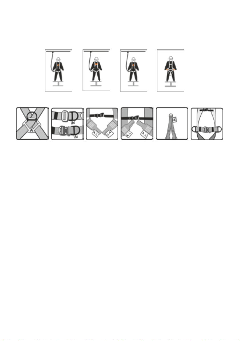
Bei der Anpassung dieses Au anggurtes müssen die Benutzer sicherstellen, dass:
• der Auff anggurt so justiert ist, dass die Rücken-Auff angöse zwischen den Schulterblättern liegt,
• alle Gurtbänder fl ach am Körper aufl iegen und nicht verdreht sind,
• die Schultergurte an die Länge angepasst werden, und zwar nach oben durch den Justierverschluss, damit
der Brustgurt, wenn er verbunden ist, über dem Brustbein liegt,
• die Beinschlaufen an die Länge angepasst werden, damit sie eng in der Leiste aufl iegen,
• das Gesäßband des Typs IK G 3 unter dem Gesäß sitzt und die Länge durch die seitlichen Beschlagteile
angepasst ist, die Beinberiemung eng und rechtwinkelig über den Oberschenkel verlaufen,
• der Bauchgurt nach der Anpassung festgemacht und um den Bauch gelegt ist
• die vorderen Auff angschlaufen durch die Justierverschlüsse so angepasst sind, das sie in Höhe des
Brustbeins sind,
• alle Verschlüsse auf korrekte Funktion hin geprüft wurden,
• die Schnellverschlüsse fl ach aneinander liegen und ein Teil durch das andere läuft, bei den
Schnellverschlüssen die Zunge des einen Teils sicher und fest in dem anderen Teil ist,
• die Enden des Gurtbandes nach dem Zusammenführen der Verschlüsse und dem Justieren
des Schulterverschlusses verstaut und mit Hilfe der Kunststoff klammern und elastischen Schlaufen
festgehalten werden,
• sinnvollerweise der Gurt personalisiert wird und die genaue Passform des Auff anggurtes für den Benutzer
durch Hängeversuche in Bodennähe und unter Aufsicht einer zweiten Person ermittelt wird
• Sitz und Justierung des Auff anggurtes während der Benutzung regelmäßig geprüft werden,
• nur Verbindungsmittel mit Falldämpfer EN 354/355, mitlaufende Auff anggeräte EN 353-2 oder
Höhensicherungsgeräte EN 360 an die Auff angösen und Auff angschlaufen angeschlossen werden; sie sind
mit dem Buchstaben „A“ gekennzeichnet,
• der Anschlagpunkt eine ausreichende Tragfähigkeit von mind. 9 kN besitzt,
• nur geeignete Verbindungselemente nach EN 362 verwendet werden
• der Anschlagpunkt möglichst senkrecht über dem Benutzer gewählt wird um einen Pendelsturz
auszuschließen,
• der Sicherheitsabstand unterhalb des Anwenders ausreichend groß gewählt wird und die Anleitungen weiterer
PSA gA -Ausrüstungen zu beachten sind,
• die seitlichen Ösen an einem Bauchgurt bzw. Haltegurt nach der Verbindung mit dem Auff anggurt IK G 1 /
IK G 2 nur zur Arbeitspositionierung bzw. zum Rückhalten verwendet werden
• die seitlichen Halteösen bei den Auff anggurten IK G 3 nur mit Rückenstütze für die Arbeitspositionierung
verwendet werden. Die Verwendung ohne Rückenstütze ist aus ergonomischen Gesichtspunkten ungünstig
und nur über eine kurze Zeit möglich.
• der Bauchgurt wegen der Einheitsgröße einwandfrei geschlossen werden kann und die Gurtbänder so
eingestellt sind, dass eine Handbreite zwischen Gurt und Körper passt und die seitlichen Halteösen im
Bereich der Hüftknochen sitzen.
• während der Arbeitsplatzpositionierung der richtige Sitz des eingesetzten Halteseils und der
Verbindungselemente überprüft werden.
• dass das Halteseil so eingesetzt wird, das der Anschlagpunkt in oder oberhalb der Taillehöhe liegt,
dass das Halteseil straff gehalten wird und ein maximaler Bewegungsradius von 0,6 m nicht
überschritten wird.
• das wenn die Schulteraufhängung für die Absturzsicherung bei den Typen IK G 1 und IK G 2 verwendet wird,
sich das Höhensicherungsgerät (EN 360) oberhalb des Benutzers be ndet.
Gebrauchsanleitung

9
DEUTSCH
Anleitung für die Prüfung vor der Benutzung
Benutzer des Auff anggurtes der IKAR GmbH müssen vor jedem Einsatz des Gurtes die folgenden Punkte prüfen:
Prüfen der Markierungen auf Lesbarkeit,
prüfen des Gurtbands auf:
• Einschnitte, Einrisse und Kerben
• Abrieb
• Ausfransung
• dünne Stellen
• Wärmeschäden
• Schimmel und Farbe
• Spuren von Chemikalien und UV-Licht, die sich in Abfärbungen, weichen oder harten Stellen am Gurtband
zeigen
Prüfung des Nahtbildes auf:
• gebrochene oder durchgescheuerte Stiche
• lose Stiche
• herausgezogene Stiche und Schlaufen
• lange Fäden
Prüfung der Metallbeschläge auf:
• Korrosion
• brüchige Stellen
• Verformung
• übermäßige Abnutzung
Prüfung der Verbindungselemente auf:
• Korrosion
• brüchige Stellen
• Verformung
• übermäßige Abnutzung
• freie und ordnungsgemäße Funktionsweise
• ordnungsgemäße Anordnung des Schiebers
Prüfung der verschraubten dreieckigen Verbindungselemente im Verbindungsmittel auf:
• Korrosion
• brüchige Stellen
• Verformung
• übermäßige Abnutzung
• sichere und feste Verbindung
Prüfung der Primär- und Sekundärkomponenten aus Kunststo auf:
• ordnungsgemäße Lage
• brüchige Stelle
• Verformung
• bermäßige Abnutzung
Verwenden Sie den Auff anggurt nicht, wenn Sie Fehlfunktionen oder Beschädigungen bemerkt haben. Lassen Sie
den Gurt durch eine quali zierte Person, die für die detaillierten aufgezeichneten Prüfungen zuständig ist, einer
Sicht- und Funktionsprüfung unterziehen.

10 11
DEUTSCH
Detaillierte aufgezeichnete Prüfungen
Die detaillierten aufgezeichneten Prüfungen sollten:
• von geschulten, sachkundigen Personen durchgeführt werden, um die Sicherheit und Zuverlässigkeit
des Auff anggurtes zu gewährleisten;
• in der Aufzeichnungstabelle in diesem Prüfbuch aufgezeichnet werden;
• regelmäßig durchgeführt werden. Die Häu gkeit der detaillierten aufgezeichneten Prüfungen sollte
anhand der Risikobewertung festgelegt werden und geltende Gesetze, Art der Geräte, Häu gkeit der
Benutzung und die Umweltbedingungen berücksichtigen, welche Abnutzung und physische
Beschädigungen beschleunigen können;
• nach Bedarf, mindestens alle zwölf Monate durchgeführt werden.
Wartung und Lagerung
Wartungsmaßnahmen an diesem Auff anggurt der IKAR GmbH sind nur von geschulten, quali zierten
Personen durchzuführen, die
sicherstellen, dass KEINE Änderungen am Auff anggurt vorgenommen wurden, den Auff anggurt wie folgt reinigen:
• nur mit warmem Wasser,
• nur mit milden Reinigungsmittel ,
• nur mit einem Schwamm oder einer weichen Nylonbürste,
• mit klarem Frischwasser zum Abspülen des Reinigungsmittels vom Auff anggurt,
• den Auff anggurt trocknen lassen,
• den Auff anggurt vor dem nächsten Einsatz vollständig trocknen lassen,
sicherstellen, dass die folgenden Reinigungsmethoden NICHT angewandt werden:
• Wassertemperatur über 40º C,
• Bleichmittel,
• hautunverträgliche Reinigungsmittel,
• Drahtbürsten oder sonstige scheuernden Hilfsmittel,
• Hochdruckreiniger oder andere harten Produkte,
• Radiatoren oder andere direkte Wärmequellen,
sicherstellen, dass nach der Reinigung eine sorgfältige Sicht- und Funktionsprüfung des Auff anggurtes erfolgt, bevor
der Auff anggurt für den erneuten Einsatz freigegeben wird;
sicherstellen, das vor einer Desinfektion des Auff anggurtes/Haltegurtes mit dem Hersteller Kontakt aufgenommen
wird.
Lagerung
sicherstellen, dass der Auff anggurt an einem Ort gelagert wird, der:
• sauber
• frei von Partikeln in der Luft (z. B. Staub oder Sand),
• frei von schädlichen Chemikalien (fl üssig oder Dämpfe),
• trocken
• nicht direktem Sonnenlicht ausgesetzt
• keinen extremen Temperaturen (unter -15° C und über +50° C) ausgesetzt ist,
• sicherstellen, dass der Auff anggurt nicht unter Spannung oder einer Last gelagert wird,
• den Auff anggurt idealerweise in einer dafür vorgesehenen Koff er/Beutel oder in einem Schrank lagern
11
Label on Safety Harness, which must be in place, intact and legible
while the Safety Harness is in use.
1. Controlling Noti ed Body
2. Serial Number
3. Product Type
4. IKAR GmbH Product References /Type / Variant
5. Standard /Year
6. Considerations for Use
7. Date of Manufacture
8. Manufacturer
9. Next revision
Key to Safety Harness codes:
IK = IKAR GmbH
G = Safety Harness
1 = Single point harness
2 = Two point harness
20 = Two point harness
3 = Two point harness
A = Carbon steel “D” rings front and back, three bar quick connect buckles
B = Carbon steel “D” rings front and back, sprung loaded aluminium quick release buckles
C = Carbon steel rear “D” (NO s) rings, webbing front attachment loops
R = Overhead rescue attachment
W = Integral work positioning belt
This instruction for use booklet covers the following IKAR GmbH products:
IK G 1 Single Point (rear “D” ring) Fall Arrest Safety Harness
IK G 2 Two Point (rear “D” ring and front chest “D” ring) Fall Arrest Safety Harness
Fall Arrest Attachment Point
Back “D”-Ring marked “A”
Work Positioning PointsRescue Attachment
marked “A”
Fall Arrest Attachment Point
Front Loops marked with
½ “A”
Fall Arrest Attachment Point
Front “D”-Ring marked “A”
These Safety Harness are classed as Personal Protective Equipment (PPE), by the Regulation (EU) 2016/425 and have been shown to
comply with this directive through the harmonized European standards
1
2
9
8
5
4
3
7
6
ENGLISH

12 13
IK G 3 B Two Point (rear “D”-ring and front loops) Fall Arrest Safety Harness
Work Positioning Points (IK G 3 BW / IK G 3 BCW)
IK G 20 Two Point (rear “D” ring and front loops) Fall Arrest Safety Harness
Work Positioning Points
Fall Arrest Attachment Point
Back „D“-Ring marked „A“
Fall Arrest Attachment Point
Front Loops marked with
two ½ “A”
Fall Arrest Attachment Point
Back “D”-Ring marked “A”
IK G 2 IK G 2 / IK G 3 IK G 20 IK G 1 / IK G 2
The Fall arrest Safety harnesses IK G 1/ IK G 2/ IK G 3 / IK G 20 are approved to EN 361:2002. The harnesses are
designed for the application of its intended use and in connection to other items of the fall protection PPE system
e.g. with Energy Absorbing Lanyards according to EN 354/EN 355
IK G 1 has two basic versions, the version is identi ed by the suffi x A or B to the harness code.
IK G 2 has three basic versions, the version is identi ed by the suffi x A, B or C to the harness code
IK G 20 is a version with two front fall arrest attachment loops; the version is identi ed by the suffi x A or B to the
harness code
IK G 3 is a version with thigh loops and a waist belt
Type A Steel “D” rings, adjustable shoulder straps, chest strap and leg loops via a three bar quick connect buckle.
Type B Steel “D” rings, adjustable shoulder straps, chest strap and leg loops via a sprung loaded quick release
buckle.
Type C Rear steel “D” ring, front attachment loops (must be used as a pair), adjustable shoulder straps, chest strap
and leg loops via a sprung loaded quick release buckle.
All IKAR safety harnesses are manufactured using polyester webbing.
The fall arrest attachment points conforming to EN 361:2002 are all clearly marked with the letter “A”, this is the only
point that a fall arrest attachment device should be attached to. In the case of the IK G 2C / IK G 3BC / IK G 20, the
front attachment point consists of two webbing loops (each marked with a “½ A”) and both must be attached together
with the attachment device connector should they be used. No other loops or rings must be used for fall arrest.
IK G 1 and IK G 2 (all basic versions), can also be tted with an overhead rescue attachment for use in con ned
space / near vertical applications with restricted space, identi ed by an “R” suffi xing the version or type. The
overhead rescue attachment has been tested and CEapproved to EN1497:2007 and EN361:2002. However the
rescue attachment should only be used in a fall arrest application when it is attached to an EN360 retractable type
device, with a built in recovery mechanism, with the lifeline coming from directly above. This overhead rescue
attachment point is NOT suitable for use with Energy absorbing Lanyards or guided type fall arresters.
In addition to, or alternatively, the IK G 1 and the IK G 2 (basic versions) can also be tted with an integral work
positioning waist belt with two side “D” rings, identi ed by a “W” suffi xing the version or type. The belt is tested and
CE marked to EN 358:2000.
ENGLISH

13
For this purpose or as an alternative, the IK G 1, IK G 2 (basic versions) and IK G 3 B can be equipped with
an integrated retaining function by means of two retaining eyelets on the sides; they are identifi ed by a „W“
in front of the version or type code. The retaining function has been tested and approved in accordance with
EN 358:2000.
Users of this IKAR GmbH Safety Harness
• must ensure that the maximum nominal load of 136 kg is not exceeded;
• must be instructed about usage and test procedures prior to use;
• must ensure that the safety harness is only used with a personal fall protection system in accordance with
EN 363 so that the potential fall height is kept to a minimum. Suffi cient clearance below the operator must
be ensured before using the fall protection system, so that impact with the ground or other structures is not
possible before the system has safely arrested the fall. The speci cations from the instruction manuals for
the individual components of the speci c fall protection system in use must be observed in order to determine
the required clearance. Where individual components of the fall protection system are combined, it must be
ensured that the functionality of each individual component is retained without restriction and that combined
components do not cause mutual interference;
• disregarding the instruction manual and the safety instructions can be fatal. In case of a fall, it must be ensured
that the person in question is not left suspended for longer than 15 minutes (shock hazard);
• must not use it if they have any conditions which may aff ect their safety in standard and emergency
deployment;
• must ensure that an emergency plan is in place when the safety harness is used as a fall arrest system;
• must not make any changes, enhancements or repairs to the safety harness;
• must ensure that the safety harness is not used outside the restricted areas; that it is used solely for its
intended purpose and that the user has been instructed in its use;
• must ensure the compatibility of other personal protective equipment (PPE) components used with this safety
harness when mounted on to a fall arrest system;
• must ensure that suitable accessories such as shoulder pads and tool bags do not impair the safe functioning
of the safety harness;
• must ensure that tool bags are only attached to the eyelets provided for this purpose on the back support;
• must ensure that the material carried in the tool pockets does not exceed a weight of 15 kg and that the
nominal load of 136 kg including user is not exceeded;
• must also comply with the instructions of the other components;
• must ensure that the use of several PPE components does not present a hazard that could interfere with or
impede the safe functioning of any of the components;
• must ensure that the safety harness is in working order before use;
• must immediately withdraw the safety harness from service if there are concerns about its condition for safe
use or if it has been subjected to a fall;
• must identify hazards which may impair the eff ectiveness of the safety harness or cause it to malfunction; these
sources of danger include:
• extreme temperatures (below -15°C and above +50°C)
• aggressive environmental conditions, such as
• sand and grit
• hot surfaces
• open re
• welding fl ames
• sparks
• high-frequency interferences
• contact with sharp edges
• abrasive surfaces
• chemicals;
• must stop using the safety harness immediately if it has been exposed to or damaged by any of the above
hazards, until it has been inspected by a quali ed person;
Instructions for use
ENGLISH

14 15
• the service life of a safety harness depends on a number of factors, including environmental conditions during
use, frequency of use, and compliance with storage and maintenance instructions; The safety harness can
only be used for a maximum of twelve years after the date of manufacture;
• users of this IKAR GmbH safety harness must also ensure that the date of rst use has been entered in this
test book;
• when reselling this safety harness, all instructions concerning operation, maintenance and periodic inspection
must be available in the local language.
When adjusting this safety harness, users must ensure that:
• the safety harness is adjusted in such way that fall arrest eyelet on the back lies between the shoulder blades,
• all webbings lie fl at on the body and are not twisted,
• the shoulder straps are adjusted to the required length, upwards through the adjustment fastener, so that the
chest strap (if connected) lies over the sternum,
• the leg loops are adjusted to the required length so that they lie close to the groin,
• the rear bottom strap type IK G 3 passes under the bottom and the length is adjusted by means of the lateral
ttings; the leg straps run tightly and at right angles over the thigh,
• the abdominal belt is fastened and wrapped around the abdomen after adjusting,
• the front fall arrest loops are adjusted through the adjustment fasteners in such way that they are at the height
of the sternum,
• all fasteners have been checked for proper functioning,
• the quick-release fasteners lie fl at against each other and one part runs through the other,
• as for quick-release fasteners, the tongue of one part is secured and ts tightly in the other part,
• the ends of the webbing are tucked away after joining the fasteners and adjusting the shoulder fastener, and
held in place by means of plastic clips and elastic loops,
• it makes sense to personalise the harness and to determine the exact t of the safety harness for the user by
performing suspension tests near the ground and under the supervision of a second person,
• the tting and adjustment of the safety harness are checked regularly during use; only connection devices with
fall arrest element EN 354/355, guided type fall arresters EN 353-2 or fall arresting devices EN 360 may be
connected to the fall arrest eyelets and fall arrest loops; they are marked with the letter „A“,
• the anchor point has a suffi cient load carrying capacity of at least 9 kN,
• only suitable connection elements in accordance with EN 362 are used,
• the anchorage point is selected as vertically as possible above the user in order to prevent swing falls,
• there is enough safety distance beneath the user and the instructions for other PPE equipment are to be
observed,
• the lateral eyelets on abdominal belts or work positioning belts are only used for work positioning or restraint
after connection to the IK G 1 / IK G 2 safety harness,
• the lateral retaining eyelets on IK G 3 harnesses are only used with back support for work positioning. Their
use without back support is non-optimal from an ergonomic point of view and only possible for a short time.
• the abdominal belt can be closed properly thanks to its universal size and the straps are adjusted in such way
that a hand width ts between the belt and the body, while the lateral retaining eyelets are located near the hip
bones,
• the holding rope and the connection elements must be checked for proper tting during workplace positioning,
• the restraining rope is used in such way that the anchorage point is at or above waist height, that the
restraining rope is held taut and that a maximum radius of movement of 0.6 m is not exceeded,
• the fall arresting device (EN 360) is located above the user when a shoulder suspension system is used for
the fall arrest system on types IK G 1 and IK G 2.
Instructions for use
ENGLISH

15
Instructions for testing before use:
Users of IKAR GmbH Safety Harness must carry out a pre use inspection before each and every use:
Checking markers for readability, check the webbing
• checking the webbing for:
• cuts, tears and nicks
• abrasion
• fraying
• thinning
• heat damage
• mould and paint
• evidence of chemical & U.V light attack, which will be seen as discolouration, softening or hardening of
the webbing
checking the stitch patterns for:
• broken or abraded stitches
• loosened stitching
• pulled and loops of stitching
• long tails of thread
checking the metal fi ttings for:
• rust and pitting
• cracks
• distortion / dis gurement
• excessive wear
checking the connectors for:
• rust and pitting
• cracks
• distortion / dis gurement
• proper arrangement of the slider
checking the bolted triangular fasteners in the fastener on:
• corrosion
• fragile places
• deformation
• excessive wear
• safe and rm connection
testing of plastic primary and secondary components on:
• proper location
• fragile place
• deformation
• excessive wear
If any defects or damage is identi ed the Safety Harness should not be used. It should be taken to a competent
person responsible for the detailed recorded inspections for a thorough visual and Tactile examination.
ENGLISH

16 17
Detailed Recorded Inspections
Detailed recorded inspections should:
• be carried out by a trained competent person to ensure the safety and integrity of the Safety Harness;
• recorded in the record table contained within these User Instructions;
• be carried out on a regular basis. The frequency of the detailed recorded inspection should deemed through
Risk Assessment taking into account legislation, equipment type, frequency of use, and environmental condi-
tions, which may accelerate the rate of deterioration and physical damage
• be carried out at least every 12 months regardless of usage.
Maintenance and Storage
Maintenance of this IKAR GmbH Safety Harness must only be carried out by a trained and competent
person, who will:
ensure that NO alterations to the Safety Harness are made, clean the product using the following procedure:
• using only warm water
• using only mild detergent
• using only a sponge or soft nylon brush
• using fresh clean water to rinse the detergent off the Safety Harness
• drip dry the equipment
• allowing the Safety Harness to thoroughly dry out before next use
ensure that the following cleaning methods are NOT used:
• water over 40º C
• bleach
• any detergent not suitable for bare skin
• wire brushes or other scouring agents
• jet wash or other power products
• radiators or other direct heat sources
ensure that a thorough visual and tactile examination of the lanyard is made after cleaning, before
the item is allowed to be re-used.
make sure that contact the manufacturer before disinfecting the Safety Harness
Storage
ensure that the Safety Harness is stored in an area that is:
• clean
• free from airborne contaminates (e.g. dust or sand)
• free from harmful chemicals (liquid or fumes)
• dry
• not in direct sunlight
• not subject to extreme temperatures (below -15°C and above +50°C)
• ensure that the Safety Harness is not stored under tension or load
• store and transport ideally in a purpose supplied bag, box or cabinet, to prevent any damage
ENGLISH
17
ESPAÑOL
Placa de identifi cación en el arnés que, al usarse el
arnés, debe estar colocada, intacta y legible.
1. Organismo de control
2. Número de serie
3. Denominación de producto
4. Código de producto de IKAR GmbH/
modelo/variante
5. Norma/año
6. Tener en cuenta las instrucciones de uso
7. Fecha de fabricación
8. Fabricante
9. Próxima revisión
Leyenda de los códigos de producto de los arneses de seguridad
IK = IKAR GmbH
G = arnés de seguridad
1 = correa de un solo punto
2 = correa de dos puntos
20 = correa de dos puntos
3 = correa de dos puntos
A = anilla de amarre de acero al carbono en la parte delantera y trasera, cierres rápidos articulados
B = anilla de amarre de acero al carbono en la parte trasera, cierres rápidos de acero
C = anilla de amarre trasera de acero al carbono (NOs), pasador de retencióndelante en la correa
R = suspensión de hombro
W = correa de seguridad integrada
Este manual de uso se refi ere a los siguientes productos de IKAR GmbH a partir de:
IK G 1 Arnés de seguridad de un solo punto (anilla en enganche en la espalda)
IK G 2 Arnés de seguridad de dos puntos (anilla de retención en la espalda y anilla de retención/pasador de retención
delantero)
Anilla de enganche en la
espalda de acero
identi cado con "A"
Anillas de enganche de
acero en ambos lados
Suspensión de hombro
identi cado con "A"
2 pasadores de retención
en la zona abdominal,
identi cados con "½ A"
Anilla de anclaje de acero
identi cado con "A"
ESPAÑOL
Este arnés forma parte del “Equipo de protección personal anticaídas” (EPI gA) y cumple con los requisitos esenciales de la Regla-
mento (UE) 2016/425.
1
2
9
8
5
4
3
76
18 19
ESPAÑOL
IK G 3 B Arnés de seguridad de dos puntos (punto de retención en la espalda pasadores de retención delanteros)
Anillas de enganche en ambos lados (IK G 3 BW / IK G 3 BCW)
IK G 20 Arnés de seguridad de dos puntos (anilla de retención en la espalda y pasadores de retención delanteros)
Anillas de enganche de
acero en ambos lados
Anilla de enganche en la
espalda de acero
identi cada con "A"
2 pasadores de retención
en la zona abdominal,
identi cados con "½ A"
Anilla de enganche en la
espalda de acero
identi cado con "A"
IK G 2 IK G 2 / IK G 3 IK G 20 IK G 1 / IK G 2
Los arneses de seguridad IK G 1 / IK G 2 / IK G 3 / G 20 están aprobados según EN 361:2002. Están previstos para ser
utilizados en los sistemas anticaídas de los equipos de protección individual (EN 363) y, por lo tanto, deben utilizarse en
combinación con otros componentes de equipos de protección individual contra caídas desde una altura (EPI gA), por
ejemplo, los medios de amarre con absorción de energía EN 354/EN 355.
IK G 1 comprende dos versiones básicas; la variante resulta de la ampliación A o B delante del código de producto
IK G 2 comprende tres versiones básicas; la variante resulta de la ampliación A, B o C delante del código de producto
IK G 20 es una versión propia con pasador de retención frontales; la variante resulta de la ampliación A o B
delante del código de producto.
IK G 3 es una versión propia con correas para las piernas que van en ángulo recto sobre el muslo y una correa
abdominal.
Variante A Anillas de enganche de acero, correas ajustables para los hombros, correa para el pecho y perneras a través
de un cierre de seguridad a presión.
Variante B Anillas de enganche de acero, correas ajustables para los hombros, correa para el pecho y perneras con cierre
rápido
Variante C Anilla de enganche trasera de acero, pasadores de retención frontales (deben utilizarse juntos), correas
ajustables para los hombros, correa para el pecho y perneras con cierre rápido
Todos los arneses de seguridad y correas de sujeción de IKAR están fabricados con una correa de poliéster.
Los puntos de las anillas de enganche están claramente marcados con la letra "A", que es el punto al que se pueden
conectar los componentes del sistema anticaídas del EPI gA. Si para los arneses de seguridad IK G 2C / IK G 3 BC / IK
G 20 se utilizan los puntos de jación delanteros formados por dos pernos de retención (marcados con "½" o A/2), ambos
deben conectarse junto con el elemento de unión EN 362 (mosquetón) del sistema de seguridad con la pieza individual
que absorbe la energía. No se deben utilizar otras anillas ni pasadores con nes de sujeción.
Los IK G 1 y IK G 2 (todas las versiones básicas) también pueden equiparse con una suspensión de hombro para su
uso en espacios cerrados o en aplicaciones verticales cercanas con espacio limitado; se identi can con una "R" delante
de la versión o código de tipo. La suspensión de hombro ha sido veri cada y aprobada por la CE según EN 1497:2007
y EN 361:2002. Sin embargo, la suspensión de hombro solo debe utilizarse como aseguramiento contra caídas si va
unida a un aparato anticaídas con elevador de salvamento EN 360/EN 1496 con retracción automática y mecanismo de
retorno integrado, en el que el medio de amarre retráctil del dispositivo viene directamente desde arriba. Este punto de la
suspensión de hombro NO es adecuado para su uso con los medios de amarre que absorben de energía EN 354/ EN 355
ni con los absorbedores de impacto, inclusive la guía móvil EN 353-2.
ESPAÑOL

19
ESPAÑOLESPAÑOL
Los IK G 1, IK G 2 (versiones básicas) e IK G 3 B pueden equiparse para ello o como alternativa con una función de
retención integrada con dos anillas de enganche en los laterales; se identi can con una "W" delante del código de
versión o modelo. La función de retención ha sido veri cada y aprobada de acuerdo con la norma EN 358:2000.
Los usuarios de este arnés de IKAR GmbH
• deben garantizar que no se supere la carga nominal máxima de 136 kg;
• deben recibir instrucciones sobre el uso y las determinaciones de comprobación antes del uso;
• deben asegurarse de que el arnés solo se utiliza con un sistema personal de protección contra caídas
conforme a la norma EN 363, de modo que la posible altura de caída se limite al mínimo. Antes de utilizar
el sistema de protección anticaídas, hay que procurar que exista su ciente espacio libre por debajo del
usuario para evitar que en caso de caída choque contra el suelo u otro obstáculo. Para determinar el espacio
libre necesario se deben tener en cuenta las especi caciones del manual de instrucciones de los diferentes
componentes del sistema de protección anticaídas. Al combinar los componentes individuales del sistema de
protección anticaídas hay que procurar que las funciones de dichos elementos se mantengan sin limitaciones y
que no inter eran entre sí.
• El incumplimiento del manual de instrucciones y las indicaciones de seguridad, entraña peligro de muerte. En
caso de caída, hay que evitar que la persona quede colgada durante más de 15 minutos (peligro de choque).
• no deben utilizarlo si sufren dolencias que pudieran poner en peligro su seguridad durante el uso normal y en
caso de emergencia;
• deben asegurarse de que exista un plan de emergencia en caso de que se utilice el arnés para el
aseguramiento contra caídas;
• no deben modi car, ampliar ni reparar el arnés;
• deben asegurarse de que el arnés no se utilice fuera de las zonas restringidas, de que se emplee
exclusivamente para los nes previstos y de que el usuario haya recibido las correspondientes instrucciones
para su uso;
• deben asegurarse de que otros componentes del equipo de protección personal anticaídas (EPI aG) utilizados
con este arnés sean compatibles cuando se monten en un sistema anticaídas;
• deben asegurarse de que accesorios adecuados, tales como hombreras y bolsas de herramientas, no
perjudiquen el funcionamiento seguro del arnés;
• deben tener en cuenta que las bolsas para herramientas solo se deben jar en loas anillas de amarre previstas
en el apoyo del soporte trasero;
• deben asegurarse de que el material que se transporte en las bolsas de herramienta no exceda un peso de 15
kg ni la carga nominal de 136 kg, incluido el usuario;
• deben atenerse también al manual de instrucciones de los demás componentes;
• deben asegurarse de que el uso de varios componentes del EPI gA no represente ningún peligro que limite o
impida el funcionamiento seguro de alguno de los componentes;
• deben asegurarse de que el arnés esté en condiciones de funcionamiento antes de su uso;
• deberán desechar inmediatamente el arnés si existieran dudas respecto a la seguridad de su estado o si ha
sido sometido a un esfuerzo de caída;
• deben identi car las fuentes de peligro que puedan perjudicar el rendimiento o el mal funcionamiento del arnés
de seguridad, entre las que se incluyen:
• temperaturas extremas (inferiores a -15 °C y superiores a +50 °C)
• condiciones ambientales agresivas, como p. ej.
– arena y gravilla
– super cies calientes
– fuego abierto
– llamas de soldadura
– chispas en general
– infl uencias de alta frecuencia
– contacto con bordes a lados
– super cies abrasivas
– productos químicos
• deben dejar de usar el arnés inmediatamente si ha estado expuesto o ha resultado dañado por cualquiera de
los peligros anteriores hasta que haya sido inspeccionado por una persona cuali cada;
Manual de instrucciones

20 21
ESPAÑOL
• La vida útil de un arnés de seguridad depende de varios factores, incluyendo las condiciones ambientales
durante su empleo, la frecuencia de uso y el cumplimiento de las regulaciones de almacenamiento y
mantenimiento. El arnés de seguridad solo puede utilizarse durante un máximo de 12 años después de la
fecha de fabricación.
• Los usuarios de este arnés de IKAR GmbH también deben asegurarse de haber introducido la fecha de la
primera utilización en este cuaderno de inspección.
• Si este arnés de IKAR GmbH se revende, todas las instrucciones de funcionamiento, mantenimiento y
pruebas periódicas deben estar disponibles en el idioma local.
Al ajustar este arnés, los usuarios deben asegurarse de que:
• el arnés de seguridad debe ajustarse de manera que el punto de retención de la espalda quede entre los
omóplatos,
• todas las correas deben quedar planas sobre el cuerpo y no pueden estar torcidas,
• las correas del hombro se ajustan longitudinalmente hacia arriba a través de la hebilla de ajuste, de modo que
la correa del pecho, una vez amarrado, se encuentre sobre el esternón,
• los perneras se ajustan longitudinalmente para que queden ceñidas a la altura de la ingle,
• la correa de glúteos tipo IK G 3 se encuentra debajo de los glúteos y la longitud se ajusta con los accesorios
laterales, las correas de las piernas se deslizan rmemente y en ángulo recto sobre el muslo,
• la correa abdominal se abrocha y se pasa alrededor del abdomen después de ajustarla
• los pasadores de retención delanteros se ajustan con las hebillas de ajuste, de modo que estén al nivel del
esternón,
• se ha comprobado el funcionamiento correcto de todos los cierres,
• los cierres rápidos se encuentran uno contra el otro y una parte pasa a través del otro,
en el caso de los cierres rápidos, la lengüeta de una parte está segura y jada a la otra parte,
• los extremos de las correas se guardan después de que se hayan unido las hebillas y se haya ajustado la
hebilla de hombro y se mantienen en su sitio mediante abrazaderas de plástico y pasadores elásticos,
• tiene sentido personalizar el arnés y determinar el ajuste exacto del arnés para el usuario mediante pruebas
de suspensión cerca del suelo y bajo la supervisión de una segunda persona
• El asiento y el ajuste del arnés de seguridad deben comprobarse regularmente durante su uso,
• solo están conectados a las anillas y a los pasadores de enganche los medios de amarre con amortiguador
de caídas EN 354/355, los absorbedores de impacto deslizantes EN 353-2 o los seguros de altura EN 360;
están marcados con la letra "A",
• el punto de enganche tenga una capacidad de carga su ciente de al menos 9 kN,
• solo se utilicen elementos de unión adecuados según EN 362
• el punto de enganche se selecciona lo más verticalmente posible por encima del usuario para evitar la caída
en péndulo,
• la distancia de seguridad por debajo del usuario es su cientemente grande y deben observarse las
instrucciones para otros equipos de EPI gA,
• las anillas laterales de una correa abdominal o de una correa de sujeción después de la conexión con el
arnés IK G 1 / IK G 2 solo se puede utilizar para la posición de trabajo o la sujeción
• los puntos de enganche laterales de los arneses IK G 3 solo se utilizan con un soporte trasero para la
posición de trabajo. El uso sin soporte trasero se desaconseja desde el punto de vista ergonómico y solo es
posible durante un corto periodo de tiempo.
• la correa abdominal puede cerrarse correctamente debido a su tamaño estándar y las correas se ajustan de
manera que quepa un ancho de la mano entre la correa y el cuerpo y los puntos de enganche laterales se
encuentren en la zona de los huesos de la cadera.
• la posición correcta del cable de retención utilizado y de los elementos de amarre deben comprobarse
durante la posición de trabajo.
• que el cable de retención se utilice de tal manera que el punto de jación se encuentre a la altura de la cintura
o por encima de esta, de modo que el cable de retención se mantenga tenso y no se supere un radio de
movimiento máximo de 0,6 m.
• que, cuando se utilice la suspensión de hombro para el aseguramiento contra caídas en los modelos IK G 1 y
IK G 2, el dispositivo anticaídas (EN 360) se encuentre por encima del usuario.
Manual de instrucciones
Table of contents
Languages:
Other IKAR Lifting System manuals


Popular Lifting System manuals by other brands

RITE-HITE
RITE-HITE DOK-LOK VBR-400 owner's manual

HESHBON
HESHBON HL-32X Operation & maintenance manual

Manitou
Manitou 160 ATJ PLUS Euro 3 Operator's manual

Graham Field
Graham Field Lumex LF1031FP user manual

probst
probst FTZ-I Translation of original operating instructions

stertil-KONI
stertil-KONI ST 1082-F/BAT Installation, operation and service manual


