manuals.online logo
Brands
  1. Home
  2. •
  3. Brands
  4. •
  5. Festo
  6. •
  7. Controllers
  8. •
  9. Festo CPX-E-CEC-C1-EP Parts list manual

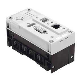
Festo CPX-E-CEC-C1-EP Parts list manual

Translation of the original instructions
CODESYS®, EtherCAT®, EtherNet/IP®, MODBUS®, WINDOWS® are registered
trademarks of the respective trademark owners in certain countries.
1 About this document
This document describes the use of the above-mentioned product.
Certain aspects of use are described in other documents and must be observed
è 1.1 Further applicable documents.
1.1 Further applicable documents
Document Contents
Description of automation system CPX-E
(CPX-E-SYS)
Detailed description of automation system
CPX-E
Instruction manual for automation system CPX-E
(CPX-E-SYS)
Instruction manual and important information
on assembly, electrical installation and main-
tenance tasks for an automation system CPX-E
Description of controller CPX-E-CEC-...-EP
(CPX-E-CEC-...-EP)
Detailed description of controller
CPX-E-CEC-...-EP
CODESYS Installation and getting started.pdf
CODESYS_OPC_Server_V3_Benutzerhandbuch.pdf
Working with CODESYS
èInstallation directory for the software
Online help for CODESYS V3 Detailed information on using the product with
CODESYS V3 and the Festo extensions
Online help for CODESYS libraries Description of the function blocks for an expan-
ded function range of the controller
Instruction manual for operator unit CDSB General functions of the operator unit
Tab. 1 Further applicable documents
All available documents for the product èwww.festo.com/pk.
1.2 Product version
This document refers to the following product versions:
Product Programming Version
CPX-E-CEC-C1-EP with CODESYS V3 Revision1 or later
CPX-E-CEC-M1-EP with CODESYS V3 and SoftMot-
ion
Revision1 or later
Tab. 2 Product version
The product version can be identified from the product labelling or with the help
of appropriate software from Festo.
Appropriate software for determining the product version can be found in the
Festo Support Portal èwww.festo.com/sp.
Information on using the software can be found in the integrated Help function.
There may be an updated version of this document for these or later product ver-
sions.
• Check whether a corresponding version of this document is available on the
Festo Support Portal èwww.festo.com/sp.
1.3 Product labelling
The product labelling is located on the left-hand side of the module. Scanning the
printed Data Matrix Code with an appropriate device opens the Festo Support
Portal, with the information appropriate for the product. Alternatively, the Product
Key (11-digit alphanumeric code on the product labelling) can be entered in the
search field of the Support Portal.
You can find detailed information on the product labelling in the description of the
module è 1.1 Further applicable documents.
1.4 Specified standards
Version status
EN60529:2013-10 IEC60204-1:2014-10
EN61000-6-2:2005-08 NE21:2012-05
EN61000-6-4:2007-01 –
Tab. 3 Standards specified in the document
2 Sicherheit
2.1 Safety instructions
– Take into consideration the legal regulations for the respective destination.
– Use the product only within the defined values è 13 Technical data.
– Observe labelling on the product.
– Observe further applicable documents.
– Store the product in a cool, dry, UV-protected and corrosion-protected envir-
onment. Ensure that storage times are kept to a minimum.
– Before working on the product: switch off the power supply and secure it
against being switched on again.
– Comply with the handling specifications for electrostatically sensitive devices.
– Activate the load voltage first when the system is properly installed, con-
figured and parameterised.
2.2 Intended use
The product described in this document is intended as an autonomous CODESYS
controller for an automation system CPX-E. Interfaces for EtherNet/IP or Mod-
busTCP are available for communication with a higher-order controller. An Ether-
CAT master interface enables connection to lower-order devices.
Use the product only as follows:
– Use only in an industrial environment. Outside of industrial environments,
e.g.in commercial and mixed-residential areas, it may be necessary to take
measures to suppress interference.
– Use only in combination with modules and components that are permissible
for the respective product variant èwww.festo.com/catalogue.
– Only use the product if it is in perfect technical condition.
– Only use the product in original status without unauthorised modifications.
Only the conversions or modifications described in this and the further applic-
able documents are permitted.
2.3 Training of qualified personnel
Installation, commissioning, maintenance and disassembly should only be con-
ducted by qualified personnel.
The qualified personnel must be familiar with installation of electrical control sys-
tems.
Experience of an EtherCAT and EtherNet/IP network and with the CODESYSV3
development kit is required in order to understand this documentation.
3 Further information
– Accessories èwww.festo.com/catalogue.
– Spare parts èwww.festo.com/spareparts.
4 Service
Contact your regional Festo contact person if you have technical questions
èwww.festo.com.
Including the following information will make it easier to process support queries:
• CODESYS project as project archive èmenu command in CODESYSV3:
[File] [Project archive] [Save/send archive...]
• Version of the programming environment èmenu command in CODESYS V3
[Help] [Information...] [Show detailed version information]
• Controller data  èCopy data properties using suitable software from Festo,
e.g.Festo Field Device Tool (FFT).
5 Produktübersicht
5.1 Function
Together with additional CPX-E modules, the product forms an automation system
CPX-E that can be commissioned using CODESYSV3.
Network connection
The product can be integrated directly into a higher-order network. Communica-
tion takes place via EtherNet/IP.
ModbusTCP and standard Ethernet (TCP/IP) are also supported.
EtherCAT Master
EtherCAT Slave devices can be connected to the product.
8071211
CPX-E-CEC-...-EP
Controller
8071211
2018-09
[8071213]
Instructions| Operating
Festo AG & Co. KG
Ruiter Straße 82
73734 Esslingen
Germany
+49 711 347-0
www.festo.com
CODESYS libraries and plug-ins
Various libraries and plug-ins for CODESYSV3 are available for the easy actuation
and visualisation of CPX-E modules.
Web server
The integrated web server provides read access to the key parameters and dia-
gnostic functions of the automation system CPX-E. The web server can be
accessed by entering the IP address in the address bar of a web browser.
Factory settings for the web server:
IP address: 192.168.0.1, subnet mask: 255.255.255.0
5.2 Configuration
5.2.1 Product design
1Cover
2Ethernet network connection
[ETH 1]
3Memory card slot [Card]
4USB interface [USB]
5EtherCAT Master network connec-
tion [EC]
6Ethernet network connection
[ETH 2]
7LED indicators
8Terminal strip for operating
voltage supply UEL/SEN [XD]
9Terminal strip interlock
10 EtherNet/IP network connection
Port 2 [XF2]
11 Linking element
12 EtherNet/IP network connection
Port 1 [XF1]
13 Rotary switch for setting the 4th
octet of the IP address for the
EtherNet/IP network connection
Fig. 1 Product design
5.2.2 Display components
1Module-specific LED indicators:
– Operation [Run] (green)
– EtherCAT connection/data
traffic [LA EC] (green)
– Ethernet connection/data traffic
[LA ETH1], [LA ETH2] (green)
2System-specific LED indicators:
– Operating voltage supply
UEL/SEN [PS] (green)
– Load voltage supply UOUT [PL]
(green)
– System error [SF] (red)
– Force mode [M] (yellow)
3Network-specific LED indicators
(EtherNet/IP):
– Module status [MS] (green, red,
orange)
– Network status [NS] (green, red,
orange)
– Connection/data traffic [XF1],
[XF2] (green)
Fig. 2 LED indicators
The module- and network-specific LED displays are described below
è 11.3 LED indicators.
The system-specific LED indicators are described in the documents for the auto-
mation system CPX-E è 1.1 Further applicable documents.
5.2.3 Control elements
5.2.3.1 Run/stop switch
The run/stop switch (DIL switch) is located under the cover.
1DIL switch (for run/stop)
2DIL switch (reserved)
Fig. 3 Run/stop switch
NOTICE!
Damage to internal electronics.
Damage to at-risk components due to electrostatic discharge.
• Ensure your body is electrostatically discharged before activating the
run/stop switch.
• Activate run/stop switch as required.
Switch status Function
Run (standard setting) A project can be started using CODESYS (run mode active).
A CODESYS boot application can be started.
Stop A project cannot be started using CODESYS.
A CODESYS boot application cannot be started.
RunèStop A project that is running will be stopped.
StopèRun A project that was stopped using the run/stop switch will be contin-
ued.
Tab. 4 Run/stop switch
5.2.3.2 Rotary switch
NOTICE!
Damage to internal electronics.
Damage to at-risk components due to electrostatic discharge.
• Ensure your body is electrostatically discharged before activating the rotary
switch.
• Activate rotary switch as required.
Rotary switch Function
The 3rotary switches are used to set the 4thoctet of the IP address
for the EtherNet/IP network connection: 192.168.1.XXX.
Possible settings
0 = use the internal configuration (factory setting)
1…254 = Permissible address range
999 = reset to factory setting
For invalid values, the internal configuration is used.
Factory setting
192.168.1.1 (DHCP active)
The DIL switches are reserved and have no function.
Tab. 5 Rotary switch
Changes to the rotary switches only take effect following a restart of the module.
5.2.3.3 Operator unit CDSB (optional)
The operator unit CDSB is available as an accessory
èwww.festo.com/catalogue.
The functions of the operator unit are described in the “Description of controller
CPX-E-CEC-...-EP” è 1.1 Further applicable documents.
5.2.4 Connecting components
5.2.4.1 Operating voltage supply
Port [XD]1) Signal
0
1
+24VDC operating voltage supply UEL/SEN
2
3
0VDC operating voltage supply UEL/SEN
1) The ports XD.0 and XD.1 and also XD.2 and XD.3, respectively, are interconnected in the terminal strip.
Tab. 6 Port [XD]
5.2.4.2 Network connections
Port [XF1], [XF2], [ETH1], [ETH2],
[EC]
Signal
1 TD+ Transmitted data +
2 TD– Transmitted data –
3 RD+ Received data +
4 n.c. –
5 n.c. –
6 RD– Received data –
7 n.c. –
8 n.c. –
1) Shield Functional earth
1) Housing
Tab. 7 Port [XF1], [XF2], [ETH1], [ETH2], [EC]
Connection Function
[XF1] EtherNet/IPPort1
[XF2] EtherNet/IPPort2
[ETH1]
[ETH2]
Ethernet interfaces for the connection of a programming device,
PC or operating unit CDPX
[EC] EtherCAT Master
Tab. 8 Network connections
The network connections ETH1 and ETH2 are connected to the controller via a
switch.
5.2.4.3 Memory card slot [Card]
The slot is used to save data and results to a memory card CAMC-M-MS-G32.
– The data are saved in the directory /mnt/sdcard.
– The data are accessed through SysFile and CAA.File èCODESYS libraries.
Requirements:
– Maximum memory size: 32GB
– Formatting: FAT32 (one partition only)
When using a memory card, please note the direction and orientation.
Use only memory cards that are sold by Festo as accessories for the product
èwww.festo.com/catalogue.
Festo does not provide any warranty for the use of other memory cards.
The memory card slot is only intended for user-monitored operation.
• Do not use memory cards for continuous data recording.
Memory cards cannot be used to execute CODESYS boot projects.
5.2.4.4 USB interface [USB]
The USB interface (A-coded socket, USB specification2.0) is used to save data
and results to external storage media.
– The data from the USB memory are saved in the directory /mnt/usb.
– The data are accessed through SysFile and CAA.File èCODESYS libraries.
Requirements:
– Maximum memory size: 32GB
– Formatting: FAT32 (one partition only)
NOTICE!
Impermissible operating states of the controller result from high current con-
sumption at the USB interface.
•Use only storage media with a current consumption of £0.5A.
The USB interface is only intended for user-monitored operation.
• Do not use storage media for continuous data recording.
USB storage devices cannot be used to execute CODESYS boot projects.
6 Transport and storage
• Observe specifications for environmental and storage conditions
è 13 Technical data.
7 Assembly
• Assemble the module as outlined in the “Instruction manual for automation
system CPX-E” è 1.1 Further applicable documents.
8 Installation
8.1 Network
NOTICE!
Unauthorised access to the device can cause damage or malfunctions.
When connecting the device to a network, protect the network from unauthorised
access.
Measures to protect the network include:
• Firewall
• Intrusion prevention system (IPS)
• Network segmentation
• Virtual LAN (VLAN)
• Virtual private network (VPN)
• Security at physical access level (port security)
Further informationèDirectives and standards for security in information tech-
nology, e.g.IEC62443, ISO/IEC27001.
Network
An access password only protects against unintentional modification.
NOTICE!
Transmission errors due to faulty installation or excessive transmission rates.
• Please note the line specifications in the documentation of the controller.
8.2 Operating voltage supply UEL/SEN
NOTICE!
Malfunction due to faulty installation.
• Please note the information regarding the line specification, power supply
and earthing measures.
1. Please note the information in the “Instruction manual for automation system
CPX-E” è 1.1 Further applicable documents.
2. Make sure that the power supply is switched off.
3. Connect the lines to the terminal strip in accordance with the “Instruction
manual for automation system CPX-E” è 1.1 Further applicable documents.
9 Commissioning
You can find information on commissioning the automation system CPX-E in the
“Instruction manual for automation system CPX-E”.
You can find information on the parameters in the “Description of
automation system CPX-E” and in the descriptions of the modules used
è 1.1 Further applicable documents.
9.1 Behaviour of the display components after error-free commissioning
[MS] (green) [NS] (green) [XF1], [XF2] (green)
Lit Lit Lit or flashing
Tab. 9 Display components after error-free commissioning
[PS] (green) [PL] (green) [SF] (red) [M] (yellow)
Lit Lit Off Off
Tab. 10 Display components after error-free commissioning
You can find information on troubleshooting in the event of incorrect behaviour in
the “Description of automation system CPX-E” and the descriptions of the mod-
ules used è 1.1 Further applicable documents.
9.2 Commissioning with CODESYS
CAUTION!
Risk of injury due to uncontrolled movements of the connected actuators.
• Perform test runs of projects and applications without active actuators first.
• For the configuration, parameterisation and programming of the product, use
CODESYSV3.
Requirements
– PC (Windows7 and later) with Ethernet interface
– Components for network connection
– Programming software CODESYSV3
– Package CPX-E-CEC compliant with firmware of product
Preparations
The user requires administrator rights to install and operate programming soft-
wareCODESYSV3.
1. Install CODESYSV3.
2. Start CODESYSV3 with administrator rights.
3. Open Package Manager èmenu command [Tools] [Package Manager].
4. Install the current package for CPX-E-CECè online help for CODESYSV3
è“Package Manager”.
5. Restart CODESYSV3 in order to use the new package.
6. Connect the controller to the network connection[ETH 1] or [ETH 2] through a
switch/hub or directly to the PC è 8.1 Network.
7. Adapt the network settings èmenu command [Online] [Scan Festo Devices]
èonline help for CODESYSV3 è“Scan Festo Devices”.
The current version of the packageCPX-E-CEC for CODESYSV3 is available in the
Festo Support Portal èwww.festo.com/sp.
Further information is available in the product-specific Help
èOnline help for CODESYSV3 è“Getting started”.
Procedure for unwanted program states
If a program with real-time priority is not responding:
1. Set run/stop switch to stop.
ÄThe boot application cannot be started.
2. Restart the controller.
3. Establish connection to CPX-E-CEC.
4. Delete boot application using “Reset device to original state”
èGeneral help for CODESYSV3.
10 Service
NOTICE!
Accumulation of heat due to reduced air supply to electronics.
• Keep the ventilation slots free and regularly remove contamination.
10.1 Firmware service (update)
• Update the controller firmware with suitable software from Festo
èwww.festo.com/sp.
11 Diagnostics and fault clearance
11.1 Diagnostics options
Various options are available for diagnosing errors:
– Internal system diagnostics
– LED indicators on the product
11.2 Internal system diagnostics
The internal system diagnostics is described in the “Description of automation
system CPX-E” è 1.1 Further applicable documents.
11.3 LED indicators
The module- and network-specific LED displays are described below.
The system-specific LED indicators are described in the documents for the auto-
mation system CPX-E è 1.1 Further applicable documents.
Module-specific LED indicators
Operation [Run]
LED
(green)
Meaning Remedy
Lit
CODESYS application is running –
Off
CODESYS application is not available or
has stopped
–
Tab. 11 Operation [Run]
Ethernet interfaces [LA ETH 1] [LA ETH 2]
LED
(green)
Meaning Remedy
Lit
Network connection established
Status “Link”
–
Flashing
Network connection established
Status “Activity”
–
Off
No network connection Check network connection.
Tab. 12 Ethernet interfaces [LA ETH 1] [LA ETH 2]
EtherCAT interface [LA EC]
LED
(green)
Meaning Remedy
Lit
Network connection established
Status “Link”
–
Flashing
Network connection established
Status “Activity”
–
Off
No network connection Check network connection.
Tab. 13 EtherCAT interface [LA EC]
Network-specific LED indicators
Connection status [XF1], [XF2]
LED
(green)
Meaning Remedy
Lit
Network connection established
Status “Link”
–
Flashing
Network connection established
Status “Activity”
–
Off
No network connection Check network connection.
Tab. 14 Connection status [XF1], [XF2]
Module status [MS]
LED
(green,
red,
orange)
Meaning Remedy
Lit up
green
Normal operating status –
Flashing
green
Configuration of automation system CPX-E
not complete or not correct
Complete or correct configuration of the
automation system CPX-E.
Lit up red
Error cannot be rectified Contact Festo Service èwww.festo.com.
Flashing
red
Error can be rectified Check configuration of the automation
system CPX-E.
Module status [MS]
LED
(green,
red,
orange)
Meaning Remedy
Flashing
altern-
ately
red/green
The automation system CPX-E is in self-
test mode.
–
Lit up
orange
Bootloader –
Off
No logic power supply to the network
interface
Check logic supply.
Tab. 15 Module status [MS]
Network status [NS]
LED
(green,
red,
orange)
Meaning Remedy
Lit up
green
The automation system CPX-E is online
and has a network connection (normal
operating status).
–
Flashing
green
The automation system CPX-E is online
and has received an IP address but does
not have a configured network connection.
Check configuration of the automation
system CPX-E; it is possible that the auto-
mation system CPX-E is not assigned to a
master/scanner.
Lit up red
Communication has failed.
Non-permitted IP address set that is
already used in the network.
Correct IP address.
Flashing
red
One or more “I/O connections” are in the
“time-out state”.
Check the physical connection to the
master/scanner.
Flashing
altern-
ately
red/green
The automation system CPX-E is in self-
test mode.
–
Lit up
orange
Bootloader, if the LED[MS] is also lit up
orange è Network-specific LED indicators
–
Off
The automation system CPX-E is offline.
No IP address assigned or no IP address
received from DHCP server.
Check network connection.
Check IP addressing settings.
Tab. 16 Network status [NS]
12 Disposal
ENVIRONMENT!
Send the packaging and product for environmentally sound recycling in accord-
ance with the current regulations èwww.festo.com/sp.
13 Technical data
General technical data
Automation system CPX-E
Description of automation system CPX-E
è 1.1 Further applicable documents
Dimensions
(Length × width × height)1)
[mm] 124.3 × 75.9 × 82.5
Product weight2) [g] 288
Mounting position Vertical/horizontal
Ambient temperature [°C] –5…+60 (–5…+50)3)
Storage temperature [°C] –20…+70
Air humidity
(non-condensing)
[%] 0…95
Degree of protection in accordance with
EN60529
IP20
Protection against electric shock
(Protection against direct and indirect
contact in accordance with IEC60204-1)
through the use of PELV circuits
(protected extra-low voltage)
Electromagnetic compatibility to EN61000-6-2/-4 and NE21
Module code/submodule code
CPX-E-CEC-C1-EP 222/102
CPX-E-CEC-M1-EP 222/103
Module identification
CPX-E-CEC-C1-EP E-CEC-C1-EP
CPX-E-CEC-M1-EP E-CEC-M1-EP
1) Including cover, not including linking element
2) Including linking element
3) for horizontal mounting position
Tab. 17 General technical data
Power supply
Operating voltage supply
UEL/SEN
[VDC] 24_25 %
Intrinsic current consumption
at nominal operating voltage
24V from UEL/SEN
[mA] typ. 150
Reverse polarity protection
24V UEL/SEN against
0V UEL/SEN
Yes
Mains buffering time [ms] 20
Tab. 18 Power supply
Network-specific data
Protocol EtherNet/IP1), EtherCAT
Transmission rate [Mbps] 10/100 (full duplex/half duplex)
Crossover detection Auto-MDI/MDI-X
Maximum cable length per
segment
[m] 1002)
Cable specification
Cable type Ethernet twisted pair cable, shielded
Transmission class Category Cat5/Cat5e (linkclass)
Cable diameter [mm] 6…8
Wire cross section [mm2] 0.14…0.75; 22AWG3)
1) based on the Ethernet protocol IEEE802.3
2) at a transmission rate of 100Mbps
3) Required for maximum connection length between network participants
Tab. 19 Network-specific data

This manual suits for next models

1

Other Festo Controllers manuals

Festo VPPM-**C1 Series User manual

Festo

Festo VPPM-**C1 Series User manual

Festo SPC200 Series User manual

Festo

Festo SPC200 Series User manual

Festo CPX-CEC-C1 User manual

Festo

Festo CPX-CEC-C1 User manual

Festo CMXR-C2 Instruction Manual

Festo

Festo CMXR-C2 Instruction Manual

Festo EXCM-2ST-C3-1 User manual

Festo

Festo EXCM-2ST-C3-1 User manual

Festo CECC-X-M1 series Parts list manual

Festo

Festo CECC-X-M1 series Parts list manual

Festo SFC-DC series User manual

Festo

Festo SFC-DC series User manual

Festo DAPS Series User manual

Festo

Festo DAPS Series User manual

Festo DFPI-ND2P Series Setup guide

Festo

Festo DFPI-ND2P Series Setup guide

Festo SFC-DC-VC-3-E-H0-CO Reference guide

Festo

Festo SFC-DC-VC-3-E-H0-CO Reference guide

Festo DMSP Series User manual

Festo

Festo DMSP Series User manual

Festo CPX-E-CEC PN User manual

Festo

Festo CPX-E-CEC PN User manual

Festo SPC-10 Series User manual

Festo

Festo SPC-10 Series User manual

Festo SEC-AC-305-CO User manual

Festo

Festo SEC-AC-305-CO User manual

Festo LF-M Series User manual

Festo

Festo LF-M Series User manual

Festo EXCM-10-***-E User manual

Festo

Festo EXCM-10-***-E User manual

Festo VPPI S1BT Series User manual

Festo

Festo VPPI S1BT Series User manual

Festo VPPI S1D Series User manual

Festo

Festo VPPI S1D Series User manual

Festo MPP-3-1/8 User manual

Festo

Festo MPP-3-1/8 User manual

Festo CECX-K-D1 User manual

Festo

Festo CECX-K-D1 User manual

Festo DGSL E Series User manual

Festo

Festo DGSL E Series User manual

Festo CPX-CEC Series User manual

Festo

Festo CPX-CEC Series User manual

Festo CP-FB11-E Owner's manual

Festo

Festo CP-FB11-E Owner's manual

Festo SFC-LAC-IO Series Reference guide

Festo

Festo SFC-LAC-IO Series Reference guide

Popular Controllers manuals by other brands

Chino LT830 Series instructions

Chino

Chino LT830 Series instructions

SEW-Eurodrive MOVI-C UHX65A-M manual

SEW-Eurodrive

SEW-Eurodrive MOVI-C UHX65A-M manual

Omron E5CC-T instruction manual

Omron

Omron E5CC-T instruction manual

hager coviva Smartbox TKP100A Configuration guide

hager

hager coviva Smartbox TKP100A Configuration guide

Idegis D-10+ Operation manual

Idegis

Idegis D-10+ Operation manual

SilverCloud 500VA user manual

SilverCloud

SilverCloud 500VA user manual

IBM 3708 End-User Reference

IBM

IBM 3708 End-User Reference

Allied NeXGen Installation and startup guide

Allied

Allied NeXGen Installation and startup guide

Teledyne THCD-101 instruction manual

Teledyne

Teledyne THCD-101 instruction manual

GFA 51171735 00002 Guide

GFA

GFA 51171735 00002 Guide

Edwards 4-NET-TP-HC Installation sheet

Edwards

Edwards 4-NET-TP-HC Installation sheet

Smarteh LPC-2.NE1 user manual

Smarteh

Smarteh LPC-2.NE1 user manual

ZyXEL Communications NXC2500 troubleshooting guide

ZyXEL Communications

ZyXEL Communications NXC2500 troubleshooting guide

Brainchild C21 user manual

Brainchild

Brainchild C21 user manual

Danfoss AMEi 6 iSET operating guide

Danfoss

Danfoss AMEi 6 iSET operating guide

Spirax Sarco LCR2250 Installation and maintenance instructions

Spirax Sarco

Spirax Sarco LCR2250 Installation and maintenance instructions

Woodward DTSC-200 installation manual

Woodward

Woodward DTSC-200 installation manual

Prozeda primos 600 SR Installation and operating instructions

Prozeda

Prozeda primos 600 SR Installation and operating instructions

manuals.online logo
manuals.online logoBrands
  • About & Mission
  • Contact us
  • Privacy Policy
  • Terms and Conditions

Copyright 2025 Manuals.Online. All Rights Reserved.