ASEA AC112Q-3 User manual

Operations Manual
for the ASEA Power Systems
Model AC112Q-3, AC125Q-3, AC150Q-3, and AC165Q-3
3 Phase Yacht Power Converter
619050
Revision B
Issued 6/27/2017

AC112Q-3, AC125Q-3, AC150Q-3, and AC165Q-3 Operations Manual.... 2
CERTIFICATION
ASEA Power Systems certifies that this product was thoroughly tested and inspected and found to meet or
exceed its published specifications when shipped from the factory.
WARRANTY
ASEA Power Systems warrants each unit to be free from defects in material and workmanship. For a period
of 18 months after purchase or 12 months after installation (whichever is shorter), ASEA Power Systems
will repair or replace any defective module provided the unit has been installed and operated in a manner
according to this manual. A thorough inventory of spare parts & modules is maintained at our factory. Our
world-wide sales/support facilities also inventory a complement of spare parts and modules.
ASEA Power Systems is not responsible for consequential damage arising from the use of its equipment.
It does not apply to extensively modified or non-standard systems. Debit memos for returned units are not
accepted, and will cause return of the system without repair.
LIFE SUPPORT POLICY
ASEA Power Systems does not authorize the use of any of its products or systems for use an AC voltage
supply (source) for life support systems. Life support systems are devices which support or sustain life, and
whose failureto perform, when properly used in accordance with this OperationsManual, can bereasonably
expected to result in significant injury to the user.

AC112Q-3, AC125Q-3, AC150Q-3, and AC165Q-3 Operations Manual.... 3
1 USING THIS MANUAL
This manual has been written as an Operations Manual. Installation, Operations, and Preventative
Maintenance are covered in detail. This manual will cover the following model:
AC112Q-3 112kVA 3 Phase Yacht Power Converter
AC125Q-3 125kVA 3 Phase Yacht Power Converter
AC150Q-3 150kVA 3 Phase Yacht Power Converter
AC165Q-3 165kVA 3 Phase Yacht Power Converter
Please note that these converters are capable of being paralleled for higher power applications.
The Model AC112Q-3 can be paralleled to produce the following models:
AC225Q-3/2 225kVA 3 Phase Yacht Power Converter
The Model AC125Q-3 can be paralleled to produce the following models:
AC250Q-3/2 250kVA 3 Phase Yacht Power Converter
AC375Q-3/3 375kVA 3 Phase Yacht Power Converter
AC500Q-3/4 500kVA 3 Phase Yacht Power Converter
The Model AC150Q-3 can be paralleled to produce the following models:
AC300Q-3/2 300kVA 3 Phase Yacht Power Converter
AC450Q-3/3 450kVA 3 Phase Yacht Power Converter
AC600Q-3/4 600kVA 3 Phase Yacht Power Converter
AC750Q-3/5 750kVA 3 Phase Yacht Power Converter
AC900Q-3/6 900kVA 3 Phase Yacht Power Converter
The Model AC165Q-3 can be paralleled to produce the following models:
AC330Q-3/2 330kVA 3 Phase Yacht Power Converter
AC500Q-3/3 500kVA 3 Phase Yacht Power Converter
AC660Q-3/4 660kVA 3 Phase Yacht Power Converter
AC825Q-3/5 825kVA 3 Phase Yacht Power Converter
AC990Q-3/6 990kVA 3 Phase Yacht Power Converter
It is important that the operator reads this manual prior to installing and operating the converter.
A thorough understanding of the information covered in this manual is required for proper
installation and operation.
If any questions arise while reading this manual, the user is encouraged to call ASEA Power
Systems. ASEA Power Systems is located at:

AC112Q-3, AC125Q-3, AC150Q-3, and AC165Q-3 Operations Manual.... 4
ASEA Power Systems
15272 Newsboy Circle
Huntington Beach, CA. 92649
Phone (714) 896-9695
FAX (714) 896-9679
Web http://www.aseapower.com

AC112Q-3, AC125Q-3, AC150Q-3, and AC165Q-3 Operations Manual.... 5
TABLE OF CONTENTS
CERTIFICATION .......................................................................................................................... 2
WARRANTY ................................................................................................................................. 2
1USING THIS MANUAL.................................................................................................... 3
2SAFETY NOTICES............................................................................................................ 7
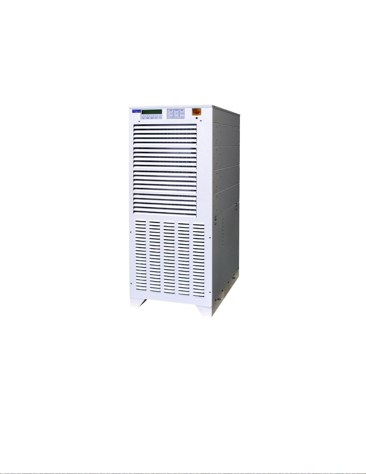
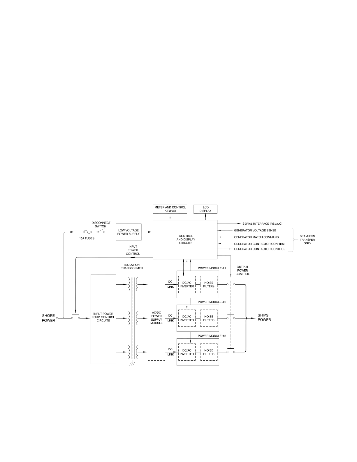
3 INTRODUCTION TO THE CONVERTERS........................................................................ 9
4SPECIFICATIONS........................................................................................................... 11
4.1 ELECTRICAL SPECIFICATIONS ..................................................................... 11
4.1.1 Input Service............................................................................................. 11
4.1.2 Output Service .......................................................................................... 12
4.2 PHYSICAL SPECIFICATIONS .......................................................................... 14
4.2.1 Mechanical................................................................................................ 14
4.2.2 Environmental........................................................................................... 14
5INSTALLATION ............................................................................................................. 15
5.1 MECHANICAL INSTALLATION...................................................................... 16
5.2 ELECTRICAL INSTALLATION........................................................................ 19
5.2.1 Input Power Connections.......................................................................... 20
5.2.2 Output Power Connections....................................................................... 20
5.2.3 Grounding................................................................................................. 22
5.2.4 Multi-Cabinet Connections....................................................................... 23
5.2.5 Seamless Transfer Connections................................................................ 24
5.2.6 Other Optional Connections ..................................................................... 25
6OPERATION.................................................................................................................... 26
6.1 POWER TURN-ON PROCEDURE..................................................................... 26
6.1.1 Systems Not Equipped with The Seamless Transfer Option.................... 28
6.1.2 Systems Equipped with The Seamless Transfer Option........................... 29
6.2 MULTI-CABINET OPERATION........................................................................ 31
6.3 AUTO-RESTART FEATURE ............................................................................. 32
6.3.1 Operation................................................................................................... 33
6.4 TURN-OFF PROCEDURE.................................................................................. 34
6.4.1 Systems Not Equipped with The Seamless Transfer Option.................... 34
6.4.2 Systems Equipped with The Seamless Transfer Option........................... 35
6.5 REMOTE COMMUNICATIONS........................................................................ 36
6.5.1 RS-232C/SCPI.......................................................................................... 37
6.5.2 RS-485/Modbus........................................................................................ 38
7SOFTWARE FEATURES................................................................................................ 41
7.1 GENERAL............................................................................................................ 41
7.2 LOAD MANAGEMENT...................................................................................... 41
7.3 LOAD MANAGEMENT OPERATION.............................................................. 43
7.3.1 Shore Cord Alarm, Single, Master, and Slave converters ........................ 43
7.3.2 Shore Cord Setup, Single, Master, or Slave Converters........................... 44
7.3.3 Voltage Droop, Single or Master Converters ........................................... 45

AC112Q-3, AC125Q-3, AC150Q-3, and AC165Q-3 Operations Manual.... 6
7.3.4 Automatic Transfer to Generator, Single or Master Converters (Seamless
Transfer installed)..................................................................................... 46
7.3.5 Quick Setup of Shore Cord Alarm, Single, Master, or Slave Converters. 47
7.4 GENERATOR FREQUENCY ANALYSIS ........................................................ 48
7.5 CONVERTER OUTPUT IMPEDANCE CONTROL.......................................... 48
7.6 AGC CONTROL.................................................................................................. 49
7.7 kW-HOUR METER AND MAXIMUM POWER LEVEL DISPLAY................ 49
7.8 CONVERTER OUTPUT VOLTAGE CONTROL.............................................. 50
7.9 EVENT LOG........................................................................................................ 50
8TROUBLE-SHOOTING AND DIAGNOSTICS............................................................. 53
8.1 COMMON PROBLEMS...................................................................................... 53
8.2 FAILURE AND WARNING MESSAGES.......................................................... 54
8.3 INFO DISPLAY ................................................................................................... 54
8.4 STATUS WORDS................................................................................................ 54
8.5 GATHERING DATA........................................................................................... 55
8.6 SOFTWARE TOOLS........................................................................................... 55
8.7 POWER MODULE SWITCH.............................................................................. 56
8.8 POWER MODULE FUSES ................................................................................. 57
10 MAINTENANCE............................................................................................................. 61
11 INTERNATIONAL POWER FORM REFERENCE....................................................... 62
13. INDEX.................................................................................................................................... 69
TABLE OF FIGURES
Figure 1: SYSTEM BLOCK DIAGRAM....................................................................................... 9
Figure 2: MECHANICAL OUTLINE.......................................................................................... 17
Figure 3: MECHANICAL OUTLINE.......................................................................................... 18
Figure 4: INPUT AND OUTPUT CONNECTIONS.................................................................... 21
Figure 5: FRONT PANEL CONTROLS...................................................................................... 26
Figure 6: RS-232C PINOUT ........................................................................................................ 37
Figure 7: RS-485 CONNECTIONS.............................................................................................. 38
Figure 8: STATUS WORD BIT DEFINITIONS ......................................................................... 56
Figure 9: POWER MODULE SIWTCH & LED.......................................................................... 57
Figure 10: POWER MODULE FUSES........................................................................................ 57
TABLE OF TABLES
Table 1: Input Power Specifications............................................................................................. 11
Table 2: Output Power Specifications .......................................................................................... 12
Table 3: Output Rated Current Specifications vs. Voltages......................................................... 13
Table 4: Mechanical Specifications.............................................................................................. 14
Table 5: Environmental Specifications......................................................................................... 14
Table 6: Installation Clearance Specifications.............................................................................. 16
Table 7: Maximum Input Current under Low-Line Conditions ................................................... 19

AC112Q-3, AC125Q-3, AC150Q-3, and AC165Q-3 Operations Manual.... 7
2 SAFETY NOTICES
Each shore power converter is capable of transferring large amounts of electrical energy very
quickly. This quality is fundamental to a high performance power converter. International symbols
are used throughout this manual to stress important information. Read the text below each symbol
carefully and use professional skills and prudent care when performing the actions described by
the text.
THE CAUTION SYMBOL (TRIANGLE ENCLOSING AN EXCLAMATION POINT)
INDICATES A CONDITION THAT COULD SERIOUSLY DAMAGE EQUIPMENT AND
POSSIBLY INJURE PERSONNEL. CAUTIONS WILL BE PRESENTED IN THIS FORM.
ALL CAUTIONS SHOULD BE RIGOROUSLY OBSERVED.
THE WARNING SYMBOL (TRIANGLE WITH A LIGHTNING BOLT) IS USED TO
SIGNAL THE PRESENCE OF A POSSIBLE SERIOUS, LIFE THREATENING
CONDITION. A CONDITION THAT IS HAZARDOUS TO BOTH PERSONNEL AND
EQUIPMENT WILL BE ISSUED AS A WARNING. ALL WARNINGS WILL BE
PRESENTED IN THIS FORM.

AC112Q-3, AC125Q-3, AC150Q-3, and AC165Q-3 Operations Manual.... 8
•THIS EQUIPMENT CONTAINS HIGH ENERGY, LOW IMPEDANCE
CIRCUITS! LETHAL POTENTIALS ARE CONTAINED WITHIN THE
SYSTEM EVEN WHEN IT APPEARS NON-OPERATIONAL.
•CARE MUST BE EXERCISED WHEN SERVICING THIS EQUIPMENT IN
ORDER TO PREVENT SERIOUS OPERATOR INJURY OR EQUIPMENT
DAMAGE.
•DO NOT WORK ON OR OPERATE THIS EQUIPMENT UNLESS YOU ARE
FULLY QUALIFIED TO DO SO. NEVER WORK ALONE.
•THE EQUIPMENT IS NOT IGNITION RATED; IT MUST NOT BE OPERATED
IN AREAS WHERE COMBUSTIBLE GASES MAY ACCUMULATE.
•DO NOT REMOVE THE SHORE CORD FROM THE DOCK PEDESTAL
WITHOUT FIRST OPENING THE DOCK OR YACHT BREAKER. FAILURE
TO DO SO MAY RESULT IN DAMAGE TO THE CONVERTER AND
PEDESTAL.
•OBSERVE THE FOLLOWING WHEN SERVICE AND MAINTENANCE ARE
REQUIRED:
•REMOVE ALL JEWELRY FROM ARMS AND NECK WHEN SERVICING THIS
EQUIPMENT. THIS PREVENTS THE POSSIBILITY OF SHORTING
THROUGH THE JEWELRY, OR ELECTROCUTION OF THE OPERATOR.
•WEAR SAFETY GLASSES WHEN SERVICING THIS EQUIPMENT TO
PREVENT EYE INJURY DUE TO FLYING PARTICLES CAUSED BY
ACCIDENTAL SHORT CIRCUIT CONDITIONS.
•DO NOT REMOVE ANY PANELS OR COVERS WITHOUT FIRST OPENING
ALL SHORE POWER AND SWITCHGEAR CIRCUIT BREAKERS
DISTRIBUTING POWER TO AND FROM THE CONVERTER, AND THEN
REMOVING THE INPUT SERVICE.
•SERVICE SHOULD BE REFERRED TO PERSONNEL AUTHORIZED BY THE
FACTORY TO SERVICE THIS EQUIPMENT.

AC112Q-3, AC125Q-3, AC150Q-3, and AC165Q-3 Operations Manual.... 9
3 INTRODUCTION TO THE CONVERTERS
The AC112Q-3, AC125Q-3, AC150Q-3, and AC165Q-3 are high performance Yacht Power
Converters utilizing dual-conversion technology. The systems will accept any three phase input
service with a frequency between 40-70Hertz, and a voltage between 330-520VAC.
The output power form has been programmed at the factory for the voltage and frequency required
by your yacht.
Dual-conversion technology is the preferred technique for AC power conversion, and was chosen
for the system. In this technology, the shore power service is isolated by the transformer, then
converted to DC power by the phase multiplier power supplies. The output inverters then convert
the DC power back to the required AC form (both voltage and frequency) required by the yacht.
Figure 1: SYSTEM BLOCK DIAGRAM

AC112Q-3, AC125Q-3, AC150Q-3, and AC165Q-3 Operations Manual.... 10
Being a converter designed from the ground up specifically for the yachting industry, all efforts
have been made to produce a system capable of withstanding the marine environment. The system
is constructed using a modular approach where the converter consists of a control module (upper),
three (AC112Q-3 and AC125Q-3) or four (AC150Q-3 and AC165Q-3) power modules (middle),
and a transformer module (bottom). This allows the converter to be broken down into five/six parts
to facilitate its movement into a vessel through existing personnel entry points. All system
components are packaged in drip-proof, dust-resistant, aluminum (control and power modules)
and stainless steel (bottom) chassis. Major components are internally modular, allowing a simple
exchange in the unlikely event of failure. Maintenance and service are performed through top
access to the upper control module, exchange of power modules, and front/top access to the
transformer module.
Fan speed control is provided. Internal cooling fans will run at full rpm when the converter is at
full load, and minimal speed while unloaded.
System operation is managed through three basic operators:
A safety disconnect on the front of the enclosure is used for securing input service during periods
of disuse, when maintenance and/or service is in-process, or when an emergency shutdown is
needed. Three membrane switch groups in the control console—SHORE POWER, CONVERTER
POWER, and SHIP’S POWER—provide normal operation of the system. Each switch group
contains an ON and OFF switch with associated LED indicators.
Each power module has an ON/OFF switch for disconnecting the power module from the converter
when non-operational—the converter may be operated with one or two power modules in-service.
In addition to the basic function of power conversion, each converter provides the user with a
sophisticated power analysis and monitoring capacity. All parameters for input and output power,
along with operations and status information, are available on the front panel display console.
Various displays are selected through a long life, sealed membrane switch panel.
For additional information on controls and indicators, please refer to Section 6.

AC112Q-3, AC125Q-3, AC150Q-3, and AC165Q-3 Operations Manual.... 11
4 SPECIFICATIONS
4.1 ELECTRICAL SPECIFICATIONS
4.1.1 Input Service
Table 1: Input Power Specifications
Parameter
AC112Q-3
AC125Q-3
AC150Q-3
AC165Q-3
AC225Q-3/2
AC250Q-3/2
AC300Q-3/2
AC330Q-3/2
AC375Q-3/3
Input Power Form
Three Phase
Input Voltage Range (L-L)
330-520Vrms
Input Frequency Range
40-70 Hertz
Input Current, Max. Three
Phase
170Arms
190Arms
230Arms
250Arms
340Arms
380Arms
460Arms
500Arms
570Arms
Input Current, Soft Start,
Max.
80Arms
80 Arms
80 Arms
80 Arms
160Arms
160Arms
160Arms
160Arms
240Arms
Input Current Distortion
<8% THD
Input Power Factor
>0.98 @ rated load
Parameter
AC450Q-3/3
AC495Q-3/3
AC500Q-3/4
AC600Q-3/4
AC660Q-3/4
AC750Q-3/5
AC825Q-3/5
AC900Q-3/6
AC990Q-3/6
Input Power Form
Three Phase
Input Voltage Range (L-L)
330-520Vrms
Input Frequency Range
40-70 Hertz
Input Current, Max. Three
Phase
460Arms
725Arms
760Arms
920Arms
1000Arms
1150Arms
1250Arms
1380Arms
1500Arms
Input Current, Soft Start,
Max.
240Arms
240Arms
320Arms
320Arms
320Arms
400Arms
400Arms
480Arms
480Arms
Input Current Distortion @
rated load
<8% THD
Input Power Factor
>0.98 @ rated load

AC112Q-3, AC125Q-3, AC150Q-3, and AC165Q-3 Operations Manual.... 12
4.1.2 Output Service
Table 2: Output Power Specifications
Parameter
AC112Q-3
AC125Q-3
AC150Q-3
AC165Q-3
AC225Q-3/2
AC250Q-3/2
AC300Q-3/2
AC330Q-3/2
AC375Q-3/3
Output Power Rating (kVA)
@ 0.85
112
125
150
165
225
250
300
330
375
Output Power Form
Three-Phase 220/380 VAC, 230/400 VAC, 240/416 VAC, 254/440 VAC, and 277/480VAC
Output Frequency (Hz)
50 or 60 Hertz
Output Frequency Accuracy
0.01%
Output Voltage Distortion
< 1.5% THD
Output Voltage Line
Regulation
0.50%
Output Voltage Load
Regulation
1.00%
Output Voltage Response
Time
0.20 msec.
Output Current, Continuous
Refer to Table 1 on the following page for basic ratings.
Output Current, Peak
250% of cont. rating
Output Current, Surge
165% of cont. rating
Conversion Efficiency
93% @ rated load
Parameter
AC450Q-3/3
AC495Q-3/3
AC500Q-3/4
AC600Q-3/4
AC660Q-3/4
AC750Q-3/5
AC825Q-3/5
AC900Q-3/6
AC990Q-3/6
Output Power Rating (kVA)
@ 0.85
450
495
500
600
660
750
825
900
990
Output Power Form
Three-Phase 220/380 VAC, 230/400 VAC, 240/416 VAC, 254/440 VAC, and 277/480VAC
Output Frequency (Hz)
50 or 60 Hertz
Output Frequency Accuracy
0.01%
Output Voltage Distortion
< 1.5% THD
Output Voltage Line
Regulation
0.50%
Output Voltage Load
Regulation
1.00%
Output Voltage Response
Time
0.20 msec.
Output Current, Continuous
Refer to Table 1 on the following page for basic ratings.
Output Current, Peak
250% of cont. rating
Output Current, Surge
165% of cont. rating
Conversion Efficiency
93% @ rated load

AC112Q-3, AC125Q-3, AC150Q-3, and AC165Q-3 Operations Manual.... 13
4 SPECIFICATIONS, cont.
4.1 ELECTRICAL SPECIFICATIONS,cont.
4.1.2 Output Service, cont.
Table 3: Output Rated Current Specifications vs. Voltages
Output Form
AC112Q-3
ARMS/Ø
AC125Q-3
ARMS/Ø
AC150Q-3
ARMS/Ø
AC165Q-3
ARMS/Ø
AC225Q-3/2
ARMS/Ø
AC250Q-3/2
ARMS/Ø
AC300Q-3/2
ARMS/Ø
AC330Q-3/2
ARMS/Ø
AC375Q-3/3
ARMS/Ø
3Ø, 277/480VRMS
139
154
185
204
278
309
370
407
463
3Ø, 254/440VRMS
148
164
197
217
295
328
394
433
492
3Ø, 240/416VRMS
156
174
208
229
313
347
417
458
521
3Ø, 230/400VRMS
163
181
217
239
326
362
435
478
543
3Ø, 220/380VRMS
170
189
227
250
341
379
455
500
568
Output Form
AC450Q-3/3
ARMS/Ø
AC495Q-3/3
ARMS/Ø
AC500Q-3/4
ARMS/Ø
AC600Q-3/4
ARMS/Ø
AC660Q-3/4
ARMS/Ø
AC750Q-3/5
ARMS/Ø
AC825Q-3/5
ARMS/Ø
AC900Q-3/6
ARMS/Ø
AC990Q-3/6
ARMS/Ø
3Ø, 277/480VRMS
556
611
617
741
815
926
1019
1111
1222
3Ø, 254/440VRMS
591
650
656
787
866
984
1083
1181
1299
3Ø, 240/416VRMS
625
688
694
833
917
1042
1146
1250
1375
3Ø, 230/400VRMS
652
717
725
870
957
1087
1196
1304
1435
3Ø, 220/380VRMS
682
750
758
909
1000
1136
1250
1364
1500

AC112Q-3, AC125Q-3, AC150Q-3, and AC165Q-3 Operations Manual.... 14
4 SPECIFICATIONS, cont.
4.1 ELECTRICAL SPECIFICATIONS, cont.
4.1.3 Control, Metering, and Status
Input Power Control Input Service Disconnect Switch, 2 pos.
Shore Power Control Membrane Switch, Input ON/OFF Control
Converter Power Control Membrane Switch, Output ON/OFF Control,
Ship’s Power Control Generator/Shore Power Transfer Control
Shore Power Metering Voltage, Current, Frequency, kVA, kW, %Load
Converter Power Metering Voltage, Current, Frequency, kVA, kW, %Load
Generator Power Metering Generator 1 - 4 Voltage, Frequency
System Status Operational status, Diagnostics, Software Calibration
Event Log Diagnostics
4.2 PHYSICAL SPECIFICATIONS
4.2.1 Mechanical
Table 4: Mechanical Specifications
Parameter
AC112Q-3/AC125Q-3
AC150Q-3/AC165Q-3
Height
55.2"/140cm
62.2"/158cm
Width, Enclosure
23.2"/58.9cm
23.2"/58.9cm
Depth
35.3"/89.6cm
35.3"/89.6cm
Weight
1,980lbs/898kg
2,080lbs/943kg
4.2.2 Environmental
Table 5: Environmental Specifications
Parameter
AC112Q-3/AC125Q-3
AC150Q-3/AC165Q-3
Ambient Temperature Range
0-50C non-condensing
Air Exchange Rate
1,800CFM
2,000CFM

AC112Q-3, AC125Q-3, AC150Q-3, and AC165Q-3 Operations Manual.... 15
5 INSTALLATION
The installation section is divided into two parts. The first will cover mechanical installation, the
second, electrical installation.
Read this manual thoroughly prior to attempting the installation. Improper installation is the most
significant cause of system start-up problems and service issues over the product’s life. Upon
receipt of the equipment, perform an external visual inspection. Verify that nameplate information
is consistent with the ship’s power requirements (required form, voltage, and frequency).
Proper planning will speed up installation, location, and connection of the equipment. Follow the
suggested minimum clearances provided in Table 2.
Ensure the room/compartment has adequate ventilation and cooling. The thermal load
presented by the converter will be substantial, approximately 27,000BTU/Hr at maximum
continuous load for the AC112Q-3 & AC125Q-3. The thermal load presented by the
converter will be substantial, approximately 32,750BTU/Hr at maximum continuous load
for the AC150Q-3. The thermal load presented by the converter will be substantial,
approximately 36,000BTU/Hr at maximum continuous load for the AC165Q-3.
THE CONVERTERS ARE HEAVY, WEIGHING 2,080lbs. (943kg) EXTREME CAUTION
MUST BE EXERCISED IN HANDLING AND INSTALLATION TO AVOID
EQUIPMENT DAMAGE OR INJURY TO PERSONNEL. AN ADEQUATE MATERIAL
HANDLING DEVICE SHOULD BE USED FOR UNLOADING, MOVING, AND
POSITIONING THE SYSTEM.

AC112Q-3, AC125Q-3, AC150Q-3, and AC165Q-3 Operations Manual.... 16
5.1 MECHANICAL INSTALLATION
The converters were designed for deck mount installations and as such are provided with eight
mounting holes. Mounting holes have been provided with 0.56” (14.2mm) diameters; ½” (13mm)
stainless steel hardware is required.
The mounting surface should be flat and dimensionally stable to within 1/16” (1.5mm) to prevent
torsional stresses being applied to the structure of the converter. Spacers (shim stock) may be
added between the mounting surface and the converter mounting flanges to adjust the mounting
plane. If the system is to be mounted in a high vibration/shock environment, then the factory must
be consulted concerning the application. Drawings for approved shock mounting assemblies will
be supplied.
The following recommended clearances must be considered during installation for proper
operation:
Table 6: Installation Clearance Specifications
FOR PROPER
Operation
Service
Front
24” (Exhaust Airflow)
24” min
Sides
0”
6”
Top
0”
6”
Rear
5” (Intake Airflow)
0”
Air intake grillwork is provided at the rear of the equipment. Please contact factory engineers for
review of the installation plan if unsure on any specification or requirement.

AC112Q-3, AC125Q-3, AC150Q-3, and AC165Q-3 Operations Manual.... 17
5.1 MECHANICAL INSTALLATION, cont.
Figure 2: MECHANICAL OUTLINE FOR AC150Q-3 & AC165Q-3

AC112Q-3, AC125Q-3, AC150Q-3, and AC165Q-3 Operations Manual.... 18
5.1 MECHANICAL INSTALLATION, cont.
Figure 3: MECHANICAL OUTLINE

AC112Q-3, AC125Q-3, AC150Q-3, and AC165Q-3 Operations Manual.... 19
5.2 ELECTRICAL INSTALLATION
This procedure assumes the physical installation of the converter has been completed.
It is the installer’s responsibility to provide input service over-current protection and disconnect
means.
It is recommended that connection be made to the distribution bus through a manually operated
disconnect device such as a molded case switch or circuit breaker (rated for the total system
amperage) to ease disconnection and provide a safe servicing environment in the event of converter
failure.
Follow the table below when considering shore power input cabling.
Table 7: Maximum Input Current under Low-Line Conditions
Model
AC112Q-3
AC125Q-3
AC150Q-3
AC165Q-3
Input Current @
330Vrms (L-L)
180 Arms
200 Arms
240 Arms
264 Arms
MAXIMUM OUTPUT CURRENTS: Refer to Table 1
All power wiring requires the removal of the front panel and the cable access cover (cabinet
bottom). Drill or punch appropriate holes for the selected strain reliefs. Re-install the front panel
using the removed hardware. Place the disconnect switch in the OFF position.

AC112Q-3, AC125Q-3, AC150Q-3, and AC165Q-3 Operations Manual.... 20
5.2 ELECTRICAL INSTALLATION, cont.
INPUT WIRING MUST BE PERFORMED BY A QUALIFIED ELECTRICIAN
FAMILIAR WITH STANDARD SAFEGUARDS AND PROCEDURES REQUIRED BY
THE INSTALLATION OF THIS TYPE OF EQUIPMENT. POWER MUST BE
REMOVED FROM THE INPUT DISTRIBUTION SYSTEMS SUPPLYING POWER TO
THE AC112Q-3, AC125Q-3, AC150Q-3 & AC165Q-3 PRIOR TO THE START OF THE
FOLLOWING STEPS. INPUT POWER MUST BE SECURED (LOCKED) IN THE OFF
(DE-ENERGIZED) STATE UNTIL INSTRUCTED OTHERWISE BYTHIS DOCUMENT.
ALSO SECURE IN THE OFF STATE ANY CIRCUIT BREAKER(S) IN THE
SWITCHGEAR PANEL THAT MAY BE SUPPLYING SHIP’S BUS POWER TO THE
CONVERTER OUTPUT TERMINAL BLOCK. FAILURE TO FOLLOW THESE
PROCEDURES CAN RESULT IN DAMAGE TO THE EQUIPMENT, AND CAN
PRESENT THE RISK OF INJURY OR DEATH TO THE INSTALLER OR THE
OPERATOR.
5.2.1 Input Power Connections
The converter is supplied with 3/8” stud type terminal blocks for input power connections (SHORE
POWER). These terminal blocks accept wires at a 3/8” stud. Refer to the applicable standards for
selection of required wire gauge and type. In two or more cabinet systems, one shore cord is
connected to each converter shore power terminal block.
5.2.2 Output Power Connections
Each system is supplied with 3/8” stud type terminal blocks for output power connections
(CONVERTER POWER). These terminal blocks accept wires at a 3/8” stud. The chassis ground
is formed by a separate 3/8” stud in-between the input and output terminal blocks. Refer to the
applicable standard for selection of the required wire gauge and type. Please refer to Figure 4 on
the following page for additional detail.
This manual suits for next models
3
Table of contents
Other ASEA Media Converter manuals
Popular Media Converter manuals by other brands

Texas Instruments
Texas Instruments TL5001EVM-097 user guide

AJA
AJA Hi5-3G Installation and operation guide

National Instruments
National Instruments NI 6221 user manual

Sony
Sony NSBK-A16H installation manual

PR
PR 9116 Series product manual

Data Conversion Systems
Data Conversion Systems dCS Puccini U-Clock user manual