ASEA AC50Q-3 User manual

Operations Manual
for the ASEA Power Systems
Model AC50Q-3, AC63Q-3,
And AC75Q-3
3 Phase Yacht Power Converters
P/N 630050,
Revision A
Issued 7/19/2013

AC50Q-3 / AC63Q-3 / AC75Q-3 Operations Manual....2
CERTIFICATION
ASEA Power Systems certifies that this product was thoroughly tested and inspected and found to meet or
exceed its published specifications when shipped from the factory.
WARRANTY
ASEA Power Systems warrants each unit to be free fromdefects inmaterialand workmanship. For aperiodof
18 months after purchase or 12 months after installation (whichever is shorter), ASEA Power Systems will
repair or replace any defective module provided the unit has been installed and operatedinamanner according
to this manual. A thorough inventoryof spare parts & modules is maintained at our factory. Our world-wide
sales/support facilities also inventory a complement of spare parts and modules.
ASEA Power Systems is not responsible for consequential damage arising from the use of its equipment. It
does not apply to extensively modified or non-standard systems. Debit memos for returned units are not
accepted, and will cause return of the system without repair.
LIFE SUPPORT POLICY
ASEA Power Systems does not authorize the use of any of its products or systems for use an AC voltage
supply (source) for life support systems. Life support systems are devices which support or sustain life, and
whose failure to perform, when properly used in accordance with this Operations Manual, can be reasonably
expected to result in significant injury to the user.

AC50Q-3 / AC63Q-3 / AC75Q-3 Operations Manual....3
1 USING THIS MANUAL
This manual has been written as an Operations Manual. Installation, Operations, and Preventative
Maintenance are covered in detail. This manual will cover the following models:
AC50Q-3 50kVA 3 Phase Yacht Power Converter
AC63Q-3 63kVA 3 Phase Yacht Power Converter
AC75Q-3 75kVA 3 Phase Yacht Power Converter
Please note that each converter is capable of being paralleled for higher power applications.
The Model AC50Q-3 can be paralleled to produce the following models:
AC100Q-3/2 100kVA 3 Phase Yacht Power Converter
AC150Q-3/3 150kVA 3 Phase Yacht Power Converter
AC200Q-3/4 200kVA 3 Phase Yacht Power Converter
The Model AC63Q-3 can be paralleled to produce the following models:
AC125Q-3/2 125kVA 3 Phase Yacht Power Converter
AC190Q-3/3 190kVA 3 Phase Yacht Power Converter
AC250Q-3/4 250kVA 3 Phase Yacht Power Converter
The Model AC75Q-3 can be paralleled to produce the following models:
AC150Q-3/2 150kVA 3 Phase Yacht Power Converter
AC225Q-3/3 225kVA 3 Phase Yacht Power Converter
AC300Q-3/4 300kVA 3 Phase Yacht Power Converter
It is important that the operator reads this manual prior to installing and operating the converter. A
thorough understandingof the information covered in this manual is required forproper installation
and operation. If anyquestions arise while readingthis manual, the user is encouragedtocall ASEA
Power Systems. ASEA Power Systems is located at:
ASEA Power Systems
15602 Commerce Lane
Huntington Beach, CA. 92649
Phone (714) 896-9695
FAX (714) 896-9679
http://www.aseapower.com

AC50Q-3 / AC63Q-3 / AC75Q-3 Operations Manual....4
TABLE OF CONTENTS
CERTIFICATION............................................................................................................................2
WARRANTY ..................................................................................................................................2
1 USING THIS MANUAL.....................................................................................................3
2 SAFETY NOTICES.............................................................................................................6
3 INTRODUCTION TO THE CONVERTERS.....................................................................8
4 SPECIFICATIONS............................................................................................................10
4.1 ELECTRICAL SPECIFICATIONS.......................................................................10
4.1.1 Input Service..............................................................................................10
4.1.2 Output Service ...........................................................................................10
4.1.3 Control, Metering, and Status....................................................................12
4.2 PHYSICAL SPECIFICATIONS............................................................................12
4.2.1 Mechanical ............................................................................................12
4.2.2 Environmental............................................................................................12
5 INSTALLATION...............................................................................................................13
5.1 MECHANICAL INSTALLATION .......................................................................14
5.2 ELECTRICAL INSTALLATION..........................................................................17
5.2.1 Input Power Connections...........................................................................18
5.2.2 Output Power Connections........................................................................18
5.2.3 Grounding..................................................................................................20
5.2.4 Multi-Cabinet Connections........................................................................21
5.2.5 Seamless Transfer Connections.................................................................22
5.2.6 Other Optional Connections ......................................................................23
6 OPERATION.....................................................................................................................24
6.1 POWER TURN-ON PROCEDURE......................................................................24
6.1.1 Systems Not Equipped With The Seamless Transfer Option....................26
6.1.2 Systems Equipped With The Seamless Transfer Option...........................27
6.2 MULTI-CABINET TURN-ON PROCEDURE.....................................................29
6.3 AUTO-RESTART FEATURE ..............................................................................30
6.3.1 Operation....................................................................................................31
6.4 TURN-OFF PROCEDURE ...................................................................................32
6.4.1 Systems Not Equipped With The Seamless Transfer Option....................32
6.4.2 Systems Equipped With The Seamless Transfer Option...........................33
6.5 REMOTE COMMUNICATION ...........................................................................34
6.5.1 RS-232C/SCPI...........................................................................................35
6.5.2 RS-485/Modbus.........................................................................................36

AC50Q-3 / AC63Q-3 / AC75Q-3 Operations Manual....5
7 SOFTWARE FEATURES.................................................................................................39
7.1 GENERAL.............................................................................................................39
7.2 LOAD MANAGEMENT.......................................................................................39
7.3 LOAD MANAGEMENT OPERATION...............................................................41
7.3.1 Shore Cord Alarm, Single, Master, and Slave converters .........................41
7.3.2 Shore Cord Setup, Single, Master, or Slave Converters............................42
7.3.3 Voltage Droop, Single or Master Converters.............................................43
7.3.4 Automatic Transfer to Generator, Single or Master Converters (Seamless
Transfer installed)......................................................................................44
7.3.5 Quick Setup of Shore Cord Alarm, Single, Master, or Slave Converters..45
7.4 GENERATOR FREQUENCY ANALYSIS..........................................................46
7.5 CONVERTER OUTPUT IMPEDANCE CONTROL...........................................46
7.6 AGC CONTROL...................................................................................................47
7.7 kW-HOUR METER AND MAXIMUM POWER LEVEL DISPLAY.................48
7.8 CONVERTER OUTPUT VOLTAGE CONTROL...............................................49
7.9 EVENT LOG .........................................................................................................50
8 TROUBLE-SHOOTING AND DIAGNOSTICS ..............................................................52
8.1 COMMON PROBLEMS.......................................................................................52
8.2 FAILURE AND WARNING MESSAGES...........................................................53
8.3 INFO DISPLAY.....................................................................................................53
8.4 STATUS WORDS.................................................................................................54
8.5 GATHERING DATA............................................................................................54
8.6 SOFTWARE TOOLS............................................................................................54
8.7 POWER MODULE SWITCH...............................................................................56
8.8 POWER MODULE FUSES ..................................................................................56
9 CALIBRATION.................................................................................................................57
10 MAINTENANCE ..............................................................................................................59
11 INTERNATIONAL POWER FORM REFERENCE........................................................60
12 INDEX...............................................................................................................................67
FIGURES
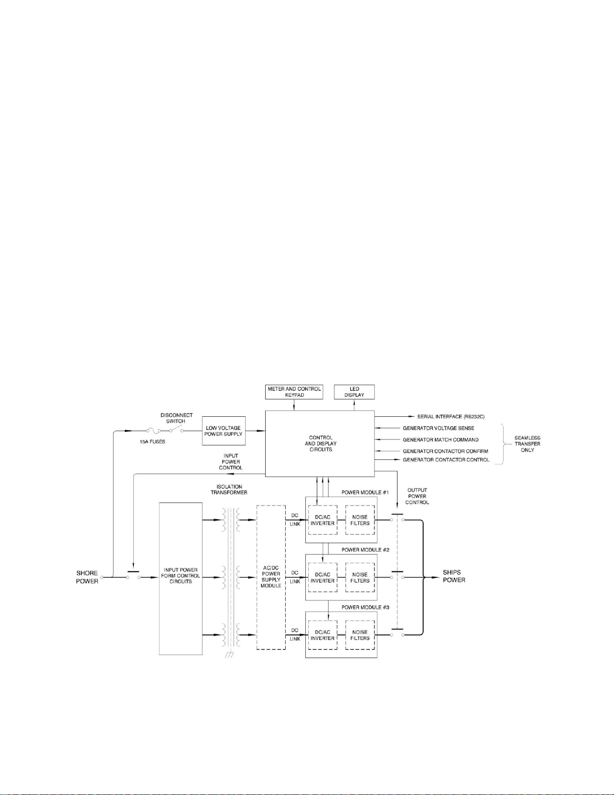
1 SYSTEM BLOCK DIAGRAM ...........................................................................................8
2 MECHANICAL OUTLINE...............................................................................................15
3 MECHANICAL OUTLINE...............................................................................................16
4 INPUT AND OUTPUT CONNECTIONS ........................................................................19
5 FRONT PANEL CONTROLS...........................................................................................24
6 RS-232C PINOUT.............................................................................................................35
7 RS-485 CONNECTIONS..................................................................................................36
8 STATUS WORD BIT DEFINITIONS ..............................................................................55
9 POWER MODULE SWITCH AND LED.........................................................................56
10 POWER MODULE FUSES ..............................................................................................56

AC50Q-3 / AC63Q-3 / AC75Q-3 Operations Manual....6
2 SAFETY NOTICES
Each shore power converter is capable of transferring large amounts of electrical energy very
quickly. This quality is fundamental to a high performance powerconverter. International symbols
are used throughout this manual to stress important information. Read the text below each symbol
carefullyand use professional skills and prudent care when performing the actions described bythe
text.
THE CAUTION SYMBOL (TRIANGLE ENCLOSING AN EXCLAMATION POINT)
INDICATES A CONDITION THAT COULD SERIOUSLY DAMAGE EQUIPMENT AND
POSSIBLY INJURE PERSONNEL. CAUTIONS WILL BE PRESENTED IN THIS FORM.
ALL CAUTIONS SHOULD BE RIGOROUSLY OBSERVED.
THE WARNING SYMBOL (TRIANGLE WITH A LIGHTNING BOLT) IS USED TO
SIGNAL THE PRESENCE OF A POSSIBLE SERIOUS, LIFE THREATENING
CONDITION. A CONDITION THAT IS HAZARDOUS TO BOTH PERSONNEL AND
EQUIPMENT WILL BE ISSUED AS A WARNING. ALL WARNINGS WILL BE
PRESENTED IN THIS FORM.

AC50Q-3 / AC63Q-3 / AC75Q-3 Operations Manual....7
THIS EQUIPMENT CONTAINS HIGH ENERGY, LOWIMPEDANCE CIRCUITS!
LETHAL POTENTIALSARECONTAINED WITHINTHESYSTEMEVENWHEN
IT APPEARS NON-OPERATIONAL.
CAREMUSTBEEXERCISEDWHENSERVICINGTHISEQUIPMENTINORDER
TO PREVENT SERIOUS OPERATOR INJURY OR EQUIPMENT DAMAGE.
DO NOT WORK ON OR OPERATE THIS EQUIPMENT UNLESS YOU ARE
FULLY QUALIFIED TO DO SO. NEVER WORK ALONE.
THE EQUIPMENT IS NOT IGNITIONRATED; ITMUSTNOTBE OPERATEDIN
AREAS WHERE COMBUSTIBLE GASES MAY ACCUMULATE.
DO NOT REMOVE THE SHORE CORD FROM THE DOCK PEDESTAL
WITHOUT FIRST OPENING THE DOCK OR YACHT BREAKER. FAILURE TO
DO SO MAY RESULT IN DAMAGE TO THE CONVERTER AND PEDESTAL.
OBSERVE THE FOLLOWING WHEN SERVICE AND MAINTENANCE ARE
REQUIRED:
REMOVE ALL JEWELRY FROM ARMS AND NECK WHEN SERVICING THIS
EQUIPMENT. THIS PREVENTS THE POSSIBILITY OF SHORTINGTHROUGH
THE JEWELRY, OR ELECTROCUTION OF THE OPERATOR.
WEARSAFETYGLASSESWHENSERVICINGTHISEQUIPMENTTOPREVENT
EYE INJURY DUE TO FLYINGPARTICLES CAUSEDBYACCIDENTAL SHORT
CIRCUIT CONDITIONS.
DO NOT REMOVE ANYPANELS ORCOVERSWITHOUTFIRSTOPENINGALL
SHORE POWER AND SWITCHGEAR CIRCUIT BREAKERS DISTRIBUTING
POWER TO AND FROM THE CONVERTER, AND THEN REMOVING THE
INPUT SERVICE.
SERVICE SHOULD BE REFERRED TO PERSONNEL AUTHORIZED BY THE
FACTORY TO SERVICE THIS EQUIPMENT.

AC50Q-3 / AC63Q-3 / AC75Q-3 Operations Manual....8
3 INTRODUCTION TO THE CONVERTERS
Each model is a high performance Yacht Power Converter utilizing dual-conversion technology.
The systems will accept any three phase input service with a frequency between 40-70Hertz, and a
voltage between 170-520VAC.
The output power form has been programmed at the factory for the voltage and frequency required
by your yacht.
Dual-conversion technologyis the preferred techniqueforACpowerconversion,and waschosen for
each system. In this technology, the shore power service is isolated by the transformer, then
converted to DC power by the phase multiplier power supplies. The output inverters then convert
the DC power back to the required AC form (both voltage and frequency) required by the yacht.
FIGURE 1 SYSTEM BLOCK DIAGRAM

AC50Q-3 / AC63Q-3 / AC75Q-3 Operations Manual....9
3 INTRODUCTION TO THE CONVERTERS, cont.
Being a converter designed from the ground up specificallyfor the yachtingindustry,alleffortshave
been made to produce a system capable of withstanding the marine environment. The system is
constructed using a modular approach where the converter consists of a control module (upper),
three power modules (middle) (two for the AC50Q-3), and a transformer module (bottom). This
allows the converter to be broken down into five parts to facilitate its movement into a vessel
through existing personnel entry points. All system components are packaged in drip-proof, dust-
resistant, aluminum chassis. Major components are internally modular, allowingasimpleexchange
in the unlikely event of failure. Maintenance and service are performed through top access to the
upper control module, exchange of power modules, and front/top access to the transformer module.
Fan speed control is provided. Internal cooling fans will run at full rpm when the converter is at full
load, and minimal speed while unloaded.
System operation is managed through three basic operators:
A safetydisconnect on the front of the enclosure is used for securinginput service duringperiods of
disuse, when maintenance and/or service is in-process, or when an emergencyshutdown is needed.
Three membrane switch groups in the control console—SHOREPOWER,CONVERTERPOWER,
and SHIP’S POWER—provide normal operation of the system. Each switch group contains an ON
and OFF switch with associated LED indicators.
Each power module has an ON/OFF switch for disconnecting the power module from the converter
when non-operational—the converter may be operated with one or two power modules in-service.
In addition to the basic function of power conversion, each converter provides the user with a
sophisticated power analysis and monitoring capacity. All parameters for input and output power,
along with operations and status information, are available on the front panel display console.
Various displays are selected through a long life, sealed membrane switch panel.
For additional information on controls and indicators, please refer to Section 6.

AC50Q-3 / AC63Q-3 / AC75Q-3 Operations Manual....10
4 SPECIFICATIONS
4.1 ELECTRICAL SPECIFICATIONS
Parameter AC50Q-3 AC63Q-3 AC75Q-3
4.1.1 Input Service
Input Power Form Three Phase Three Phase Three Phase
Input Voltage Range 170-520VAC 170-520VAC 170-520VAC
Input Frequency Range 40-70 Hertz 40-70 Hertz 40-70 Hertz
Input Current, Max. Three Phase 147 ARMS 186 ARMS 220 ARMS
Input Current, Soft Start, Max. 42 ARMS42 ARMS42 ARMS
Input Current Distortion <8% THD @ rated load <8% THD @ rated load <8% THD @ rated load
Input Power Factor >0.98 @ rated load >0.98 @ rated load >0.98 @ rated load
4.1.2 Output Service
Output Power Rating 50kVA @ 0.85 p.f. 63kVA @ 0.85 p.f. 75kVA @ 0.85 p.f.
Output Power Form Three-Phase 120/208VAC, 127/220VAC, 220/380 VAC,230/400 VAC, 240/416 VAC,
254/440 VAC,and 277/480VAC
Output Frequency 50 or 60 Hertz 50 or 60 Hertz 50 or 60 Hertz
Output Frequency Accuracy 0.01% 0.01% 0.01%
Output Voltage Distortion < 1.5% THD < 1.5% THD < 1.5% THD
Output Voltage Line Regulation 0.50% 0.50% 0.50%
Output Voltage Load Regulation 1.0% 1.0% 1.0%
Output Voltage Response Time 0.20 msec. 0.20 msec. 0.20 msec.
Output Current, Continuous Refer to Table 1 on the following page for basic ratings.
Output Current, Peak 300% of cont. rating 360% of cont. rating 300% of cont. rating
Output Current, Surge (ARMS) 215% of cont. rating 255% of cont. rating 215% of cont. rating
Conversion Efficiency 93% @ rated load 93% @ rated load 93% @ rated load

AC50Q-3 / AC63Q-3 / AC75Q-3 Operations Manual....11
4.1 ELECTRICAL SPECIFICATIONS,cont.
4.1.2 Output Service, cont.
Table 1 - Output Current, Rated Continuous RMS
Output Form
AC50Q-3
AC63Q-3
AC75Q-3
3Ø, 277/480VRMS
60ARMS/Ø
76ARMS/Ø
90ARMS/Ø
3Ø, 254/440VRMS
66ARMS/Ø
83ARMS/Ø
98ARMS/Ø
3Ø, 240/416VRMS
69ARMS/Ø
88ARMS/Ø
104ARMS/Ø
3Ø, 230/400VRMS
72ARMS/Ø
91ARMS/Ø
109ARMS/Ø
3Ø, 220/380VRMS
76ARMS/Ø
95ARMS/Ø
114ARMS/Ø
3Ø, 127/220VRMS
131ARMS/Ø
165ARMS/Ø
197ARMS/Ø
3Ø, 120/208VRMS
139ARMS/Ø
175ARMS/Ø
209ARMS/Ø

AC50Q-3 / AC63Q-3 / AC75Q-3 Operations Manual....12
4.1 ELECTRICAL SPECIFICATIONS, cont.
4.1.3 Control, Metering, and Status
Input Power Control Input Service Disconnect Switch, 2 pos.
Shore Power Control Membrane Switch, Input ON/OFF Control
Ship’s Power Control Membrane Switch, Output ON/OFF Control,
Converter Power Control Generator/Shore Power Transfer Control
Shore Power Metering Voltage, Current, Frequency, kVA, kW, %Load
Converter Power Metering Voltage, Current, Frequency, kVA, kW, %Load
Generator Power Metering Generator 1 & 2 Voltage, Frequency
System Status Operational status, Diagnostics, Software Calibration
4.2 PHYSICAL SPECIFICATIONS
Parameter AC50Q-3 AC63Q-3 AC75Q-3
4.2.1 Mechanical
Height 37.3"/94.7cm 42.5"/108cm 42.5"/108cm
Width, Enclosure 19.2"/48.8cm 19.2"/48.8cm 19.2"/48.8cm
Depth 25.3"/64.3cm 25.3"/64.3cm 25.3"/64.3cm
Weight 840lbs/382kg * 950lbs/431kg 950lbs/431kg
* Upgradeable version.
4.2.2 Environmental
Ambient Temperature Range 0-50C non-condensing 0-50C non-condensing 0-45C non-condensing
Air Exchange Rate 1,200CFM 1,200CFM 1,200CFM

AC50Q-3 / AC63Q-3 / AC75Q-3 Operations Manual....13
5 INSTALLATION
This installation section is divided into two parts: the first section covers mechanical installation
while the second covers electrical installation.
Read this manual thoroughly prior to attempting the installation. Improper installation is the most
significant cause of system start-up problems and service issues over the product’s life. Upon receipt
of the equipment, perform an external visual inspection. Verify that nameplate information is
consistent with the ship’s power requirements (required form, voltage, and frequency).
Proper planning will speed up installation, location, and connection of the equipment. Follow the
suggested minimum clearances providedin Table2. Ensuretheroom/compartmenthasadequate
ventilation and cooling. The thermal load presented by the converter will be substantial and
approximately 10,915 BTU/Hr atmaximumcontinuousload fortheAC50Q-3;13,725BTU/Hr
for the AC63Q-3; and 16,320 BTU/Hr for the AC75Q-3.
THE CONVERTER IS HEAVY, WEIGHING UP TO 950lbs. (431kg)
DEPENDING ON THE OPTIONS INSTALLED. EXTREME CAUTION
MUST BE EXERCISED IN HANDLING AND INSTALLATION TO AVOID
EQUIPMENT DAMAGE OR INJURY TO PERSONNEL. AN ADEQUATE
MATERIAL HANDLING DEVICE SHOULD BE USED FOR UNLOADING,
MOVING, AND POSITIONING THE SYSTEM.

AC50Q-3 / AC63Q-3 / AC75Q-3 Operations Manual....14
5.1 MECHANICAL INSTALLATION
The converters were designed for deck mount installations and as such are provided with six
mounting holes, three per side. Mounting holes have been provided with ½” (12.7mm) diameters;
stainless steel hardware in the range of 3/8” to 7/16” (10-11mm) diameter is required.
The mounting surface should be flat and dimensionally stable to within 1/16” (1.5mm) to prevent
torsional stresses being applied to the structure of the converter. Spacers (shim stock) maybeadded
between the mounting surface and the converter mounting flanges to adjust the mounting plane. If
the system is to be mounted in a high vibration/shock environment, then the factory must be
consulted concerning the application. Drawings for approved shock mounting assemblies will be
supplied.
The following recommended clearances must be considered duringinstallationfor properoperation:
TABLE 2
FOR PROPER:
Operation Service
Front 12”(User access) 24” min
Lower Front Sides * 0”8”
Top 0” 14”
Rear 5” (Intake Airflow) 8”
* Side access plates exist that allow service of the Fan Power Supply and HVDC Fuses.
Air intake grillwork is provided at the rear of the equipment. A total intake area of 300 in2must be
provided through a combination of surfaces, excluding that area provided by the bottom. Please
contact factory engineers for review of the installation plan if unsure on any specification or
requirement.

AC50Q-3 / AC63Q-3 / AC75Q-3 Operations Manual....15
5.1 MECHANICAL INSTALLATION, cont.
FIGURE 2 MECHANICAL OUTLINE

AC50Q-3 / AC63Q-3 / AC75Q-3 Operations Manual....16
5.1 MECHANICAL INSTALLATION, cont.
FIGURE 3 MECHANICAL OUTLINE

AC50Q-3 / AC63Q-3 / AC75Q-3 Operations Manual....17
5.2 ELECTRICAL INSTALLATION
This procedure assumes the physical installation of the converter has been completed.
It is the installer’s responsibility to provide input service over-current protection and a
disconnect means.
It is recommended that connection be made to the distribution bus through a manually
operated disconnect devicesuch as a molded case switch or circuit breaker(rated forthetotal
system amperage) to ease disconnection and provide a safe servicing environment in the
event of converter failure.
Follow the table below when considering shore power input cabling.
MAXIMUM INPUT CURRENTS UNDER LOW-LINE CONDITIONS:
Model AC50Q-3 AC63Q-3 AC75Q-3
Input Current
Three Phase, 170-290V 180A 200A 230A
Three Phase, 330-520V 90A 105A 125A
MAXIMUM OUTPUT CURRENTS: Refer to Table 1, page 11
All power wiring requires the removal of the front panel and the cable access cover (cabinet
bottom). Drill or punch appropriate holes for the selected strain reliefs. Re-install the front
panel using the removed hardware. Place the disconnect switch in the OFF position.

AC50Q-3 / AC63Q-3 / AC75Q-3 Operations Manual....18
5.2 ELECTRICAL INSTALLATION, cont.
INPUT WIRING MUST BE PERFORMED BY A QUALIFIED ELECTRICIAN
FAMILIAR WITH STANDARD SAFEGUARDS AND PROCEDURES REQUIRED
BY THE INSTALLATION OF THIS TYPE OF EQUIPMENT. POWER MUST BE
REMOVED FROMTHE INPUT DISTRIBUTIONSYSTEMSSUPPLYINGPOWER
TO THE AC50Q/AC63Q/AC75Q-3 PRIORTO THE START OFTHEFOLLOWING
STEPS. INPUT POWER MUST BE SECURED (LOCKED) IN THE OFF (DE-
ENERGIZED)STATEUNTILINSTRUCTEDOTHERWISEBYTHISDOCUMENT.
ALSO SECURE IN THE OFF STATE ANY CIRCUIT BREAKER(S) IN THE
SWITCHGEAR PANEL THAT MAY BE SUPPLYING SHIP’S BUS POWER TO
THE CONVERTER OUTPUT TERMINAL BLOCK. FAILURE TO FOLLOW
THESE PROCEDURES CAN RESULT IN DAMAGE TO THE EQUIPMENT, AND
CAN PRESENT THE RISK OF INJURY OR DEATH TO THE INSTALLER OR
THE OPERATOR.
5.2.1 Input Power Connections
The converter is supplied with compression type terminal blocksforinputpowerconnections
(SHORE POWER). These terminal blocks accept wires in therange of 4AWGto3/0AWG.
Refer to the applicable class standard for selection of required wire gauge and type. In two
or more cabinet systems, one shore cord is connected to each convertershorepower terminal
block.
5.2.2 Output Power Connections
Each system is supplied with compressiontype terminalblocksforoutputpowerconnections
(CONVERTER POWER). These terminal blocks accept wires in the range of 4 AWGto3/0
AWG. Refer to the applicable class standard for selection of the required wire gauge and
type. Please refer to Figure 4 on the following page for additional detail.

AC50Q-3 / AC63Q-3 / AC75Q-3 Operations Manual....19
5.2 ELECTRICAL INSTALLATION, cont.
FIGURE 4 INPUT AND OUTPUT CONNECTIONS
Prepare the power cables by removing approximately6”of the outer cable insulation (in the case of
SO type portable cables). Strip the insulation back exposing 1”of the bare conductor for all input,
output, and grounding conductors. Insert the prepared cables and strain relief assemblies into the
prepared holes in the cable access cover. Insert the wire ends into the appropriate input/output
terminal block and tighten. If ferrules are not used on all cables, apply sufficient wire insulation
wrap to ensure isolation between adjacent conductors. Replace the power cable access cover and
front panel using the removed hardware.

AC50Q-3 / AC63Q-3 / AC75Q-3 Operations Manual....20
5.2 ELECTRICAL INSTALLATION, cont.
5.2.3 Grounding
The converter chassis ground MUST be connected to the ship’s hull or common groundpointviathe
compression fitting terminal adjacent to the output power connections. Failure to do so maycreate
conditions that may in turn cause injury or death to operators; failure to do so will also result in the
voiding of the equipment warranty. In the case of paralleled converter systems, and where such
ground connections are not local anddirectlyadjacenttotheparalleledconverters,the chassisground
connections must be interconnected between the paralleled converters as well as connected to the
remote ship’s common ground point.
THE CONVERTER ISOLATES THE OUTPUT POWER FROM THE INPUT POWER
AND EQUIPMENT (SAFETY) GROUNDS SIMILAR TO AN ISOLATION
TRANSFORMER. THE INSTALLER MUST RE-ESTABLISH THE GROUND
REFERENCE FOR THE EQUIPMENT AT TIME OF INSTALLATION. NEUTRAL AND
EQUIPMENT (SAFETY) GROUNDS TO BE CONNECTED PER THE APPROPRIATE
CLASS STANDARD.
This manual suits for next models
2
Table of contents
Other ASEA Media Converter manuals