asecos ION-CHARGE-90 User manual

EN
USER MANUAL
Safety storage cabinets for storage
and charging of lithium ion batteries
10 YEARS WARRANTY
Upon conclusion of an asecos service and maintenance agreement (PREMIUM
tari), you will get a warranty extension for up to 10 years for your ION-LINE safety
storage cabinet.
EP.V.32907.04 | 09/2022

2
EN
IO90.195.060.K9.WDC IO90.195.060.L8.WDC IO90.078.059.057.U9.S
IO90.195.120.K3.WDC
ION-CHARGE-90
ION-CHARGE PRO-90

3
EN
Contact
Company
Street
Name of contact person
email
Serial numbers of safety storage cabinets
Phone No.
Postal code Town
YOUR PERSONAL DOCUMENTATION TO THE asecos
SAFETY CABINET
Dear Customer,
you have made a decisive investment in safety for your company by purchasing this asecos safety
storage cabinet. You now own an innovative product made of top-quality materials guaranteeing
the highest quality standards.
asecos safety storage cabinets have complete authorisation documents. We archive the authori-
sation documents for every individual cabinet, keeping them ready for you should you ever need
them (e.g. for a works inspection or similar). Simply request them using this form.
Tear of or copy that page and return to us by fax with your address and serial number of the
cabinet on it.
Yours sincerely
asecos GmbH
asecos GmbH
Customer service
Weiher feldsiedlung 16–18
D-63584 Gründau
Fax: +49 60 51 - 92 20-10
email: service asecos.com

4
EN
1. NOTES • GUIDELINES • GUARANTEE ............................................. 5
1.1. General safety notes ............................................ 5
1.2. Guarantee ..................................................... 5
1.3. Cabinet Details ................................................. 5
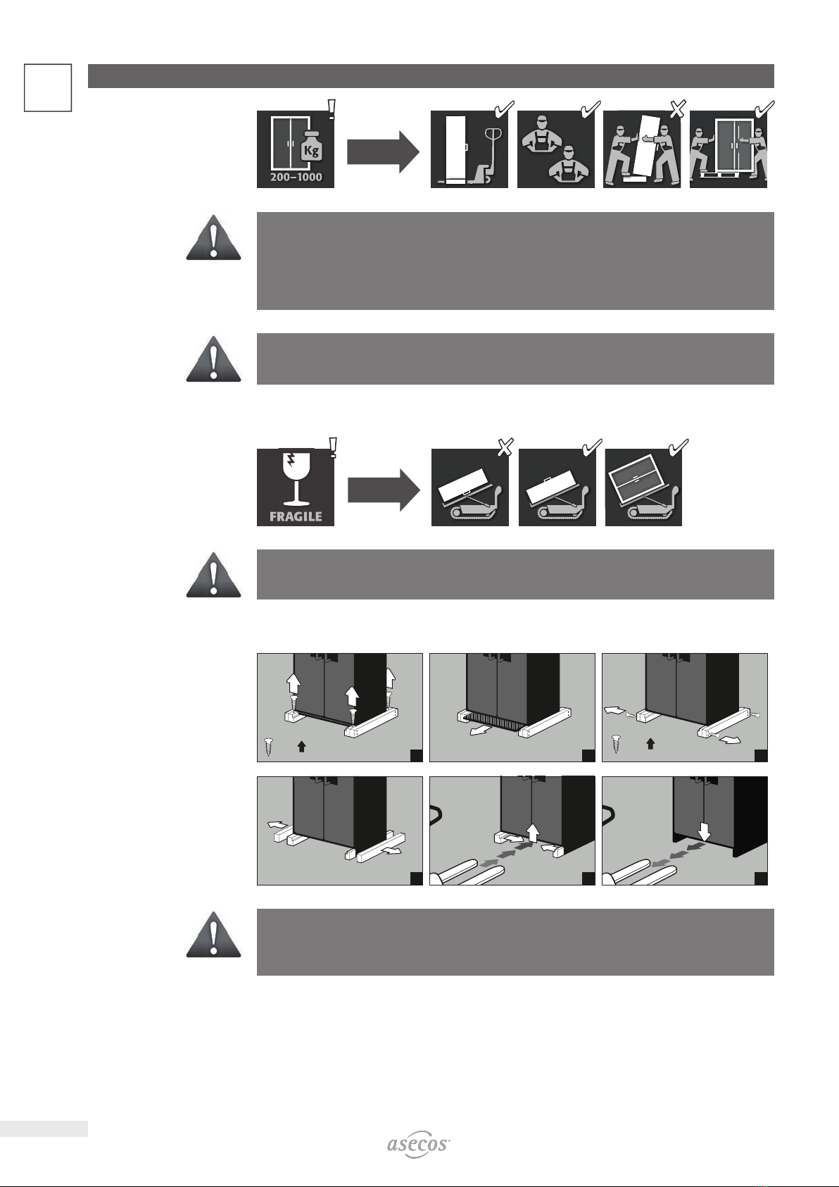
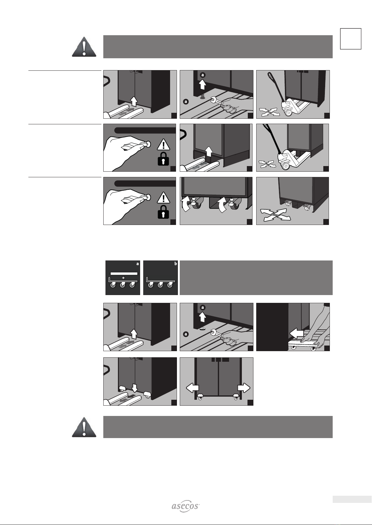
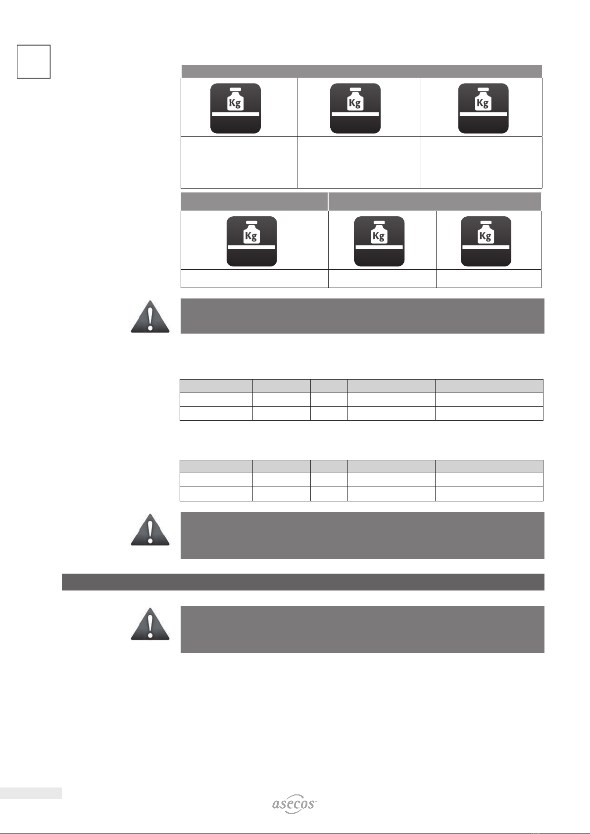
2. TRANSPORT ................................................................. 6
2.1. Tilting the cabinet .............................................. 6
2.2. Dismantling of the transport packaging ............................. 6
2.3. In-plant transport ............................................... 6
2.4. Q-Mover ...................................................... 7
2.5. Titling onto the side wall ......................................... 7
3. INSTALLATION ............................................................... 8
3.1. Alignment Of The Cabinets ....................................... 8
3.2. Commissioning ................................................. 8
4. CLOSING .................................................................... 8
4.1. In general ..................................................... 8
4.2. Locker System .................................................. 9
5. INTERIOR FITTINGS ........................................................... 9
5.1. Bottom collecting sump .......................................... 9
5.2. Storage levels with power socket strips ............................ 10
5.3. Total power rating of the power socket strips ....................... 10
6. STORAGE .................................................................. 10
6.1. Notes on storage and charging ................................... 10
7. VENTILATION ................................................................11
7.1. Extraction unit (IO90.195.120.K3.WDC) .............................11
7.2. Fan (IO90.078.059.057.U9.S) .....................................11
8. BATTERY FIRE • EVENT OF FIRE • DISPOSAL .......................................11
8.1. Fire inside the cabinet (battery fire) ............................... 12
8.2. Opening the cabinet after the fire. . . . . . . . . . . . . . . . . . . . . . . . . . . . . . . . . 13
8.3. Disposal ..................................................... 13
9. SAFETY CHECKS ............................................................. 14
9.1. All Models .................................................... 14
9.2. IO90.195.120.K3.WDC .......................................... 14
9.3. IO90.195.060.K9.WDC - IO90.078.059.057.U9.S ..................... 14
9.4. IO90.195.060.L8.WDC .......................................... 14
9.5. Contact ...................................................... 14
10. TECHNICAL DATA ............................................................ 15
11. TECHNICAL DRAWING ........................................................ 15
12. IO90.195.120.K3.WDC ........................................................ 16
12.1. Installation of the extraction unit ................................. 16
12.2. Connection to the power supply .................................. 16
12.3. Self-Test ...................................................... 17
12.4. Error during self-test ........................................... 17
12.5. Error and alarm overview. . . . . . . . . . . . . . . . . . . . . . . . . . . . . . . . . . . . . . . . 18
12.6. Potential-free alarm contact ..................................... 18
12.7. Warning/fire suppression system ................................. 19
12.8. Warning message .............................................. 19
12.9. Alarm stage 1 ................................................. 19
12.10. Alarm stage 2 ................................................. 20
13. IO90.195.060.K9.WDC ........................................................22
13.1. Connection to the power supply ..................................22
13.2. Error and alarm overview. . . . . . . . . . . . . . . . . . . . . . . . . . . . . . . . . . . . . . . . 22
13.3. Potential-free alarm contact .....................................22
13.4. False alarm of the smoke detector ................................ 23
13.5. Smoke detector - battery change ................................. 23
13.6. Smoke detector - maintenance ...................................23
14. IO90.195.060.L8.WDC ........................................................ 24
14.1. Connection to the power supply .................................. 24
14.2. Error and alarm overview. . . . . . . . . . . . . . . . . . . . . . . . . . . . . . . . . . . . . . . . 24
14.3. Potential-free alarm contact ..................................... 25
15. IO90.078.059.057.U9.S ....................................................... 26
15.1. Connection to the power supply .................................. 26
15.2. Error and alarm overview. . . . . . . . . . . . . . . . . . . . . . . . . . . . . . . . . . . . . . . . 26
15.3. Potential-free alarm contact ..................................... 26
15.4. False alarm of the smoke detector ................................ 27
15.5. Smoke detector - battery change ................................. 27
15.6. Smoke detector - maintenance ................................... 27

5
EN
1. NOTES • GUIDELINES • GUARANTEE
1.1. GENERAL SAFETY NOTES
• When handling lithium-ion batteries, observe the applicable regulations and the information in these operating
instructions
• Work on the electrical system is to be carried out only with the power turned o and only byqualified electri-
cians – refer here to the regulations of the local electricity supply company.
• General damage to electronic components is to be repaired without delay by an asecos employee.
• Use only intact and undamaged mains cables for the battery charger
• Electrical protection in accordance with local standards must be provided by the customer (cabinets do not
have their own RCD circuit breaker or circuit breaker)
• The on-site installation conditions are to be observed.
• The instructions of the supervisory engineering department must be followed.
• Observe accident prevention regulations and workplace ordinance
•Ensure that the necessary safety checks are only carried out by authorised sta using original
spare parts
• Only use the cabinet after having been properly instructed; access is to be forbidden to unauthorised persons.
• The pivoting area of the doors is to be kept free at all times; doors are to be kept closed
• By assigning trained/authorised technical personnel you can prevent the malfunctions, damage and corrosion
damage that result from inappropriate transport.
• Observe the upper limits for stored quantities, loading etc.
• The following substances may not be stored in the cabinets with a fire suppression system: acids, alkalis,
magnesium, other metals (in powder form)
Set-up requirements
0–35 °C 30–70 %
1.2. GUARANTEE
The guarantee for this product is agreed between you (the customer) and your dealer (the seller). As the
manufacturer, asecos guarantees the products listed in the operating instructions for a period of 24 months
from the date of delivery. All model safety equipment are subject to a compulsory annual inspection by spe-
cialised sta authorised by the manufacturer. Otherwise the customer’s guarantee claim against the manufac-
turer expires.
1.3. CABINET DETAILS
Cabinet data: Logbook (included with the cabinet)
Technical drawing: Appenidix 1
Technical data: Table in Appendix 2
Model Lithium ion batteries
Storing Charging Extraction air system Fire supression unit Alarm system
BATTERY CHARGE
IO90.195.060.K9.WDC 4 4 4
IO90.078.059.057.U9.S 4 4 4 4
IO90.195.060.L8.WDC 4 4 4
BATTERY CHARGE PRO
IO90.195.120.K3.WDC 4 4 4 4 4
BATTERY CHARGE PRO & BATTERY CHARGE
This model is for the active storage (charging) of lithium-ion batteries.
With active storage, lithium-ion batteries or battery packs in the cabinet are charged or partially discharged
using a charger (60—70%).

6
EN 2. TRANSPORT
CAUTION:
Transport the cabinet in an upright position on a pallet truck, tied and secured against slipping, until the
fi nal place of installation is reached.The transport locks in the door joints may only be removed directly
at the place of installation! Inappropriate transport can lead to concealed damage to the fi re protection
insulation!We can only guarantee the necessary quality if the cabinet is transported to the place of its use
by our specially trained sta .
ATTENTION:
The doors must be locked prior to transport! The extraction unit is inside the cabinet and is only mounted
after the in-plant transport to the place of use.
2.1. TILTING THE CABINET
CAUTION:
Tilting the cabinet may only be done without jolts!
2.2. DISMANTLING OF THE TRANSPORT PACKAGING
1
= 4×
2
= 8×
3
456
CAUTION:
Cabinets with a width of 600 mm: The clear entry width of the base is 520 mm.
Please note this when choosing your pallet truck!Devices with widths greater than the entry widths must
not be used.
2.3. INPLANT TRANSPORT
• In-plant transport is also possible without transport locks (inserted as standard in the door joints)

7
EN
ATTENTION:
The doors must be locked prior to transport! The extraction unit is inside the cabinet and is only mounted
after the in-plant transport to the place of use.
IO90.195.120.K3.WDC
IO90.195.060.K9.WDC
IO90.195.060.L8.WDC
12
=4×
3
IO90.078.059.057.U9.S
1
2
3
IO90.078.059.057.U9.S
plinth with castors
1
2
3
2.4. Q M O V E R
• Order no. 30037, available from your authorised dealer
a: upright transport
b: upright transport through standard doors (headroom 1986 ± 2mm)
12
=4×
3
45
CAUTION:
Written notifi cation of any damage to the cabinet must be given immediatly!
2.5. TITLING ONTO THE SIDE WALL
• Titling onto the side wall is only possible with the optionally available tilting bracket (order no. 29556).

8
EN
123
3. INSTALLATION
3.1. ALIGNMENT OF THE CABINETS
CAUTION:
Door elements must not scrape against the fi re prevention seals in the fold of the door when opening and
closing! Doors with an automatic closing mechanism must close automatically from every position and the
lock must be able to lock!
IO90.195.120.K3.WDC
IO90.195.060.K9.WDC
IO90.195.060.L8.WDC
4×
2
max. 2× (!)
3
3.2. COMMISSIONING
• Before putting into operation for the fi rst time, the user must carry out an examination of the safety storage
cabinet for possible damage, such as defective or loose sealing elements, correct alignment and perfect func-
tioning of the door elements.
Use the cabinet and accessories only if they are in an orderly condition.
4. C L O S I N G
4.1. IN GENERAL
IO90.195.120.K3.WDC
IO90.195.060.K9.WDC
IO90.195.060.L8.WDC
The doors are permanently self-closing.
The cabinets feature a cylinder lock with closing status indicator.
They can be integrated into a master key system.

9
EN
IO90.078.059.057.U9.S The drawer is not permanently self-closing. The cabinet has a cylinder
lock with a locking status indicator.
The drawer has a thermal release and closes automatically in the event
of a fi re.
ATTENTION:
The owner/user must ensure that all doors are kept closed whenever the contents of the cabinet are
not being accessed. In general, it must be noted that the cabinets do not possess an emergency unlocking
facility. This means that persons trapped inside the cabinet cannot free themselves!
4.2. LOCKER SYSTEM
• Lockers can be closed manually and each has a cylinder lock with its own key pair
• An additional master key opens all 7 lockers
• Lockers and keys can be individually numbered using the key ring set and sticker sheet provided
5. INTERIOR FITTINGS
5.1. BOTTOM COLLECTING SUMP
1
2
According to EN 14470-1: The bottom collecting sump must be
able to hold a minimum volume of 10 %of all the containers stored
in the cabinet [1] or at least 110 %of the volume of the largest single
container [2] , whichever of these volumes is larger.
Leaks:
• Liquid in the sump is to be collected using suitable means.
• The choice of means is your own responsibility.
IO90.195.120.K3.WDC
IO90.195.060.K9.WDC
IO90.195.060.L8.WDC
123
IO90.078.059.057.U9.S
123

10
EN 5.2. STORAGE LEVELS WITH POWER SOCKET STRIPS
LOAD CAPACITY KG/
DRUM PLATFORM
IO90.195.120.K3.WDC
max. 75 kg max. 50 kg max. 180 kg
Standard interior equipment Only special
interior equipment:
Order No. 38520
Order No. 38521
Order No. 38522
Order No. 38523
Only interior
equipment with grids:
Order No. 38776 / 38772
Order No. 38777 / 38773
Order No. 38778 / 38774
Order No. 38779 / 38775
IO90.195.060.K9.WDC
IO90.195.060.L8.WDC
IO90.078.059.057.U9.S
max. 25 kg max. 50 kg max. 25 kg
Standard interior equipment drawer Second level drawer
CAUTION:
The position of the shelves / 2nd level drawer and socket strips cannot be changed.
5.3. TOTAL POWER RATING OF THE POWER SOCKET STRIPS
Standard: single-phase, 230 V
Version EU CH UK FR
fusing 16 A 10 A 13 A 16 A
max. total power 3,68 kW 2,3 kW 2,99 kW 3,68 kW
Optional: 3-phase, 400 V (accessories article 38038)
Note on model with a width of 600 mm IO90.195.060.K9.WDC, IO90.078.059.057.U9.S: Only 2 of the 3
connected phases are required by the cabinet electronics. The third phase remains unused.
Version EU CH UK FR
fusing 3 x 16 A 3 x 10 A 3 x 13 A 3 x 16 A
max. total power 11,04 kW 6,9 kW 8,97 kW 11,04 kW
ATTENTION:
The load on the system is to be distributed as evenly as possible over the power socket strips! The
individual power strip must not be loaded with more than the specifi ed power max. (see table)!
The necessary fuse protection is to be provided by the customer!
6. S T O R A G E
ATTENTION:
Never store obviously damaged lithium-ion batteries inside buildings.
Dispose of them without delay in disposal containers that are provided outside the building and approved
for transport.
6.1. NOTES ON STORAGE AND CHARGING
Storage
• It is recommended to store new and used lithium-ion batteries separately (each on a di erent storage level)
in the safety storage cabinet.
Occupation of the storage levels (IO90.195.XXX.XX.WDC)
Grid shelves may be covered only up to 60% by battery chargers and batteries in order to ensure trouble-free
operation of the fi re suppression system and su cient air circulation.

11
EN
CAUTION:
Full-surface occupancy of the storage levels is not permitted.
IO90.195.120.K3.WDC:
The following substances must not be stored in the cabinets with fi re suppression system:
Acids, bases, magnesium, other metals (in powder form).
Heat is generated during the charging of a lithium-ion battery!
Please note: The technical ventilation (to avoid heat accumulation in the interior) needs to be kept in
operation permanently.
Li-Ion Li-Io
n
150 mm
CAUTION:
A distance of min. 150 mm must be maintained in the area in
front of the fi re suppression unit.
7. VENTILATION
7.1. EXTRACTION UNIT IO90.195.120.K3.WDC
• See point 10.1 for the installation.
The green indicator lamp signals that the fan is switched on.
ATTENTION:
Heat is generated during the charging of a lithium-ion battery!
Please note:
The technical ventilation (for the avoidance of heat accumulation in the interior) must run continuously
Repairs to the extraction unit are only to be carried out by specialists specifi cally trained for this. Given
damage the appliance is to be repaired or replaced by the manufacturer.
7.2. FAN IO90.078.059.057.U9.S
• With model IO90.078.059.057.U9.S,
a fan is permanetly mounted on
the rear of the cabinet.
8. BATTERY FIRE • EVENT OF FIRE • DISPOSAL
CAUTION
After a battery fi re and triggered fi re suppression device, the safety cabinet must be subjected to a thorough
inspection so that both fi re protection and CE conformity are maintained. For this purpose, the cabinet
must be handed over to the main factory of asecos GmbH in Gründau, where the specialist department
- depending on the degree of damage - makes an assessment of the economic e ciency and technical
possibilities of a repair. The customer then receives an o er of either a repair or a replacement, which can
be handed over to the responsible property insurer.

12
EN 8.1. FIRE INSIDE THE CABINET BATTERY FIRE
• For fast transport the cabinets are equipped with a transport base.
The cabinets are automatically disconnected from the mains supply in the case of transport.
NOTE for 2-door tall cabinets
Evacuation by at least 2 persons is recommended.
CAUTION:
The doors must be locked before transport! Depending on the door heights, it may be necessary to remove
the ventilation attachment beforehand. Transport may only be carried out by qualifi ed personnel!
IO90.195.120.K3.WDC
IO90.195.060.K9.WDC
IO90.195.060.L8.WDC
1
2
3
4
5
IO90.078.059.057.U9.S
1
23
4
5

13
EN
IO90.078.059.057.U9.S
plinth with castors
1
2
3
4
5
8.2. OPENING THE CABINET AFTER THE FIRE
CAUTION:
Do not open the cabinet until it has cooled down. This is 6 times the fi re duration!
The cabinet may only be opened by authorised personnel (e.g. fi re brigade)!
Depending on the duration of the fi re, an ignitable vapour-air mixture may have formed, therefore remove
all ignition sources within a 10-metre radius around the cabinets before opening.
Use only non-sparking tools! Open the cabinets with extreme caution!
8.3. D I S P O S A L
The models can be disposed of once they have been dismantled and the materials sorted.

14
EN 9. SAFETY CHECKS
9.1. ALL MODELS
As safety equipment the cabinets have to be checked for safety at least once per year. The next checking date
can be taken from the service sticker on the outside of the door. This annual check can be carried out with the
necessary care, and for securing your warranty claims in the case of fi re, only by an authorised asecos employ-
ee (refer also to our service brochure regarding this).
9.2. IO90.195.120.K3.WDC
A necessary service is automatically indicated by the cabinet by a fl ashing green LED.
Within the context of the annual check, the fi re suppression system, smoke detector and sensors will be
checked in addition to the check of all safety-related parts.
9.3. IO90.195.060.K9.WDC IO90.078.059.057.U9.S
A necessary service is indicated by service sticker on the door of the cabinet.
Within the context of the annual check, all safety-related parts, the smoke detector and the alarm signalling will
be checked.
9.4. IO90.195.060.L8.WDC
A necessary service is automatically indicated by the cabinet by a fl ashing green LED
s part of the annual test, in addition to testing all safety-related parts, the sensor system is also tested.
ATTENTION
In accordance with DIN 14676 the proper function of the smoke detector must be checked at least once
per year. In addition, we recommend the regular visual inspection of the battery chargers, batteries and
connecting cables.
9.5. C O N T A C T
The cabinets can be cleaned with a mild household cleaner and a soft cloth.
In case of damage please contact your dealer in order to have the cabinet repaired using original spare parts.
CONTACT:
In the case of defects or complaints about our products (within and also after the warranty period), and for
requesting safety checks or taking out a service contract, please contact our service hotline on:
Tel: +44 1785 22 70-90 info@asecos.co.uk

15
EN
10. TECHNICAL DATA
IO90.195.060.K9.WDC IO90.195.120.K3.WDC
Type 90 90
External dimensions W x D x H mm 599 x 615 x 1953 1193 x 615 x 2224
Internal dimensions W x D x H mm 450 x 522 x 1647 1050 x 522 x 1647
Weight without interior equipment kg 265 424
Distributed load kg/m² 894.00 531.00
Extraction air DN 75 75
Entry width transport base mm 526 1120
Entry height transport base mm 90 90
Max. shelf load (evenly distributed) kg 25 75 (50 / 180)*
Power consumption of control electronics
Power consumption in operation W 47,5
Nominal voltage V 230
Frequency Hz 50/60
Total power rating of the power socket strips
EU CH UK FR/BE EU CH UK FR/BE
Fuse (1-phase) A 16 10 13 16 16 10 13 16
Power max. (1-phase) kW 3,68 2,3 2,99 3,68 3,68 2,3 2,99 3,68
Fuse (3-phase) A 3 x 16(1) 3 x 10(1) 3 x 13(1) 3 x 16(1) 3 x 16 3 x 10 3 x 13 3 x 16
Power max. (3-phase) kW 7,36 4,6 5,98 7,36 11,04 6,9 8,97 11,04
* Information applies to special interior equipment, see chapter 5.2
(1) With this model only 2 of the 3 phases are used.
IO90.195.060.L8.WDC IO90.078.059.057.U9.S
Type 90 90
External dimensions W x D x H mm 599 x 615 x 1953 593 x 574 x 780
Internal dimensions W x D x H mm 450 x 522 x 1647 470 x 452 x 582
Weight without interior equipment kg 265 130
Distributed load kg/m² 894.00 461.00
Extraction air DN 75
Entry width transport base mm 526 526
Entry height transport base mm 90 90
Load capacity shelf / 2nd level drawer kg 25 25
Load capacity drawer kg 50
Total power rating of the power socket strips
EU CH UK FR/BE EU CH UK FR/BE
Fuse (1-phase) A 16 10 13 16 16 10 13 16
Power max. (1-phase) kW 3,68 2,3 2,99 3,68 3,68 2,3 2,99 3,68
11. TECHNICAL DRAWING
1166
156
1017
90°
90°
Fresh air
Top view
290
1129
156
(155)
90°
Fresh air Exhaust air DN 75
Top view
290
1129
156
(155)
90°
Fresh air Exhaust air DN 75
Top view
IO90.195.120.K3.WDC IO90.195.060.K9.WDC IO90.195.060.L8.WDC
290 151
Active exhaust air
fan
Fresh air
Earthing link
Top view
IO90.078.059.057.U9.S

16
EN 12. IO90.195.120.K3.WDC
12.1. INSTALLATION OF THE EXTRACTION UNIT
1
2
3
4
The extraction unit is for the avoidance of a heat accumulation in the interior during the charging process
inside the cabinet. The exhaust air from the cabinet is exhausted directly into the room. Connection to an
exhaust duct is not necessary.
12.2. CONNECTION TO THE POWER SUPPLY
Connections on the headpiece:
IO90.195.120.K2.WDC
IO90.195.120.K3.WDC
LED: Operating (green) RESET BUTTON LED: Error (red)
1 2 3
Mains connection for
extraction unit
Mains plug connector
Potential-free switch
contact
Connection to the power
supply
1
2
230 V
3
Connection to the power
supply with 400 V (optional
with item 38038)
1
2
400 V
3

17
EN
NOTE:
Retrofi tting is easy due to the plug-in connection, so that no intervention in the electrical components is
necessary.
12.3. S E L F T E S T
Starts 5 seconds after
connection to the
mains supply
1
23
4
5
6b
12.4. ERROR DURING SELFTEST
1
2
5
3
5sec
4
5
ATTENTION:
After pressing the reset button, the self-test begins again. If the error persists, please contact the asecos
Service department.

18
EN 12.5. ERROR AND ALARM OVERVIEW
EVENT LED GREEN LED RED ACOUSTIC ALARM ACTIONS
Error during self-test o turned on 5 signal tones 1.) Restart with RESET button if error
persists: 2.) Contact Service
Service interval reached fl ashing o o Contact Service
Power failure o Flashes
every 20
seconds
3 short signal tones every 60
seconds
Check power supply
Warning message:
Temperature in the
cabinet >50 °C
o turned on Tone interval
(every 2 seconds for 250 ms)
see 10.8
Alarm stage 1:
Smoke detector detects
smoke in the cabinet
o turned on medium tone interval
(every 0.5 seconds for 250 ms)
see 10.9
Alarm stage 2:
Smoke detector detects
smoke in the cabinet,
Temperature in the
cabinet >70 °C
o fl ashing fast tone interval
(every 0.25 seconds for 125
ms)
see 10.10
12.6. POTENTIALFREE ALARM CONTACT
NOTE:
The potential-free alarm contact is used to connect a signal to a control centre/control room. Direct
integration into a fi re alarm control panel (FACP) is not recommended or may only be carried out in consul-
tation with the person responsible for the system.
However, it is always recommended to connect the signal to a manned control centre/control
room!
The potential-free switching contact must always be connected by the customer (not a service).
(AC) / (DC)
(AC) / (DC)
Connector
Internal
alarm contact
Connection instructions
• Use only the supplied mating part (colour-coded black) to the plug for the connection
• The connection must be done by a qualifi ed electrician
• The contact is designed for a max. DC voltage of 30 V or a max. AC voltage of 230 V
• The maximum current load is 10 A
• The switch contact is normally closed!
• The switch contact opens as soon as mains voltage is present and no error is pending (device is „ready to
operate“)

19
EN
12.7. WARNING/FIRE SUPPRESSION SYSTEM
• The warning/fi re suppression system o ers the option of connection to a constantly manned building man-
agement system or fi re alarm centre.
• Make use of this option so that trained rescue personnel can be quickly alerted and be on-site in a very short
time and, following an initial assessment of the situation, immediately initiate further measures (for example,
transporting the cabinet out of the building).
• In this way consequential damage to the building and personal injuries can be avoided.
• The extinguishing agent, based on potassium carbonate, is harmless in the necessary extinguishing agent
concentration and has no harmful e ects on the human organism.
• In case of triggering, the aerosol is ejected at a high temperature and temperatures of over 300 °C are briefl y
generated in front of and on the housing of the fi re suppression cartridge (according to the manufacturer‘s
data, a minimum distance to combustible materials need not be maintained; however, a distance of at least
150 mm to the fi re suppression cartridge should generally be maintained).
• After triggering of the fi re suppression cartridge, ventilate the room and the cabinet well, observing the instruc-
tions in point 8.
ATTENION:
The complete warning/fi re suppression system is active only with mains operation. The integrated smoke
detector is part of the entire fi re suppression system (direct power supply).
12.8. WARNING MESSAGE
>50 °C
1
2
3
if connected
4
• Actions
Immediate visual inspection of the system by the company’s own qualifi ed personnel.
Initiation of necessary actions.
If the interior temperature falls below 50 °C, the system returns to normal operation and the visual and acous-
tic signals are switched o .
12.9. ALARM STAGE 1
!
1
23
if connected
4
• Actions
Immediate visual inspection of the system by technical personnel (e.g. fi re brigade).
Subsequently, initiation of necessary actions.
If the smoke detector does not detect any further smoke development in the cabinet, the system can be reset
to normal operation by briefl y disconnecting the mains voltage.

20
EN 12.10. ALARM STAGE 2
>70 °C
1
2
3
if connected
4
5
6
7
• Actions
Immediate visual inspection of the system by technical personnel (e.g. fi re brigade).
Subsequently, initiation of necessary actions.
See 8.2 for the transport of the cabinets out of the building.
NOTE:
After the fi re suppression device has been triggered, the safety cabinet must be subjected to a thorough
inspection so that both fi re protection and CE conformity are maintained. For this purpose, the cabinet
must be handed over to the main factory of asecos GmbH in Gründau, where the specialist department -
depending on the degree of damage - will make an assessment of the economic e ciency and technical
possibilities of a repair. The customer then receives an o er of either a repair or a replacement, which can
be handed over to the responsible property insurer.
This manual suits for next models
5
Table of contents
Other asecos Batteries Charger manuals
Popular Batteries Charger manuals by other brands

Invacare
Invacare 4C24050A user manual

Deltran
Deltran Battery Tender Power Tender Plus User instructions

ProMariner
ProMariner ProSport6 PFC Owner's manual and installation guide

Ryobi
Ryobi RC18120-120 manual

Eastern Times Technology
Eastern Times Technology PWC12 user manual

Schumacher Electric
Schumacher Electric SSF-1000A owner's manual