asecos ION BATTERY STORE User manual

EP.V. 10367
10/2013
10 JAHRE GARANTIE*
* Bei jährlicher Beauftragung
des Premium-Tarifs verlängert
sich die Garantie für Ihren ION-
LINE Sicherheitsschrank auf bis
zu 10 Jahre.
10 YEARS WARRANTY*
* Upon conclusion of an asecos
service and maintenance
agreement (PREMIUM
tariff), you will get a warranty
extension for up to 10 years for
your ION-LINE safety storage
cabinet.
Weitere Informationen zu unseren Garantieleistungen finden Sie unter
www.asecos.com/service-leistungen
For detailed information about our warranties please visit
www.asecos.com/service-conditions
EP.V.33568.00 / 05.2020
BATTERY STORE
BATTERY STORE PRO
USER MANUAL
Safety storage cabinets for the
storage of Lithium-ion batteries
EN

BATTERY STORE PRO
IO90.195.120.K 2.WDC
BATTERY STORE
IO90.195.120.K1.WDC IO90.195.060.K1.WDC
IHRE PERSÖNLICHE DOKUMENTATION ZUM asecosSICHERHEITSSCHRANK
Sehr geehrte Kundin, sehr geehrter Kunde,
mit dem Kauf Ihres asecos-Sicherheitsschrankes haben Sie eine entscheidende Investition für
die Sicherheit in Ihrem Haus getätigt. Vor Ihnen steht ein innovatives Produkt aus hochwertigen
Materialien, das höchste Qualität garantiert.
Sicherheitsschränke aus dem Hause asecos verfügen über eine lückenlose Zulassungs-Dokumen-
tation. Wir archivieren Ihre Zulassungsdokumente jedes einzelnen Schrankes für Sie, bis Sie diese
im Bedarfsfall (z. B. einer Betriebsbegehung o. ä.) mit diesem Formular von uns anfordern.
Dazu einfach dieses Formular heraustrennen/kopieren und mit Ihrer Adresse und der Seriennum-
mer des Schrankes versehen per Fax zurück an uns.
Mit freundlichen Grüßen
asecos GmbH
YOUR PERSONAL DOCUMENTATION TO THE asecos SAFETY CABINET
Dear Customer,
you have made a decisive investment in safety for your company by purchasing this asecos safety
storage cabinet. You now own an innovative product made of top-quality materials guaranteeing
the highest quality standards.
asecos safety storage cabinets have complete authorisation documents. We archive the authori-
sation documents for every individual cabinet, keeping them ready for you should you ever need
them (e.g. for a works inspection or similar). Simply request them using this form.
Tear o or copy that page and return to us by fax with your address and serial number of the
cabinet on it.
Yours sincerely
asecos GmbH
Firma • company
Abteilung • department
Name • name
Straße • street
PLZ • postal code
Ort • city
Schrank • cabinet
Seriennummer(n) • serial number(s)
asecos GmbH
Abt. Kundendienst
Weiherfeldsiedlung 16–18
D-63584 Gründau
Fax: +49 60 51 – 92 20-10

5GENERAL NOTES
1. NOTES • GUIDELINES • GUARANTEE
1.1. GENERAL SAFETY NOTES
• When handling lithium-ion batteries, observe the applicable regulations and the information in these operating
instructions.
• Work on the electrical system is to be carried out only with the power turned o and only by qualified electri-
cians – refer here to the respective regulations for the prevention of accidents, the VDE regulations and the
regulations of the local electricity supply company.
• General damage to electronic components is to be repaired without delay by an asecos employee.
• Use only intact and undamaged mains cables for the battery charger
• Electrical protection in accordance with local standards must be provided by the customer (cabinets do not
have their own RCD circuit breaker or circuit breaker)
• The on-site installation conditions must be observed.
• The instructions of the supervisory engineering department must be followed.
• Observe accident prevention regulations and workplace ordinance.
• Ensure that the necessary safety checks are only carried out by authorised sta using original spare
parts.
• Only use the cabinet after having been properly instructed; access is to be forbidden to unauthorised persons.
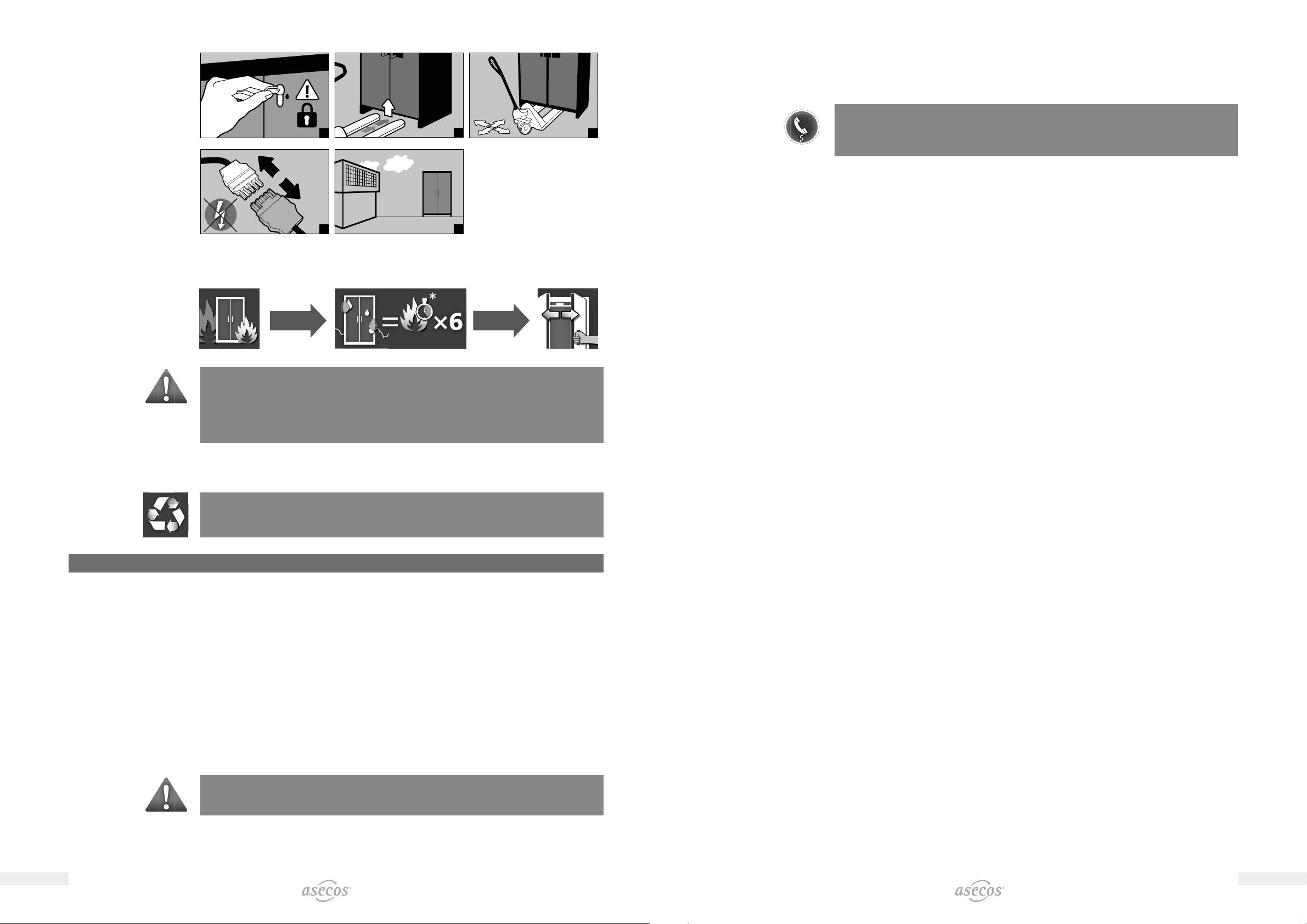
• The pivoting area of the doors is to be kept free at all times; doors are to be kept closed.
• By assigning trained/authorised technical personnel you can prevent the malfunctions, damage and corrosion
damage that result from inappropriate transport.
• Observe the upper limits for stored quantities, loading etc.
• The following substances may not be stored in the cabinets with a fire suppression system: acids, alkalis, mag-
nesium, other metals (in powder form)
Installation and environmental conditions
0–35 °C 30–70 %
1.2. GUARANTEE
The guarantee for this product is agreed between you (the customer) and your dealer (the seller).
As the manufacturer, asecos guarantees the products listed in the operating instructions for a peri-
od of 24 months from the date of delivery.
All model safety equipments are subject to a compulsory annual inspection by specialised sta
authorised by the manufacturer. Otherwise the customer’s guarantee claim against the manufactu-
rer expires.
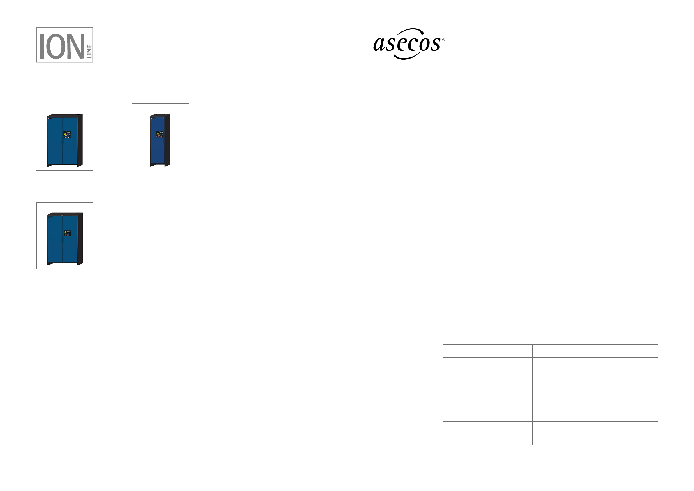
1.3. CABINET DETAILS
Cabinet data logbook (included with the cabinet)
Technical drawing page 19
Technical data page 19
Models Lithium ion batteries
Storing Charging Extraction air unit Fire supression unit Alarm system
BATTERY STORE
IO90.195.060.K1.WDC 4
IO90.195.120.K1.WDC 4
BATTERY STORE PRO
IO90.195.120.K2.WDC 4 4 4
BATTERY STORE & BATTERY STORE PRO
These models are for the passive storage (storage only) of lithium-ion batteries.
With passive storage, new or used lithium-ion batteries are stored for a certain period of time.
GENERAL NOTES
1. NOTES • GUIDELINES • GUARANTEE ............................................. 5
1.1. General safety notes ............................................ 5
1.2. Guarantee ..................................................... 5
1.3. Cabinet details ................................................. 5
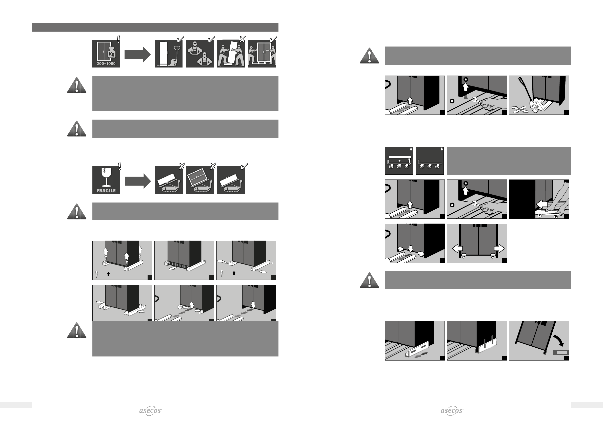
2. TRANSPORT ................................................................. 6
2.1. Tilting the cabinet .............................................. 6
2.2. Dismantling of the transport packaging ............................. 6
2.3. In-plant transport ............................................... 7
2.4. Q-Mover ...................................................... 7
2.5. Titling onto the side wall ......................................... 7
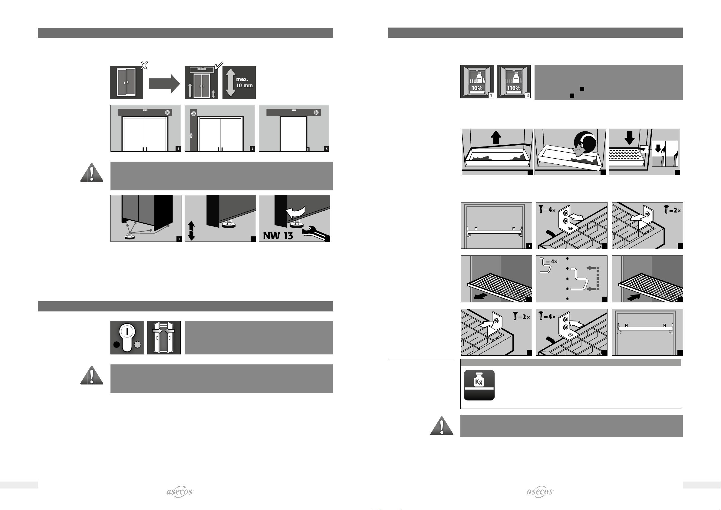
3. INSTALLATION ............................................................... 8
3.1. Alignment of the cabinets ........................................ 8
3.2. Commissioning................................................. 8
4. CLOSING .................................................................... 8
5. INTERIOR FITTINGS ........................................................... 9
5.1. Bottom collecting sump.......................................... 9
5.2. Grid shelves (height adjustable) ................................... 9
5.3. Shelves (height adjustable)...................................... 10
6. STORAGE .................................................................. 10
6.1. Notes on storage and charging ................................... 10
8. BATTERY FIRE • FIRE • DISPOSAL ................................................11
8.1. Fire inside the cabinet (battery fire)................................11
8.3. Disposal ..................................................... 12
9. SAFETY CHECKS............................................................. 12
9.1. All models .................................................... 12
9.2. IO90.195.120.K2.WDC .......................................... 12
9.3. Contact ...................................................... 13
SPECIFIC NOTES
10. IO90.195.120.K2.WDC ........................................................ 14
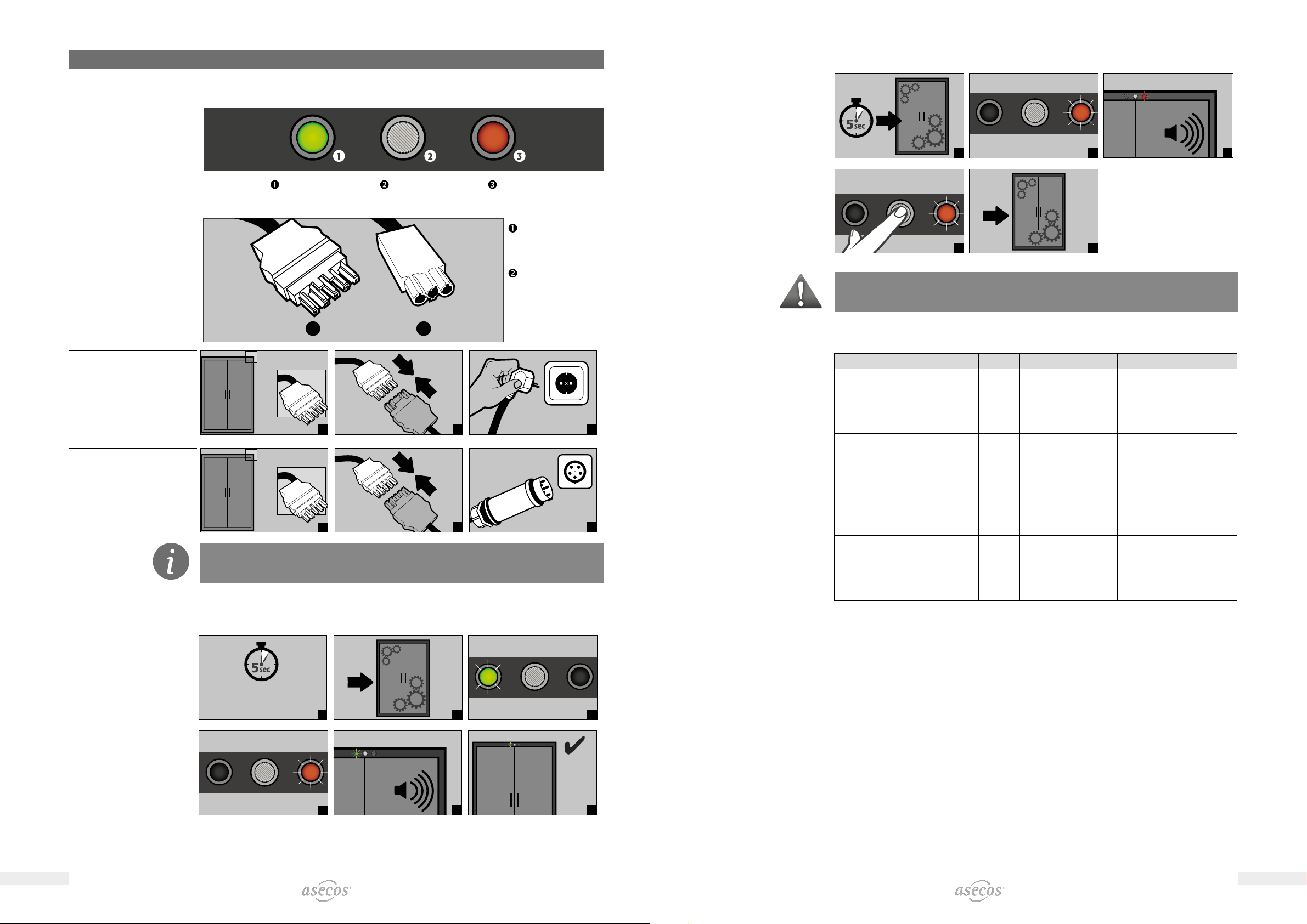
10.1. Connection to the power supply.................................. 14
10.2. SelF test...................................................... 14
10.3. Error during self-test ........................................... 15
10.4. Error and alarm overview. . . . . . . . . . . . . . . . . . . . . . . . . . . . . . . . . . . . . . . . 15
10.5. Potential-free alarm contact ..................................... 16
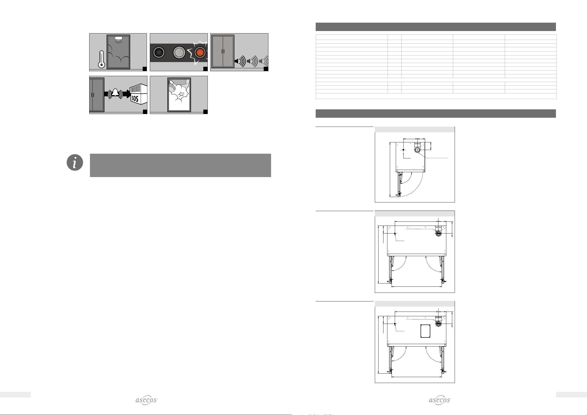
10.6. Warning/fire suppression system ................................. 16
10.7. Warning message .............................................. 17
10.8. Alarm stage 1 ................................................. 17
10.9. Alarm stage 2 ................................................. 18
10.10. False alarm of the smoke detector ................................ 18
11. TECHNICAL DATA............................................................ 19
12. TECHNICAL DRAWING........................................................ 19

67GENERAL NOTESGENERAL NOTES
2. TRANSPORT
ATTENTION:
Transport the cabinet in an upright position on a pallet truck, tied and secured against slipping, until the final
place of installation is reached. The transport locks in the door joints may only be removed directly at the
place of installation! Inappropriate transport can lead to concealed damage to the fire protection insulation!
We can only guarantee the necessary quality if the cabinet is transported to the place of its use by our
specially trained sta.
ATTENTION:
The doors must be locked prior to transport! The extraction unit is inside the cabinet and is only mounted
after the in-plant transport to the place of use.
2.1. TILTING THE CABINET
ATTENTION:
Tilting the cabinet may only be done without jolts!
2.2. DISMANTLING OF THE TRANSPORT PACKAGING
1
= 4× 2
= 8× 3
456
ATTENTION
Cabinet width 600 mm
The clearance drive-in width of the base is 520 mm
You must observe this when selecting a pallet truck! Appliances with a carrying width larger
than the drivein width may not be used
2.3. INPLANT TRANSPORT
• is also possible without transport locks (inserted as standard in the door joints)
ATTENTION:
The doors must be locked prior to transport! The extraction unit must be removied from the
top of the cabinet
1
2
= 4×
3
2.4. QMOVER
• Order no. HF.I.23526, available from your authorised dealer
a: upright transport
b: upright transport through standard doors
(clearance height 1986 ± 2 mm)
12
= 4×
3
45
ATTENTION:
Damage to the cabinet must be reported in writing without delay!
2.5. TITLING ONTO THE SIDE WALL
• is only possible with the optionally available tilting bracket (order no. HF.V.27665)
123

89GENERAL NOTESGENERAL NOTES
3. INSTALLATION
3.1. ALIGNMENT OF THE CABINETS
ATTENTION:
Door elements must not scrape against the fire prevention seals in the fold of the door when opening and
closing! Doors with an automatic closing mechanism must close automatically from every position and the
lock must be able to lock!
4× 2
max. 2× (!) 3
3.2. COMMISSIONING
• Before the first commissioning, the user must carry out an examination of the safety storage cabinet for pos-
sible damage, such as defective or loose sealing elements, correct alignment and perfect functioning of the
door elements (hinges, locking system and, if applicable, door closer).
• Use the cabinet and accessories only if they are in an orderly condition.
4. CLOSING
The doors are permanently self-closing.
The cabinets feature a cylinder lock with closing status indicator.
They can be integrated into a master key system.
ATTENTION:
The owner/user must ensure that all doors are kept closed whenever the contents of the cabinet are not
being accessed. In general, it must be noted that the cabinets do not possess an emergency unlocking
facility. This means that persons trapped inside the cabinet cannot free themselves!
5. INTERIOR FITTINGS
5.1. BOTTOM COLLECTING SUMP
12
According to EN 14470-1: A bottom collecting sump must be
installed below the lowest storage level. The bottom collecting sump
must be able to hold a minimum volume of 10 % of all the containers
stored in the cabinet 1or at least 110 % of the volume of the largest
single container 2, whichever of these volumes is larger.
Leaks:
• Liquid in the sump is to be collected using suitable means.
• The choice of means is your own responsibility.
1
2
3
5.2. GRID SHELVES HEIGHT ADJUSTABLE
2
3
4
5
6
7
8
9
Load capacities IO90.195.120.K1.WDC / IO90.195.120.K2.WDC*
max. 180 kg
*ATTENTION:
Model IO90.195.120.K2.WDC: The positions of the fire suppression device, smoke detector and thermal
sensor must not be changed when changing the height of the grid shelves.

10 11GENERAL NOTESGENERAL NOTES
5.3. SHELVES HEIGHT ADJUSTABLE
2
3
4
5
6
7
8
9
Load capacities IO90.195.060.K1.WDC O90.195.120.K1.WDC / IO90.195.120.K2.WDC*
max. 25 kg max. 75 kg
max. 50 kg
Only with
Special interior equipment:
Order No. 38516
Order No. 38517
Order No. 38518
Order No. 38519
*ATTENTION:
Model IO90.195.120.K2.WDC: The positions of the fire suppression device, smoke detector and thermal
sensor must not be changed when changing the height of the grid shelves.
6. STORAGE
ATTENTION:
Never store obviously damaged lithium-ion batteries inside buildings. Dispose of them without delay in
disposal containers that are provided outside the building and approved for transport.
6.1. NOTES ON STORAGE AND CHARGING
Storage
It is recommended to store new and used lithium-ion batteries separately (each on a dierent storage level)
in the safety storage cabinet.
Occupation of the storage levels
Grid shelves may be covered only up to 60% by battery chargers and batteries in order to ensure trouble-free
operation of the fire suppression system and sucient air circulation
ATTENTION:
It is not permitted to occupy the complete area of the grid shelves
IO90.195.120.K2.WDC:
The following substances may not be stored in the cabinets with a fire suppression system: acids, alkalis,
magnesium, other metals (in powder form).
ATTENTION:
In the area in front of the fire suppression unit there is a
distance of at least 150 mm to be observed.
Li-Ion Li-Io
n
150 mm
7. VENTILATION
CAUTION
The fire protection valves near the supply and extraction air connections are safety and
maintenance-relevant components.
In order to check the correct function or to replace a defective element, please note that when connecting
to an exhaust air system, flexible connection hoses or sliding pieces are used to ensure easy removal and
reassembly of the exhaust air connection.
Ventilation wheel for technical ventilation
The ventilation wheel serves as an indicator for correct ventilation.
If the wheel turns, the necessary 10-fold air recirculation rate is exceeded.
8. BATTERY FIRE • FIRE • DISPOSAL
CAUTION
Following a battery fire and the triggering of the fire suppression system, the safety storage cabinet must
be subjected to a thorough inspection so that both fire protection and CE conformity are retained. For this
purpose the cabinet must be handed over to asecos GmbH‘s main factory in Gründau, where the specialist
department – depending on the extent of the damage – will appraise the economic viability and technical
possibilities of a repair. The customer then receives a quotation either for a repair or for an exchange, which
can be forwarded to the responsible insurance company.
8.1. FIRE INSIDE THE CABINET BATTERY FIRE
• For fast transport the cabinets are equipped with a transport base.
• The cabinets are automatically disconnected from the mains supply in the case of transport.
ATTENTION:
Prior to transport the doors must be locked and the extraction unit removed from the cabinet!
Transport may only be carried out by technical personnel!

12 13GENERAL NOTESGENERAL NOTES
1
2
3
4
5
8.2. OPENING THE CABINET AFTER THE FIRE
*ATTENTION:
Only open the cabinet after it has cooled down. This is 6 times the fire duration!
Only authorised personnel (e.g. fire brigade) may open the cabinet!
Depending upon the duration of the fire an ignitable vapour/air mixture may have formed; therefore remove
all sources of ignition within a 10 metre radius of the cabinet before opening it use only spark-free tools
open the cabinets with extreme caution
8.3. DISPOSAL
The models can be disposed of once they have been dismantled and the materials sorted. They are free
from materials that have to be disposed of as special waste.
9. SAFETY CHECKS
9.1. ALL MODELS
As safety equipment (according to §4 Paragraph 3 Workplace Ordinance, §10 German Ordinance on Industrial
Health and Safety and German Statutory Accident Insurance [DGUV] rule no. 108-007) the cabinets have to
be checked for safety at least once per year. The next checking date can be taken from the check sticker on
the outside of the door. This annual check can be carried out with the necessary care, and for securing your
warranty claims in the case of fire, only by an authorised asecos employee (refer also to our service brochure
regarding this).
9.2. IO90.195.120.K2.WDC
A necessary service is automatically indicated by the cabinet by a flashing green LED.
Within the context of the annual check, the fire suppression system, smoke detector and sensors will be che-
cked in addition to the checking of all safety-related parts.
ATTENTION
In accordance with DIN 14676 the proper function of the smoke detector must be checked at least once
per year.
In addition, we recommend the regular visual inspection of the battery chargers, batteries and connecting
cables.
9.3. CONTACT
In case of damage please contact your dealer in order to have the cabinet repaired using original spare parts.
The cabinets can be cleaned with a mild household cleaner and a soft cloth.
CONTACT
In the case of defects or complaints about our products (within and also after the warranty period), and for
requesting safety checks or taking out a service contract, please contact our service hotline on:
Tel: +44 1785 22 70-90 info@asecos.co.uk

14 15SPECIFIC NOTES: BATTERY STORE PROSPECIFIC NOTES: BATTERY STORE PRO
10. IO90.195.120.K2.WDC
10.1. CONNECTION TO THE POWER SUPPLY
LED: Operating (green) RESET BUTTON LED: Error (red)
Connections on the headpiece:
1 2
Mains plug connector
Potential-free switch
contact
Connection to the
power supply
1
2
230 V
3
Connection to the power
supply with 400 V
(optional with item
HF.E.32822)
1
2
400 V
3
CAUTION:
Subsequent retrofitting is possible using the plug connection, so that no intervention in the electrical
components is required.
10.2. SELF TEST
Starts 5 seconds after
connection to the
mains supply
1
2
3
4
5
6a
10.3. ERROR DURING SELFTEST
1
2
5
3
5
sec
4
5
ATTENTION:
After pressing the reset button, the self-test begins again. If the error persists, please contact the asecos
Service Dept.
10.4. ERROR AND ALARM OVERVIEW
EVENT LED GREEN LED RED ACOUSTIC ALARM ACTIONS
Error during self-test o on 5 signal tones 1.) Restart with RESET button
If error persists:
2.) Contact Service
Service interval
reached
flashing o o Contact Service
Power failure Flashes every
20 seconds
o 3 short signal tones
every 60 seconds
Check power supply
Warning message:
Temperature in the
cabinet >50 °C
o on long tone interval
(every 2 seconds for
250 ms)
see 10.7
Alarm stage 1:
Smoke detector
detects smoke in the
cabinet
o on medium tone interval
(every 0.5 seconds for
250 ms)
see 10.8
Alarm stage 2:
Smoke detector
detects smoke in the
cabinet, Tempera-
ture in the cabinet
>70 °C
o flashing short tone interval
(every 0.25 seconds for
125 ms)
see 10.9

16 17SPECIFIC NOTES: BATTERY STORE PROSPECIFIC NOTES: BATTERY STORE PRO
10.5. POTENTIALFREE ALARM CONTACT
NOTE:
The potential-free alarm contact is for connecting a signal to a control room/control centre. A direct
connection to a fire alarm system is not recommended or may only be done in consultation with those
responsible for the system.
In general, however, the connection of the signal to a manned control room/control centre is
always recommended!
The connection of the potential-free switch contact must always be done by the customer (not a service
item).
(AC) / (DC)
(AC) / (DC)
Connector
Internal
alarm contact
Connection instructions
• Use only the supplied mating part (colour-coded black) to the plug for the connection
• The connection must be done by a qualified electrician
• The contact is designed for a max. DC voltage of 30 V or a max. AC voltage of 230 V
• The maximum current load is 10 A
• The switch contact is normally closed!
• The switch contact opens as soon as mains voltage is present and no error is pending (device is „ready to
operate“)
10.6. WARNING/FIRE SUPPRESSION SYSTEM
• The warning/fire suppression system oers the option of connection to a constantly manned building ma-
nagement system or fire alarm centre.
• Make use of this option so that trained rescue personnel can be quickly alerted and be on-site in a very short
time and, following an initial assessment of the situation, immediately initiate further measures (for example,
transporting the cabinet out of the building).
• The extinguishing agent, based on calcium carbonates, is harmless in the necessary extinguishing agent con-
centration and has no harmful eects on the human organism
• In case of triggering, the aerosol is ejected at a high temperature and temperatures of over 300°C are briefly
generated in front of and on the housing of the fire suppression cartridge (according to the manufacturer‘s
data, a minimum distance to combustible materials need not be maintained; however, a distance of at least
150 mm to the fire suppression cartridge should generally be maintained)
• After triggering of the fire suppression cartridge, ventilate the room and the cabinet well, observing the instruc-
tions in point 8.
ATTENTION:
The complete warning/fire suppression system is active only with mains operation.
The integrated smoke detector is part of the entire fire suppression system (direct power supply)
10.7. WARNING MESSAGE
>50 °C
1
2
3
sofern
aufgeschaltet
4
Actions
• immediate visual inspection of the system by the company‘s own qualified personnel
• initiation of necessary actions
• if the interior temperature falls below 50 °C, the system returns to normal operation and the visual and acoustic
signals are switched o.
10.8. ALARM STAGE 1
!
1
2
3
sofern
aufgeschaltet
4
Actions
• immediate visual inspection of the system by technical personnel (e.g. fire brigade)
• subsequently, initiation of necessary actions
• if the smoke detector does not detect any further smoke development in the cabinet, the system can be reset
to normal operation by briefly disconnecting the mains voltage

1918 SPECIFIC NOTES: BATTERY STORE PRO
10.9. ALARM STAGE 2
>70 °C
1
2
3
sofern
aufgeschaltet
4
5
Actions
• immediate visual inspection of the system by technical personnel (e.g. fire brigade)
• subsequently, initiation of necessary actions
• See 8.1 for the transport of the cabinets out of the building
ATTENTION:
Afterwards the complete system can only be assessed and if possible reset to normal operation
by authorised asecos service technicians. At least the fire suppression unit and the smoke
detector need to be replaced for this.
10.10. FALSE ALARM OF THE SMOKE DETECTOR
• By interrupting the power supply for a few seconds, the smoke detector is reset and the system returns to
normal operation
11. TECHNICAL DATA
IO90.195.060.K1.WDC IO90.195.120.K1.WDC IO90.195.120.K2.WDC
Type minutes 90 90 90
Dimensions B x T x H exterior mm 599 x 615 x 1953 1193 x 615 x 1953 1193 x 615 x 1953
Dimensions B x T x H interior mm 450 x 522 x 1647 1050 x 522 x 1647 1050 x 522 x 1647
Weight of empty cabinet kg 265 424 424
Distributed load kg/m² 894 531 531
Exhaust Air DN 75 75 75
Entry width of transport base mm 526 1120 1120
Entry height of transport base mm 90 90 90
Max. load of shelves kg 25 75 (50)* /(180)* 75 (50)* / (180)*
Power consumption of the control electronics
Power consumption in operation W – – 1,5
Nominal voltage V – – 230
Frequency Hz 50/60
* Information applies to special interior equipment, see chapter 5.2
12. TECHNICAL DRAWING
IO90.195.060.K1.WDC
290
1129
156
(155)
90°
Fresh air Exhaust air DN 75
Top view
IO90.195.120.K1.WDC
884
1166
156
156
(155)
1017
90°
90°
Fresh air
Exhaust air DN 75
Top view
IO90.195.120.K2.WDC
884
1166
156
156
(155)
1017
90°
90°
Fresh air
Exhaust air DN 75
Top view

20 SPEZIFISCHE HINWEISE: BATTERY CHARGE
asecos GmbH
Abt. Kundendienst
Weiherfeldsiedlung 16-18
D-63584 Gründau
Fax: +49 60 51 – 92 20-10
www.asecos.com
Ihr Fachhändler:
Your partner:
Uw partner:
Votre partenaire :
Su distribuidor:
su richiesta:
This manual suits for next models
4
Table of contents
Other asecos Storage manuals

asecos
asecos V-CLASSIC-90 User manual

asecos
asecos ION-STORE-90 User manual

asecos
asecos V Series User manual

asecos
asecos F Series User manual

asecos
asecos ION-CLASSIC-90 User manual

asecos
asecos ION LINE User manual

asecos
asecos FX Series User manual

asecos
asecos Q Series User manual

asecos
asecos FX Series User manual

asecos
asecos Q-LINE Q15 User manual