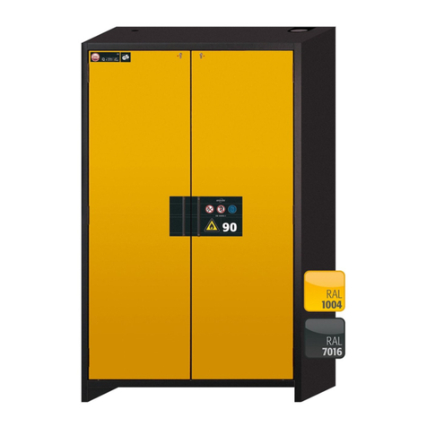
asecos G-CLASSIC-30 User manual

EN
Years5
Warranty*
USER MANUAL
Gas cylinder cabinets
according to EN14470-2
5 YEARS WARRANTY
Upon conclusion of an asecos service
and maintenance agreement (BasicPlus
tari ) with a fixed term of 5 years, you
will get a warranty extension for a
maximum of 5 years for your safety
storage cabinet.
For detailed information about our
warranties please visit:
EP.V.34173.00 | 10/2023

G30.205.140 G30.205.120 G30.205.090 G30.205.060
G30.205.060.R
G90.205.140 G90.205.120 G90.205.090 G90.205.060
G90.205.060.R
G90.205.060.2F
G90.205.060.2F.R
G90.145.060
G90.145.060.R
G-CLASSIC-30
G-ULTIMATE-90

Contact
Company
Street
Name of contact person
email
Serial numbers of safety storage cabinets
Phone No.
Postal code Town
YOUR PERSONAL DOCUMENTATION TO THE asecos
SAFETY CABINET
Dear Customer,
you have made a decisive investment in safety for your company by purchasing this asecos safety
storage cabinet. You now own an innovative product made of top-quality materials guaranteeing
the highest quality standards.
asecos safety storage cabinets have complete authorisation documents. We archive the authori-
sation documents for every individual cabinet, keeping them ready for you should you ever need
them (e.g. for a works inspection or similar). Simply request them using this form.
Tear of or copy that page and return to us by fax with your address and serial number of the
cabinet on it.
Yours sincerely
asecos GmbH
asecos GmbH
Customer service
Weiherfeldsiedlung 16–18
D-63584 Gründau
Fax: +49 60 51 - 92 20-10
email: service asecos.com

4
EN OPERATING INSTRUCTIONS
Dear customer,
Thank you very much for purchasing a safety storage cabinet from our company, with which you have made
a decisive investment in the safety within your company. Our safety storage cabinets make the storage of
hazardous materials at the workplace safe and convenient for you.
Please read these operating instructions very carefully. Get to know the advantages and simple operability of
our safety storage cabinets in detail. This simplifies the daily handling of hazardous materials for you.
Many thanks
Your asecos team
1. NOTES • GUIDELINES • GUARANTEE ...........................................5
1.1. General safety notes ............................................... 5
1.2. Guarantee ........................................................ 5
1.3. Cabinet Details .................................................... 5
2. TRANSPORT ...............................................................5
2.1. In general ........................................................ 5
2.2. Tilting the cabinet ................................................. 6
3. ERECTION • COMMISSIONING • FUNCTION ......................................6
3.1. Alignment Of The Cabinets .......................................... 6
3.2. Commissioning .................................................... 6
4. CLOSING MECHANISMS .....................................................6
4.1. Types Of Closing .................................................. 6
4.2. Opening of double wing door ........................................ 7
5. INTERIOR FITTINGS .........................................................7
5.1. Mounting rails ..................................................... 7
5.2. Cylinder retainer ................................................... 7
5.3. Cylinder retainer sidewall ............................................ 8
5.4. Rolling ramp ...................................................... 8
5.5. Shelf and heavy duty grid ........................................... 9
5.6. shelf, inclined version .............................................. 9
6. PIPE / CABLE LEADTHROUGH. . . . . . . . . . . . . . . . . . . . . . . . . . . . . . . . . . . . . . . . . . . . . . . . .9
6.1. Diameter / number of pipelines / cables ............................... 9
6.2. Pipeline material .................................................. 9
6.3. Drill holes and drilling distances ..................................... 10
6.4. Implementation areas ............................................. 10
6.5. Ermeto screw connection .......................................... 10
6.6. Closing open holes ............................................... 10
7. STORAGE. . . . . . . . . . . . . . . . . . . . . . . . . . . . . . . . . . . . . . . . . . . . . . . . . . . . . . . . . . . . . . . . .11
8. EARTHING ................................................................11
8.1. Ground connection ................................................11
8.2. Grounding PREMIUM .............................................. 12
9. VENTILATION .............................................................12
9.1. General facts .................................................... 12
9.2. Notes for Fire protection collars • Air vents • Fire protection valves ......... 12
9.3. Montage of fire protection sleeve .................................... 13
9.4. Installation of the ventilation socket .................................. 13
9.5. Installation of the fire protection valves ............................... 13
10. FIRE • DISPOSAL. . . . . . . . . . . . . . . . . . . . . . . . . . . . . . . . . . . . . . . . . . . . . . . . . . . . . . . . . . .14
10.1. Opening the cabinet after the fire .................................... 14
10.2. Disposal ........................................................ 14
11. SAFETY CHECKS ...........................................................14
11.1. Wearing parts .................................................... 14
11. 2 . Contact ......................................................... 14
12. TECHNICAL DRAWING ......................................................16
13. TECHNICAL DATA ..........................................................17
5
EN
1. NOTES • GUIDELINES • GUARANTEE
1.1. GENERAL SAFETY NOTES
• Observe applicable statutes and regulations, and the notes in these operating instructions, when handling
hazardous materials
• The on-site installation conditions are to be observed (e.g. bolting the cabinets to the building).
• The instructions of the supervisory engineering department must be followed.
• Observe accident prevention regulations and workplace ordinance
•Ensure that the necessary safety checks are only carried out by authorised sta using original
spare parts
• Only use the cabinet after having been properly instructed; access is to be forbidden to unauthorised persons.
• By assigning trained/authorised technical personnel you can prevent the malfunctions, damage and corrosion
damage that result from inappropriate transport.
• The pivoting area of the doors is to be kept free at all times; doors are to be kept closed
• Observe the upper limits for stored quantities, loading etc.
• To avoid explosive atmospheres and harmful vapours, sucient technical ventilation is strongly recommended.
Please observe the instructions for connection to an exhaust air system.
• Before the initial commissioning, the safety storage cabinet is to be examined by the user for possible dam-
age.
Set-up requirements
0–35 °C 30–70 %
1.2. GUARANTEE
The guarantee for this product is agreed between you (the customer) and your dealer (the seller). As the
manufacturer, asecos guarantees the products listed in the operating instructions for a period of 24 months
from the date of delivery. All model safety equipment are subject to a compulsory annual inspection by spe-
cialised sta authorised by the manufacturer. Otherwise the customer’s guarantee claim against the manufac-
turer expires.
1.3. CABINET DETAILS
Cabinet data: logbook (included with the cabinet)
Technical drawing: see appenidix
Technical data: table in appendix
A complete overview of the models can be found at the start of the operating instructions.
G-CLASSIC-30 • G-ULTIMATE-90
These models are tested, certified and marked according to requirements of BS EN 14470-2. They are intend-
ed for the storage and emptying of gas cylinders in buildings in accordance with the valid national regulations.
2. TRANSPORT
2.1. IN GENERAL
CAUTION:
Transport the cabinet in an upright position on a pallet truck, tied and secured against slipping, until the
final place of installation is reached.The transport locks in the door joints may only be removed directly
at the place of installation! Inappropriate transport can lead to concealed damage to the fire protection
insulation!We can only guarantee the necessary quality if the cabinet is transported to the place of its use
by our specially trained sta.

6
EN 2.2. TILTING THE CABINET
CAUTION:
Tilting the cabinet may only be done without jolts!
3. ERECTION • COMMISSIONING • FUNCTION
3.1. ALIGNMENT OF THE CABINETS
3.2. COMMISSIONING
• Before putting into operation for the first time, the user must carry out an examination of the safety storage
cabinet for possible damage, such as defective or loose sealing elements, correct alignment and perfect func-
tioning of the door elements.
Use the cabinet and accessories only if they are in an orderly condition.
4. CLOSING MECHANISMS
4.1. TYPES OF CLOSING
Doors closable only by hand CYLINDER LOCK (suitable
for master key systems)
ATTENTION:
The owner/user must ensure that all doors are kept closed whenever the contents of the cabinet are
not being accessed. In general, it must be noted that the cabinets do not possess an emergency unlocking
facility. This means that persons trapped inside the cabinet cannot free themselves!

7
EN
4.2. OPENING OF DOUBLE WING DOOR
G-ULTIMATE-90
1
2
3
4 5 6
G-CLASSIC-30
1
2
3
4
5. INTERIOR FITTINGS
5.1. MOUNTING RAILS
• for fittings for pressurised gases, height-adjustable
5.2. CYLINDER RETAINER
[A] G-ULTIMATE-90
[B] G-CLASSIC-30
A
B
apermanently mounted on the rear wall
btension belts for securing the gas cylinders
cadjustable in depth (G-ULTIMATE-90)

8
EN
Adjustable in depth with G-ULTIMATE-90
1
2
3
Cylinder retainerG90.205.060.2F
1
4×
2
3
4×
4
5
5.3. CYLINDER RETAINER SIDEWALL
SIDE CYLINDER RETAINER
(adjustable without tools)
• is hooked into a mounting rail and is adjustable in height
SIDE CYLINDER RETAINER
(bolted)
= 4 mm
= 20 mm
• is adjustable in height and bolted to the side wall
NOTE Model G90.205.060.2F(R)
Due to the use of special fire protection panels, it is strictly forbidden to mount components or drill holes on
the side walls!
5.4. ROLLING RAMP
• latches automatically in the folded condition

9
EN
STANDARD
8
4
2
COMFORT
5.5. SHELF AND HEAVY DUTY GRID
The shelf or heavy duty grid will be installed in the factory at a height of 1100 mm. Special positions are
possible but require prior technical clarifications as well as the creation of a chargeable approval / assembly
drawing.
5.6. SHELF, INCLINED VERSION
Storage of small gas cylinders
The inclined shelves are installed in the factory in a predefined position. By default it is possible to store
gas cylinders with a length of up to 590 mm and a diameter of 100 mm. The storage of gas cylinders with
dierent dimensions as well as a special positioning of the shelves is possible, however this will require a prior
technical clarification as well as the creation of a chargeable approval / assembly drawing.
6. PIPE / CABLE LEADTHROUGH
130 mm > 200 mm
HSS
CAUTION
Do not use wood or flat drills. The exclusive type of drill is HSS.
6.1. DIAMETER / NUMBER OF PIPELINES / CABLES
NOTE
The max. permissible diameters according to DIN EN 14470-2 must be observed!
›Outer diameter 10 mm for pipes
›Outer diameter 20 mm for cable
The number of passes shall be reduced to the minimum necessary.
A maximum of 3 pipe penetrations and 2 cable penetrations per compressed gas cylinder are permitted.
6.2. PIPELINE MATERIAL
It is recommended to use the tubes made of stainless steel or a material with similar thermal conductivity
to maintain the fire resistance determined and specified during the test. The use of copper pipes with a
maximum outer diameter of 10 mm is permitted without negatively aecting the tested fire resistance of the
cabinets.

10
EN 6.3. DRILL HOLES AND DRILLING DISTANCES
The drill hole may be drilled max. 1 mm larger than the outer diameter of the pipeline or electric cable used.
The pipeline or cable can be routed through the cabinet ceiling without any further insulation measures.
Example
• Pipeline with 10 mm outer diameter = diameter from borehole 11 mm
• Cable with 20 mm outer diameter = diameter from drill hole 21 mm
CAUTION
A distance of min. 20 mm on all sides between the holes must be observed.
min 20 mm
6.4. IMPLEMENTATION AREAS
The possible feed-through area for pipes and cables through the cabinet ceiling is marked accordingly on the
inside and outside.
• The holes can be drilled from both directions (from the inside to the outside or vice versa)
• Note, however, that depending on the pressure during drilling, the hole may break out on the opposite side.
For optical reasons, drilling from the inside out is therefore recommended.
• When drilling from the inside, you must maintain a distance of at least 5 cm from the rear wall. If you need to
drill further back, drilling is then only possible from the outside in.
6.5. ERMETO SCREW CONNECTION
• Thanks to the R3/8” internal threads a conventional ermeto screw connection can be mounted in the second
step.
6.6. CLOSING OPEN HOLES
CAUTION:
The max. permissible lead-through diameters in accordance with BS EN 14470-2 (10 mm for pipes, 20 mm
for cables) are to be observed!
All unused holes in the cabinet wall must be properly sealed with suitable fire protection putty (ROKU
1000, order no. 6520) over the full area and the complete wall thickness.
It is recommendable to manufacture the pipes from rustproof stainless steel or a material with similar
conductive properties in order to maintain the fire resistance characteristics established and specified during
the test.

11
EN
1
2
ROKU 1000
3
3
ROKU 1000
4
5
3
6
7
7. STORAGE
•The total volume of the stored gas cylinders must not exceed 210 l + 10 l (purging gas cylinder).
Applicable for all models: Depending on the type class of the cabinet, observe therespective valid national
regulations!
8. EARTHING
8.1. GROUND CONNECTION
G-ULTIMATE-90
All G-ULTIMATE-90 models have a ground connection. The cabinet body (side and roof panels) is metallically
conductively connected to each other via the ground connection. The ground connection is prepared for the
creation of the on-site potential equalization. The corresponding material is included with the product and
must be mounted on site at the appropriate location on the head section.
G-CLASSIC-30
The G-CLASSIC-30 models do not have a ground connection.
A
B
B
B
B
C
C
D
D
E
F
G

12
EN F
Legende
A 1 × screw M6×30
B 4 × washer Ø 6,4
C 2 × spring washer Ø 6,4
D 2 × serrated lock washer Ø 6,4
E 1 × nut with clamping part
F earthing wire with ring cable lug (on-site
connection)
G metal part of the safety storage cabinet
8.2. GROUNDING PREMIUM
Only available in conjunction with cabinet for factory assembly.
Optionally, the G-ULTIMATE-90 cabinets are equipped as follows for an additional charge:
• additional metallic conductive connection of door plates, door handles and baseboard with the cabinet body
(article 39621 / HF.E.34157)
9. VENTILATION
9.1. GENERAL FACTS
• If installed on an exhaust system, a check must be carried out to ensure proper connection to the system (e.g.
using a smoke tube)
DN
75 NOTES
The fire protection valves near the supply and extraction air connections are safety and maintenance-rel-
evant components.
CAUTION:
In the case of gas cylinder cabinets that are connected to a technical exhaust system, the minimum air recir-
culation rate must be fulfilled according to BS EN 14470-2. The ventilation must be permanent in operation
and must lead out to a safe place in the open air. The pressure drop of the cabinet must not exceed 150 Pa.
The inflow velocity of the air must be at least 20 cm/s.
Minimum air recirculation rate during storage of:
flammable/oxidizing gases toxic gases
9.2. NOTES FOR FIRE PROTECTION COLLARS • AIR VENTS • FIRE

13
EN
PROTECTION VALVES
NOTE for mounting the fire protection collars, ventilation nozzles and fire protection valves
The fire protection collars, ventilation nozzles or fire protection valves are not mounted at the
factory for transport reasons and are included with the cabinet.
›The fire protection valves/collars are also a decisive factor for the tested fire resistance of the cabinets in
case of fire!
›It is therefore essential that these are fitted to the openings for supply and exhaust air after the safety
storage cabinet has been installed at the place of use.
›The fire protection collars, ventilation nozzles or fire protection valves must also be installed if no technical
ventilation of the safety cabinet is to take place!
›Any fire protection seals in the holes must not be removed! The connection to a technical exhaust air
system is always made at the connection piece / fire protection valve on the right-hand side (seen from
the front).
9.3. MONTAGE OF FIRE PROTECTION SLEEVE
FOR MODELS:
G90.205.140
G90.205.120
4×
(4×30 mm)
4×
(5×25 mm)
4×
(5×25 mm)
9.4. INSTALLATION OF THE VENTILATION SOCKET
For Models:
G90.205.090
G90.205.060(2F)
4×
(4×30 mm)
9.5. INSTALLATION OF THE FIRE PROTECTION VALVES
G-CLASSIC-30
After installation of the safety cabinet at the final point of use the fire protection valves (enclosed in the
cabinet) which have been demounted to avoid transport damages have to be fixed on the air inlet and
outlet again. The valves have also to be mounted even if there will be no technical ventilation of the safety
cabinet! For mounting of the valves (see picture) position them on the air inlet and outlet and use the screws
enclosed (4 pieces/valve) to fix them on the cabinet top (do not remove the fire protection sealings already
installed in the air inlet and outlet!

14
EN 10. FIRE • DISPOSAL
10.1. OPENING THE CABINET AFTER THE FIRE
ATTENTION:
Only authorised personnel (e.g. fire brigade) may open the cabinet!
Depending upon the duration of the fire an ignitable vapour/air mixture may have formed; therefore remove
all sources of ignition within a 10 metre radius of the cabinet before opening it.
Use only spark-free tools !
Open the cabinets with extreme caution !
10.2. DISPOSAL
The models can be disposed of once they have been dismantled and the materials sorted.
11. SAFETY CHECKS
As safety equipment the cabinets have to be checked for safety at least once per year. The next checking date
can be taken from the service sticker on the outside of the door. This annual check can be carried out with the
necessary care, and for securing your warranty claims in the case of fire, only by an authorised asecos employ-
ee (refer also to our service brochure regarding this).
In addition, we recommend that you carry out a daily and monthly functional check:
• perfect function of the doors:
- hinges
- locking system
- door closer
- door open arrest system
• correct seating and condition of the fire protection seals
Case of damage
In case of damage please contact your dealer in order to have the cabinet repaired using original spare parts.
The cabinets can be cleaned with a mild household cleaner and a soft cloth.
11.1. WEARING PARTS
Various safety-related components of the safety storage cabinet are wearing parts and must be replaced at
regular intervals by asecos Service. A list of the parts aected for your safety cabinet is available on request
from [email protected].
11.2. CONTACT
CONTACT:
In the case of defects or complaints about our products (within and also after the warranty period), and for
requesting safety checks or taking out a service contract, please contact our service hotline on:
Tel: +44 1785 22 70-90 | info@asecos.co.uk (for great Britain and Ireland)
Tel: +49 1805 92 20 92 | service@asecos.com (international)

15
EN

16
EN
230
1191
96
max. 180°
max. 180°
584
1337
126
50
150325
1206
Earthing link
Exhaust air DN 75
Pipe lead-through area
Fresh air
Top view
G90.205.140
230
991
max. 180°
484
126
150325
96
max. 180°
1238
55
1006
Earthing link
Exhaust air DN 75
Pipe lead-through area
Fresh air
Top view
G90.205.120
230
691
max. 180°
334
55
126
150
325
96
max. 180°
1089
706
Earthing link
Exhaust air DN 75
Pipe lead-through area
Fresh air Ø75
Top view
G90.205.090
183
126
205270
96
max. 180°
1134
406
Earthing linkExhaust air DN 75
Fresh air Ø75
Top view
Pipe lead-through area
G90.205.060 G90.205.060.R
G90.145.060 G90.145.060.R
G90.205.060.2F G90.205.060.2F.R
1294 / 1194
325
82
150
584 / 484
max. 180°
max. 180°
1206/1006
96
Exhaust air DN 75
Earthing link
Fresh air Ø75
Pipe lead-through area
Top view
G30.205.140
230 484
1006
96
1194
1029
150
325
82
max. 180°
max. 180°
Top view
Earthing link
Exhaust air DN 75
Pipe lead-through area
Fresh air Ø75
G30.205.120
230
1045 / 1135
334/184
325
82
150
96
max. 180°
706 / 406
Exhaust air DN 75
Earthing link
Fresh air Ø75
Pipe lead-through area
Top view
G30.205.090
230 184
40696
max. 180°
1135
325
82
150
Top view
Exhaust air DN 75
Fresh air Ø75 Earthing link
Pipe lead-through area
G30.205.060 G30.205.060.R
12. TECHNICAL DRAWING

17
EN
Key for “Technical data” table
External dimen-
sions W x D x H
Internal dimen-
sions W x D x H
Type Weight of empty
cabinet
Maximum load Distributed load Air change 120
times
G-LINE type 90 kg kg kg/m² m³/h Pa
G90.205.140 1398 x 615 x 2050 mm 1245 x 400 x 1858 mm G90 690 600 571.00 111 143
G90.205.120 1198 x 615 x 2050 mm 1045 x 400 x 1858 mm G90 610 600 625.00 93 103
G90.205.090 898 x 615 x 2050 mm 745 x 425 x 1858 mm G90 490 600 752.00 66 147
G90.205.060 598 x 615 x 2050 mm 445 x 425 x 1858 mm G90 365 600 999.00 42 85
G90.205.060.R 598 x 615 x 2050 mm 445 x 425 x 1858 mm G90 365 600 999.00 42 85
G90.145.060 598 x 615 x 1450 mm 445 x 425 x 1246 mm G90 278 600 909.00 28 42
G90.145.060.R 598 x 615 x 1450 mm 445 x 425 x 1246 mm G90 278 600 909.00 28 42
G90.205.060.2F 598 x 615 x 2050 mm 445 x 425 x 1858 mm G90 365 600 999.00 45 76
G90.205.060.2F.R 598 x 615 x 2050 mm 445 x 425 x 1858 mm G90 365 600 999.00 45 76
G-LINE type 30 kg kg kg/m² m³/h Pa
G30.205.120 1198 x 616 x 2050 mm 1094 x 479 x 1874 mm G30 485 600 560.00 118 103
G30.205.090 898 x 616 x 2050 mm 794 x 479 x 1874 mm G30 340 600 648.00 86 147
G30.205.060 598 x 616 x 2050 mm 494 x 479 x 1874 mm G30 290 600 921.00 53 85
G30.205.060.R 598 x 616 x 2050 mm 494 x 479 x 1874 mm G30 290 600 921.00 53 85
The surface load is calculated by dividing the total weight of the cabinet (empty cabinet plus load) by its loading area. This is calculated by
multiplying the width of the cabinet by the depth (sum of the depth of the cabinet and 1000 mm of space in front of it). The specification of the
surface load in the operating instructions is a theoretical value, as the specification of the load represents the maximum permissible value for the
cabinet construction. The calculation of the individual surface load must always be based on the actual load (weight of the interior fittings and
weight of the stored containers).
EXAMPLE of the theoretical surface load calculation model G90.205.120:
Weight of cabinet 610 kg
Load: 600 kg
Working area: 1200 mm × (616+1000) mm
Calculation: 610+600 kg =1210 kg =625 kg
1,2 m × 1,615 m 1,938 m²
13. TECHNICAL DATA

asecos GmbH
Sicherheit und Umweltschutz
Weiherfeldsiedlung 16–18
DE-63584 Gründau
+49 6051 92200
+49 6051 922010
asecos Ltd.
Safety and Environmental Protection
Profile House
Stores Road
Derby, Derbyshire
DE21 4BD
+44 1332 415933
asecos S.L.
Seguridad y Protección del
Medio Ambiente
C/ Calderí, s/n – Ed. CIM Vallés, planta 7,
oficinas 75-77
ES-08130 – Santa Perpètua de Mogoda
Barcelona
+34 935 745911
+34 935 745912
Asecos BV
Veiligheid en milieubescherming
Christiaan Huijgensweg 4
NL-2408 AJ Alphen a/d Rijn
+31 172 506476
+31 172 506541
asecos
Safety and Environmental Protection Inc.
c/o Schumann Burghart LLP
1500 Broadway, Suite 1902
NYC 10036, New York, USA
+1 727 251 9491
+49 6051 922010
asecos Schweiz AG
Sicherheit und Umweltschutz
Gewerbe Brunnmatt 5
CH-6264 Pfanau
+41 62 754 04 57
+41 62 754 04 58
asecos SARL
Sécurité et protection de l’environnement
7 rue du Pré Chaudron
FR-57070 Metz
+33 3 87 78 62 80
asecos AB
Säkerhet och miljöskydd
Skyttelgatan 23
753 42 Uppsala
+46 18 34 95 55
This manual suits for next models
13
Table of contents
Other asecos Storage manuals

asecos
asecos F Series User manual

asecos
asecos BATTERY CHARGE User manual

asecos
asecos FX Series User manual

asecos
asecos UB-S-90 User manual

asecos
asecos ION BATTERY STORE User manual

asecos
asecos ION LINE User manual

asecos
asecos V-CLASSIC-90 User manual

asecos
asecos FX Series User manual

asecos
asecos ION-STORE-90 User manual

asecos
asecos Q-LINE Q15 User manual