asecos ION-STORE-90 User manual

EN
USER MANUAL
Safety storage cabinets for storage
of lithium ion batteries
10 YEARS WARRANTY
Upon conclusion of an asecos service and maintenance agreement (PREMIUM
tari), you will get a warranty extension for up to 10 years for your ION-LINE safety
storage cabinet.
EP.V.33586.03 | 09/2022

2
EN
IO90.195.120.K1.WDC IO90.195.060.K1.WDC
IO90.195.120.K2.WDC
ION-STORE-90
ION-STORE PRO-90

3
EN
Contact
Company
Street
Name of contact person
email
Serial numbers of safety storage cabinets
Phone No.
Postal code Town
YOUR PERSONAL DOCUMENTATION TO THE asecos
SAFETY CABINET
Dear Customer,
you have made a decisive investment in safety for your company by purchasing this asecos safety
storage cabinet. You now own an innovative product made of top-quality materials guaranteeing
the highest quality standards.
asecos safety storage cabinets have complete authorisation documents. We archive the authori-
sation documents for every individual cabinet, keeping them ready for you should you ever need
them (e.g. for a works inspection or similar). Simply request them using this form.
Tear of or copy that page and return to us by fax with your address and serial number of the
cabinet on it.
Yours sincerely
asecos GmbH
asecos GmbH
Customer service
Weiher feldsiedlung 16–18
D-63584 Gründau
Fax: +49 60 51 - 92 20-10
email: service asecos.com

4
EN OPERATING INSTRUCTIONS
Dear customer,
Thank you very much for purchasing a safety storage cabinet from our company, with which you have made
a decisive investment in the safety within your company. Our safety storage cabinets make the storage of
hazardous materials at the workplace safe and convenient for you.
Please read these operating instructions very carefully. Get to know the advantages and simple operability of
our safety storage cabinets in detail. This simplifies the daily handling of hazardous materials for you.
Many thanks
Your asecos team
1. NOTES • GUIDELINES • GUARANTEE ............................................. 5
1.1. General safety notes ............................................ 5
1.2. Guarantee ..................................................... 5
1.3. Cabinet Details ................................................. 5
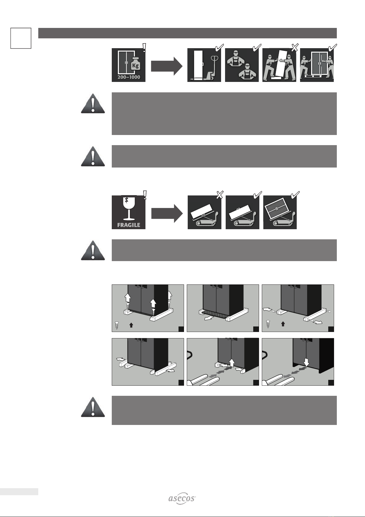
2. TRANSPORT ................................................................. 6
2.1. Tilting the cabinet .............................................. 6
2.2. Dismantling of the transport packaging ............................. 6
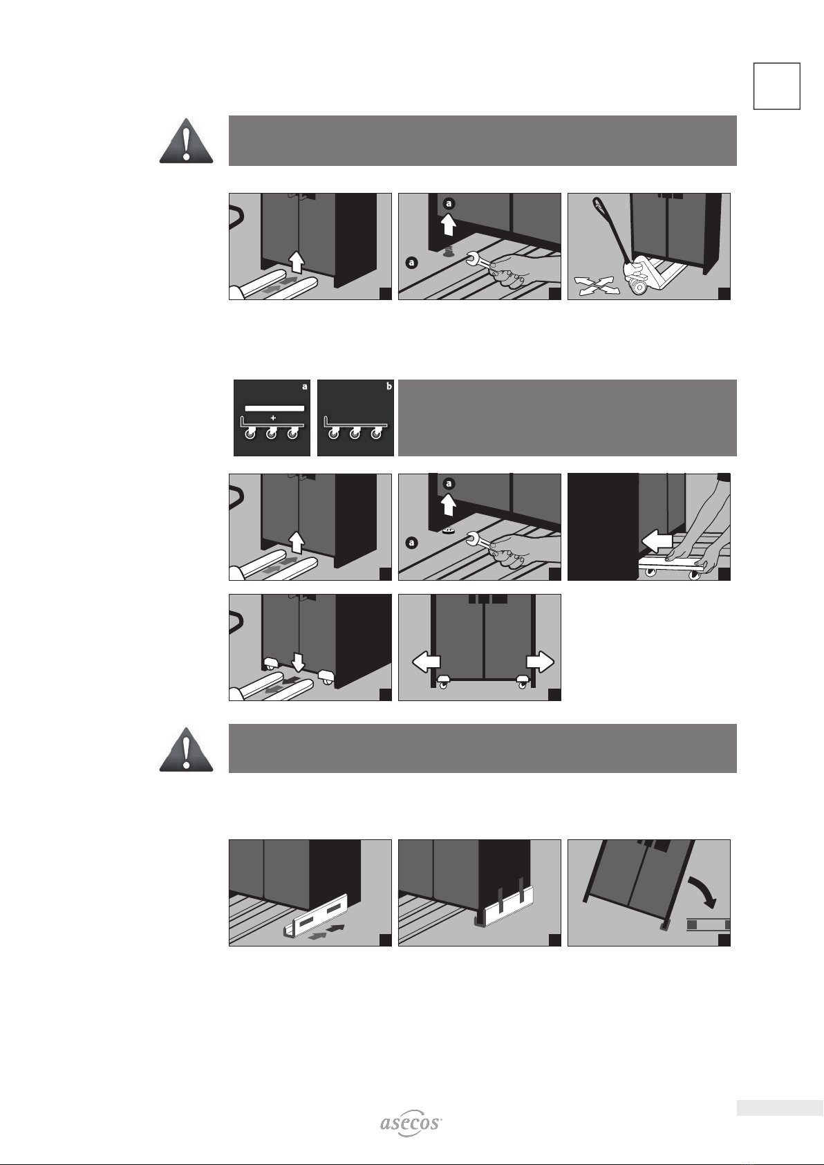
2.3. In-plant transport ............................................... 7
2.4. Q-Mover ...................................................... 7
2.5. Titling onto the side wall ......................................... 7
3. INSTALLATION ............................................................... 8
3.1. Alignment Of The Cabinets ....................................... 8
3.2. Commissioning ................................................. 8
4. CLOSING .................................................................... 8
4.1. In general ..................................................... 8
5. INTERIOR FITTINGS ........................................................... 9
5.1. Bottom collecting sump .......................................... 9
5.2. Grid shelves (height adjustable) ................................... 9
5.3. Shelves (height-adjustable) ...................................... 10
6. STORAGE .................................................................. 10
6.1. Notes on storage .............................................. 10
7. VENTILATION ................................................................11
7.1. Extraction unit (optional) ........................................11
8. BATTERY FIRE • EVENT OF FIRE • DISPOSAL .......................................11
8.1. Fire inside the cabinet (battery fire) ................................11
8.2. Opening the cabinet after the fire. . . . . . . . . . . . . . . . . . . . . . . . . . . . . . . . . 12
8.3. Disposal ..................................................... 12
9. SAFETY CHECKS ............................................................. 12
9.1. Contact ...................................................... 12
10. TECHNICAL DRAWING ........................................................ 13
11. TECHNICAL DATA ............................................................ 13
12. IO90.195.120.K2.WDC ........................................................ 14
12.1. Installation of the extraction unit (optional) ........................ 14
12.2. Connection to the power supply .................................. 14
12.3. Self-Test ...................................................... 15
12.4. Error during self-test ........................................... 15
12.5. Error and alarm overview. . . . . . . . . . . . . . . . . . . . . . . . . . . . . . . . . . . . . . . . 15
12.6. Potential-free alarm contact ..................................... 16
12.7. Warning/fire suppression system ................................. 16
12.8. Warning message .............................................. 17
12.9. Alarm stage 1 ................................................. 17
12.10. Alarm stage 2 ................................................. 18

5
EN
1. NOTES • GUIDELINES • GUARANTEE
1.1. GENERAL SAFETY NOTES
• When handling lithium-ion batteries, observe the applicable regulations and the information in these operating
instructions
• Work on the electrical system is to be carried out only with the power turned o and only byqualified electri-
cians – refer here to the regulations of the local electricity supply company.
• General damage to electronic components is to be repaired without delay by an asecos employee.
• Use only intact and undamaged mains cables for the battery charger
• Electrical protection in accordance with local standards must be provided by the customer (cabinets do not
have their own RCD circuit breaker or circuit breaker)
• The on-site installation conditions are to be observed.
• The instructions of the supervisory engineering department must be followed.
• Observe accident prevention regulations and workplace ordinance
•Ensure that the necessary safety checks are only carried out by authorised sta using original
spare parts
• Only use the cabinet after having been properly instructed; access is to be forbidden to unauthorised persons.
• The pivoting area of the doors is to be kept free at all times; doors are to be kept closed
• By assigning trained/authorised technical personnel you can prevent the malfunctions, damage and corrosion
damage that result from inappropriate transport.
• Observe the upper limits for stored quantities, loading etc.
• The following substances may not be stored in the cabinets with a fire suppression system: acids, alkalis,
magnesium, other metals (in powder form)
Set-up requirements
0–35 °C 30–70 %
1.2. GUARANTEE
The guarantee for this product is agreed between you (the customer) and your dealer (the seller). As the
manufacturer, asecos guarantees the products listed in the operating instructions for a period of 24 months
from the date of delivery. All model safety equipment are subject to a compulsory annual inspection by spe-
cialised sta authorised by the manufacturer. Otherwise the customer’s guarantee claim against the manufac-
turer expires.
1.3. CABINET DETAILS
Cabinet data: Logbook (included with the cabinet)
Technical drawing: Appenidix 1
Technical data: Table in Appendix 2
Model Lithium ion batteries
Storing Charging Extraction air system Fire supression unit Alarm system
BATTERY STORE
IO90.195.060.K1.WDC 4
IO90.195.120.K1.WDC 4
BATTERY STORE PRO
IO90.195.060.K2.WDC 444 4
BATTERY STORE & BATTERY STORE PRO
These models are used for passive storage (warehousing) of lithium-ion batteries. Passive storage involves
storing new or used lithium-ion batteries for a specified period of time

6
EN 2. TRANSPORT
CAUTION:
Transport the cabinet in an upright position on a pallet truck, tied and secured against slipping, until the
fi nal place of installation is reached.The transport locks in the door joints may only be removed directly
at the place of installation! Inappropriate transport can lead to concealed damage to the fi re protection
insulation!We can only guarantee the necessary quality if the cabinet is transported to the place of its use
by our specially trained sta .
ATTENTION:
The doors must be locked prior to transport! The extraction unit is inside the cabinet and is only mounted
after the in-plant transport to the place of use.
2.1. TILTING THE CABINET
CAUTION:
Tilting the cabinet may only be done without jolts!
2.2. DISMANTLING OF THE TRANSPORT PACKAGING
1
= 4×
2
= 8×
3
456
CAUTION:
Cabinets with a width of 600 mm: The clear entry width of the base is 520 mm.
Please note this when choosing your pallet truck!Devices with widths greater than the entry widths must
not be used.

7
EN
2.3. INPLANT TRANSPORT
• In-plant transport is also possible without transport locks (inserted as standard in the door joints)
ATTENTION:
The doors must be locked prior to transport! The optional extraction unit is inside the cabinet and is only
mounted after the in-plant transport to the place of use.
1
2
=4×
3
2.4. Q M O V E R
• Order no. 30037, available from your authorised dealer
a: upright transport
b: upright transport through standard doors (headroom 1986 ± 2mm)
12
=4×
3
4
5
CAUTION:
Written notifi cation of any damage to the cabinet must be given immediatly!
2.5. TITLING ONTO THE SIDE WALL
• Titling onto the side wall is only possible with the optionally available tilting bracket (order no. 29556).
123

8
EN 3. INSTALLATION
3.1. ALIGNMENT OF THE CABINETS
CAUTION:
Door elements must not scrape against the fi re prevention seals in the fold of the door when opening and
closing! Doors with an automatic closing mechanism must close automatically from every position and the
lock must be able to lock!
4×
2
max. 2× (!)
3
3.2. COMMISSIONING
• Before putting into operation for the fi rst time, the user must carry out an examination of the safety storage
cabinet for possible damage, such as defective or loose sealing elements, correct alignment and perfect func-
tioning of the door elements.
Use the cabinet and accessories only if they are in an orderly condition.
4. C L O S I N G
4.1. IN GENERAL
The doors are permanently self-closing.
The cabinets feature a cylinder lock with closing status indicator.
They can be integrated into a master key system.
ATTENTION:
The owner/user must ensure that all doors are kept closed whenever the contents of the cabinet are
not being accessed. In general, it must be noted that the cabinets do not possess an emergency unlocking
facility. This means that persons trapped inside the cabinet cannot free themselves!

9
EN
5. INTERIOR FITTINGS
5.1. BOTTOM COLLECTING SUMP
12
According to EN 14470-1: The bottom collecting sump must be
able to hold a minimum volume of 10 %of all the containers stored
in the cabinet [1] or at least 110 %of the volume of the largest single
container [2] , whichever of these volumes is larger.
Leaks:
• Liquid in the sump is to be collected using suitable means.
• The choice of means is your own responsibility.
123
5.2. GRID SHELVES HEIGHT ADJUSTABLE
2
3
4
5
6
7
8
9
Load capacity (kg/drum
platform)
IO90.195.120.K1.WDC / IO90.195.120.K2.WDC*
max. 180 kg
ATTENTION:
Model IO90.195.120.K2.WDC: The position of the fi re suppression device, smoke detector, thermal
sensor must not be changed when adjusting the height of the shelves.

10
EN 5.3. SHELVES HEIGHTADJUSTABLE
2
3
4
5
6
7
8
9
Load capacity (kg/drum
platform)
IO90.195.060.K1.WDC IO90.195.120.K1.WDC / IO90.195.120.K2.WDC*
max. 25 kg max. 75 kg max. 50 kg
Gilt bei
Special interior equipment:
Order No. 38516 / 38517
Order No. 38518 / 38519
ATTENTION:
Model IO90.195.120.K2.WDC: The position of the fi re suppression device, smoke detector, thermal
sensor must not be changed when adjusting the height of the shelves.
6. S T O R A G E
ATTENTION:
Never store obviously damaged lithium-ion batteries inside buildings.
Dispose of them without delay in disposal containers that are provided outside the building and approved
for transport.
6.1. NOTES ON STORAGE
Storage
• It is recommended to store new and used lithium-ion batteries separately (each on a di erent storage level)
in the safety storage cabinet.
Occupation of the storage levels (IO90.195.XXX.XX.WDC)
Grid shelves may be covered only up to 60% by battery chargers and batteries in order to ensure trouble-free
operation of the fi re suppression system and su cient air circulation.
ATTENTION:
Full-surface occupancy of the storage levels is not permitted.
IO90.195.120.K2.WDC:
The following substances must not be stored in the cabinets with fi re suppression system:Acids, bases,
magnesium, other metals (in powder form).
Li-Ion Li-Io
n
150 mm
CAUTION:
A distance of min. 150 mm must be maintained in the area in
front of the fi re suppression unit.

11
EN
7. VENTILATION
7.1. EXTRACTION UNIT OPTIONAL
• See point 10.1 for the installation.
The green indicator lamp signals that the fan is switched on.
ATTENTION:
Heat is generated during the charging of a lithium-ion battery !
Please note:
The technical ventilation (for the avoidance of heat accumulation in the interior) must run continuously.
A distance of at least 100 mm must be kept to the area of the fi re suppression unit.
8. BATTERY FIRE • EVENT OF FIRE • DISPOSAL
CAUTION
After a battery fi re and triggered fi re suppression device, the safety cabinet must be subjected to a thorough
inspection so that both fi re protection and CE conformity are maintained. For this purpose, the cabinet
must be handed over to the main factory of asecos GmbH in Gründau, where the specialist department
- depending on the degree of damage - makes an assessment of the economic e ciency and technical
possibilities of a repair. The customer then receives an o er of either a repair or a replacement, which can
be handed over to the responsible property insurer.
8.1. FIRE INSIDE THE CABINET BATTERY FIRE
NOTE for 2-door tall cabinets
Evacuation by at least 2 persons is recommended.
• For fast transport the cabinets are equipped with a transport base.
The cabinets are automatically disconnected from the mains supply in the case of transport.
CAUTION:
The doors must be locked before transport! Depending on the door heights, it may be necessary to remove
the ventilation attachment beforehand. Transport may only be carried out by qualifi ed personnel!
1
2
3
4
5

12
EN 8.2. OPENING THE CABINET AFTER THE FIRE
CAUTION:
Do not open the cabinet until it has cooled down. This is 6 times the fi re duration!
The cabinet may only be opened by authorised personnel (e.g. fi re brigade)!
Depending on the duration of the fi re, an ignitable vapour-air mixture may have formed, therefore remove
all ignition sources within a 10-metre radius around the cabinets before opening.
Use only non-sparking tools! Open the cabinets with extreme caution!
8.3. D I S P O S A L
The models can be disposed of once they have been dismantled and the materials sorted.
9. SAFETY CHECKS
As safety equipment the cabinets have to be checked for safety at least once per year. The next checking date
can be taken from the service sticker on the outside of the door. This annual check can be carried out with the
necessary care, and for securing your warranty claims in the case of fi re, only by an authorised asecos employ-
ee (refer also to our service brochure regarding this).
IO90.195.120.K2.WDC
A necessary service is automatically indicated by the cabinet by a fl ashing green LED. Within the context of
the annual check, the fi re suppression system, smoke detector and sensors will be checked in addition to the
check of all safety-related parts.
ATTENTION
In accordance with DIN 14676 the proper function of the smoke detector must be checked at least once
per year. In addition, we recommend the regular visual inspection of the battery chargers, batteries and
connecting cables.
9.1. C O N T A C T
The cabinets can be cleaned with a mild household cleaner and a soft cloth.
In case of damage please contact your dealer in order to have the cabinet repaired using original spare parts.
CONTACT:
In the case of defects or complaints about our products (within and also after the warranty period), and for
requesting safety checks or taking out a service contract, please contact our service hotline on:
Tel: +44 1785 22 70-90 info@asecos.co.uk

13
EN
10. TECHNICAL DRAWING
884
1166
156
156
(155)
1017
90°
90°
Fresh air
Exhaust air DN 75
Top view
290
1129
156
(155)
90°
Fresh air Exhaust air DN 75
Top view
884
1166
156
156
(155)
1017
90°
90°
Fresh air
Exhaust air DN 75
Top view
IO90.195.120.K1.WDC IO90.195.060.K1.WDC IO90.195.120.K2.WDC
11. TECHNICAL DATA
IO90.195.120.K1.WDC IO90.195.060.K1.WDC IO90.195.120.K2.WDC
Type 90 90 90
External dimensions W x D x H mm 1193 x 615 x 1953 599 x 615 x 1953 1193 x 615 x 1953
Internal dimensions W x D x H mm 1050 x 522 x 1647 450 x 522 x 1647 1050 x 522 x 1647
Weight without interior equipment kg 424 265 424
Distributed load kg/m² 531.00 894.00 531.00
Extraction air DN 75 75 75
Entry width transport base mm 1120 526 1120
Entry height transport base mm 90 90 90
Power consumption in operation W 1,5
Nominal voltage V 230
Frequency Hz 50/60

14
EN 12. IO90.195.120.K2.WDC
12.1. INSTALLATION OF THE EXTRACTION UNIT OPTIONAL
1
2
3
4
The extraction unit is for the avoidance of a heat accumulation in the interior during the charging process
inside the cabinet. The exhaust air from the cabinet is exhausted directly into the room. Connection to an
exhaust duct is not necessary.
12.2. CONNECTION TO THE POWER SUPPLY
Connections on the headpiece:
IO90.195.120.K2.WDC
IO90.195.120.K3.WDC
LED: Operating (green) RESET BUTTON LED: Error (red)
1 2 3
Mains connection for
extraction unit
Mains plug connector
Potential-free switch
contact
Connection to the power
supply
1
2
230 V
3

15
EN
12.3. S E L F T E S T
2
3
4
5
6b
12.4. ERROR DURING SELFTEST
1
2
5
3
5sec
4
5
ATTENTION:
After pressing the reset button, the self-test begins again. If the error persists, please contact the asecos
Service department.
12.5. ERROR AND ALARM OVERVIEW
EVENT LED GREEN LED red ACOUSTIC ALARM ACTIONS
Error during self-test o turned on 5 signal tones 1.) Restart with RESET button if error
persists: 2.) Contact Service
Service interval reached fl ashing o o Contact Service
Power failure o Flashes
every 20
seconds
3 short signal tones every 60
seconds
Check power supply
Warning message:
Temperature in the
cabinet >50 °C
o turned on Tone interval
(every 2 seconds for 250 ms)
see 10.8
Alarm stage 1:
Smoke detector detects
smoke in the cabinet
o turned on medium tone interval
(every 0.5 seconds for 250 ms)
see 10.9
Alarm stage 2:
Smoke detector detects
smoke in the cabinet,
Temperature in the
cabinet >70 °C
o fl ashing fast tone interval
(every 0.25 seconds for 125
ms)
see 10.10

16
EN 12.6. POTENTIALFREE ALARM CONTACT
NOTE:
The potential-free alarm contact is used to connect a signal to a control centre/control room. Direct
integration into a fi re alarm control panel (FACP) is not recommended or may only be carried out in consul-
tation with the person responsible for the system.
However, it is always recommended to connect the signal to a manned control centre/control
room!
The potential-free switching contact must always be connected by the customer (not a service).
(AC) / (DC)
(AC) / (DC)
Connector
Internal
alarm contact
Connection instructions
• Use only the supplied mating part (colour-coded black) to the plug for the connection
• The connection must be done by a qualifi ed electrician
• The contact is designed for a max. DC voltage of 30 V or a max. AC voltage of 230 V
• The maximum current load is 10 A
• The switch contact is normally closed!
• The switch contact opens as soon as mains voltage is present and no error is pending (device is „ready to
operate“)
12.7. WARNING/FIRE SUPPRESSION SYSTEM
• The warning/fi re suppression system o ers the option of connection to a constantly manned building man-
agement system or fi re alarm centre.
• Make use of this option so that trained rescue personnel can be quickly alerted and be on-site in a very short
time and, following an initial assessment of the situation, immediately initiate further measures (for example,
transporting the cabinet out of the building).
• In this way consequential damage to the building and personal injuries can be avoided.
• The extinguishing agent, based on potassium carbonate, is harmless in the necessary extinguishing agent
concentration and has no harmful e ects on the human organism.
• In case of triggering, the aerosol is ejected at a high temperature and temperatures of over 300 °C are briefl y
generated in front of and on the housing of the fi re suppression cartridge (according to the manufacturer‘s
data, a minimum distance to combustible materials need not be maintained; however, a distance of at least
150 mm to the fi re suppression cartridge should generally be maintained).
• After triggering of the fi re suppression cartridge, ventilate the room and the cabinet well, observing the instruc-
tions in point 8.
ATTENION:
The complete warning/fi re suppression system is active only with mains operation. The integrated smoke
detector is part of the entire fi re suppression system (direct power supply).

17
EN
12.8. WARNING MESSAGE
>50 °C
1
2
3
if connected
4
•Actions
Immediate visual inspection of the system by the company’s own qualified personnel.
Initiation of necessary actions.
If the interior temperature falls below 50 °C, the system returns to normal operation and the visual and acous-
tic signals are switched o.
12.9. ALARM STAGE 1
!
1
2
3
if connected
4
•Actions
Immediate visual inspection of the system by technical personnel (e.g. fire brigade).
Subsequently, initiation of necessary actions.
If the smoke detector does not detect any further smoke development in the cabinet, the system can be reset
to normal operation by briefly disconnecting the mains voltage.

18
EN 12.10. ALARM STAGE 2
>70 °C
1
2
3
if connected
4
5
6
7
• Actions
Immediate visual inspection of the system by technical personnel (e.g. fi re brigade).
Subsequently, initiation of necessary actions.
See 8.2 for the transport of the cabinets out of the building.
NOTE:
After the fi re suppression device has been triggered, the safety cabinet must be subjected to a thorough
inspection so that both fi re protection and CE conformity are maintained. For this purpose, the cabinet
must be handed over to the main factory of asecos GmbH in Gründau, where the specialist department -
depending on the degree of damage - will make an assessment of the economic e ciency and technical
possibilities of a repair. The customer then receives an o er of either a repair or a replacement, which can
be handed over to the responsible property insurer.

19
EN

asecos GmbH
Sicherheit und Umweltschutz
Weiherfeldsiedlung 16–18
DE-63584 Gründau
+49 6051 92200
+49 6051 922010
asecos Ltd.
Safety and Environmental Protection
Profile House
Stores Road
Derby, Derbyshire
DE21 4BD
+44 1332 415933
asecos S.L.
Seguridad y Protección del
Medio Ambiente
CIM Vallès, C/ Calderí S/N
Oficinas 75 a 77
ES-08130 - Santa Perpètua de Mogoda
Barcelona
+34 935 745911
+34 935 745912
asecos bv
Veiligheid en milieubescherming
Tuinderij 15
NL-2451 GG Leimuiden
+31 172 506476
+31 172 506541
asecos
Safety and Environmental Protection Inc.
19109 West Catawba Avenue, Suite 200
Cornelius, NC 28031
USA
+1 704 8973820
+49 6051 922010
asecos Schweiz AG
Sicherheit und Umweltschutz
Gewerbe Brunnmatt 5
CH-6264 Pfanau
+41 62 754 04 57
+41 62 754 04 58
asecos SARL
Sécurité et protection de l’environnement
1, rue Pierre Simon de Laplace
FR-57070 Metz
+33 3 87 78 62 80
This manual suits for next models
4
Table of contents
Other asecos Storage manuals

asecos
asecos Q-LINE Q15 User manual

asecos
asecos UB-S-90 User manual

asecos
asecos Q Series User manual

asecos
asecos V-CLASSIC-90 User manual

asecos
asecos FX Series User manual

asecos
asecos ION BATTERY STORE User manual

asecos
asecos V Series User manual

asecos
asecos FX Series User manual

asecos
asecos G-CLASSIC-30 User manual

asecos
asecos ION-CLASSIC-90 User manual
Popular Storage manuals by other brands

HAFENBANDE
HAFENBANDE Twin Door Assembly instructions

Toshiba
Toshiba CANVIO CONNECT II 2.5" user manual

Maxtor
Maxtor Basics ATA/100 datasheet

Freecom
Freecom ValueLoader DLT VS80 Installation and operation guide

Synology
Synology FlashStation FS3017 Hardware installation guide

NI
NI CF-6004 USER GUIDE AND SPECIFICATIONS