asecos V-CLASSIC-90 User manual

EN
EP.V.35384.00 | 04.2023
DE
USER MANUAL
Safety storage cabinets according to EN14470-1
BEDIENUNGSANLEITUNG
Sicherheitsschränke nach EN14470-1
Jahre10
Garantie*
10 JAHRE GARANTIE
Bei jährlicher Beauftragung des
Premium-Tarifs verlängert sich die
Garantie für Ihren V-LINE Sicherheits-
schrank (Typ 90) auf bis zu 10 Jahre.
Years10
Warranty*
10 YEARS WARRANTY
Upon conclusion of an asecos
service and maintenance agreement
(PREMIUM tari), you will get a
warranty extension for up to 10 years
for your V-LINE safety storage cabinet.

V90.196.060.MV.2VD:0012
V-CLASSIC-90

Contact
Company
Street
Name of contact person
email
Serial numbers of safety storage cabinets
Phone No.
Postal code Town
YOUR PERSONAL DOCUMENTATION TO THE asecos
SAFETY CABINET
Dear Customer,
you have made a decisive investment in safety for your company by purchasing this asecos safety
storage cabinet. You now own an innovative product made of top-quality materials guaranteeing
the highest quality standards.
asecos safety storage cabinets have complete authorisation documents. We archive the authori-
sation documents for every individual cabinet, keeping them ready for you should you ever need
them (e.g. for a works inspection or similar). Simply request them using this form.
Tear of or copy that page and return to us by fax with your address and serial number of the
cabinet on it.
Yours sincerely
asecos GmbH
asecos GmbH
Customer service
Weiherfeldsiedlung 16–18
D-63584 Gründau
Fax: +49 60 51 - 92 20-10
email: service asecos.com

4
EN
OPERATING INSTRUCTIONS
Dear customer,
Thank you very much for purchasing a safety storage cabinet from our company, with which you have made
a decisive investment in the safety within your company. Our safety storage cabinets make the storage of
hazardous materials at the workplace safe and convenient for you.
Please read these operating instructions very carefully. Get to know the advantages and simple operability of
our safety storage cabinets in detail. This simplifies the daily handling of hazardous materials for you.
Many thanks
Your asecos team
1. NOTES • GUIDELINES • GUARANTEE ...........................................5
1.1. General safety notes ............................................... 5
1.2. Guarantee........................................................ 5
1.3. Cabinet Details.................................................... 5
2. TRANSPORT ...............................................................6
2.1. Tilting the cabinet ................................................. 6
2.2. Dismantling of the transport packaging................................. 6
2.3. In-plant transport .................................................. 7
3. ERECTION • COMMISSIONING • FUNCTION......................................7
3.1. Commissioning.................................................... 7
3.2. Alignment Of The Cabinets .......................................... 7
4. CLOSING ..................................................................8
5. SURCHARGE TOPMOUNTED CABINET ........................................8
5.1. Assembly of the attached cabinet ..................................... 9
6. INTERIOR FITTINGS .........................................................9
6.1. Bottom collecting sump............................................. 9
6.2. Tray shelves (height-adjustable) ...................................... 9
6.3. Tray shelf with storage box ......................................... 10
7. STORAGE. . . . . . . . . . . . . . . . . . . . . . . . . . . . . . . . . . . . . . . . . . . . . . . . . . . . . . . . . . . . . . . . .10
8. EARTHING................................................................10
8.1. Ground connection ............................................... 10
9. VENTILATION .............................................................11
10. FIRE • DISPOSAL. . . . . . . . . . . . . . . . . . . . . . . . . . . . . . . . . . . . . . . . . . . . . . . . . . . . . . . . . . .12
10.1. Opening the cabinet after the fire.................................... 12
10.2. Disposal ........................................................ 12
11. S AF E T Y C H EC K S ...........................................................12
11.1. In general ....................................................... 12
11.2. Wearing parts .................................................... 12
12. TECHNICAL DRAWING......................................................13
13. TECHNICAL DATA ..........................................................13
13.1. Table with technical data ........................................... 13
13.2. Table with storage capacities........................................ 13

5
EN
1. NOTES • GUIDELINES • GUARANTEE
1.1. GENERAL SAFETY NOTES
• Observe applicable statutes and regulations, and the notes in these operating instructions, when handling
hazardous materials
• Work on the electrical system is to be carried out only with the power turned o and only byqualified electri-
cians – refer here to the regulations of the local electricity supply company.
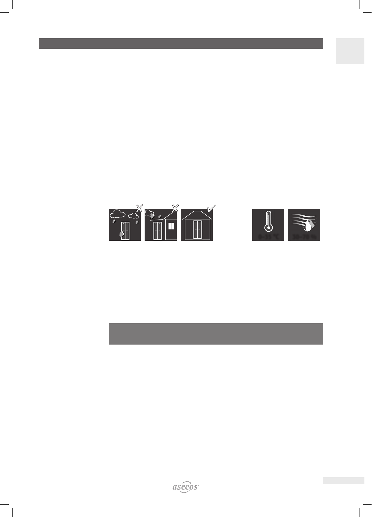
• The on-site installation conditions are to be observed (e.g. bolting the cabinets to the building).
• The instructions of the supervisory engineering department must be followed.
• Observe accident prevention regulations and workplace ordinance
• Ensure that the necessary safety checks are only carried out by authorised sta using original
spare parts
• Only use the cabinet after having been properly instructed; access is to be forbidden to unauthorised persons.
• The pivoting area of the doors is to be kept free at all times; doors/drawers are to be kept closed
• By assigning trained/authorised technical personnel you can prevent the malfunctions, damage and corrosion
damage that result from inappropriate transport.
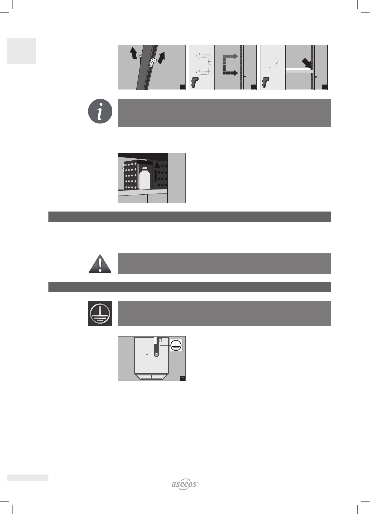
• Observe the upper limits for stored quantities, loading etc.
• Containers with a volume larger than that of the bottom collecting sump may not be placed inside the cabi-
net; spilt hazardous materials are to be collected immediately and removed
• The cabinet is used exclusively for the storage of hazardous substances. Other activities in the cabinet, e.g.
decanting, removal from containers, cleaning of containers, sampling, must not be carried out. The placed,
mobile containers must not show any wetting / contamination on the outside.
• Before storing such materials, check that the cabinet’s surface is resistant to the chemicals.
• Before the initial commissioning, the safety storage cabinet is to be examined by the user for possible dam-
age.
Set-up requirements
0–35 °C
30–70 %
1.2. GUARANTEE
The guarantee for this product is agreed between you (the customer) and your dealer (the seller). As the
manufacturer, asecos guarantees the products listed in the operating instructions for a period of 24 months
from the date of delivery. All model safety equipment are subject to a compulsory annual inspection by spe-
cialised sta authorised by the manufacturer. Otherwise the customer’s guarantee claim against the manufac-
turer expires.
1.3. CABINET DETAILS
A complete overview of the models can be found at the start of the operating instructions.
Development: asecos GmbH Sicherheit und Umweltschutz, D-63584 Gründau.
Cabinet data: logbook (included with the cabinet)
Technical drawing: see appenidix
Technical data: table in appendix
V-CLASSIC-90
This model is tested, certified and marked according to requirements of EN 14470-1. It is intended for the
storage of flammable liquids and toxic and aggressive hazardous materialsin work rooms in accordance with
the valid national regulations.

6
EN
2. TRANSPORT
CAUTION:
Transport the cabinet in an upright position on a pallet truck, tied and secured against slipping, until the
final place of installation is reached.The transport locks in the door joints may only be removed directly
at the place of installation! Inappropriate transport can lead to concealed damage to the fire protection
insulation!We can only guarantee the necessary quality if the cabinet is transported to the place of its use
by our specially trained sta.
CAUTION:
The cabinet must not be moved by pulling the opened drawer! Pulling or sliding may only be carried out in
the body housing!
2.1. TILTING THE CABINET
2.2. DISMANTLING OF THE TRANSPORT PACKAGING
2×
2
2×
3
4×
4
5a
5b
5c
5×
6

7
EN
2.3. INPLANT TRANSPORT
CAUTION:
The cabinet must not be moved by pulling the opened drawer! Pulling or sliding may only be carried out in
the body housing!
M10
Steps for manoeuvring the cabinet:
• Open the drawer of the cabinet
• Connect the belts with steel angles or steel rings using a screw M10
• Screw the steel angles/rings into the threaded insert in the base of the
cabinet
• Move the cabinet carefully using the belts
3. ERECTION • COMMISSIONING • FUNCTION
3.1. COMMISSIONING
• Before putting into operation for the first time, the user must carry out an examination of the safety storage
cabinet for possible damage, such as defective or loose sealing elements, correct alignment and perfect func-
tioning of the door elements.
Use the cabinet and accessories only if they are in an orderly condition.
3.2. ALIGNMENT OF THE CABINETS
After opening the drawer, the cabinet can be aligned using the integrated adjusting aids.
2× 3×
1
23
4

8
EN
4. CLOSING
123
Standard operation:
vertical drawers must be
opened and closed manually
Event of fire: Thermal
release, open vertical
drawers close automat-
ically
5. SURCHARGE TOPMOUNTED CABINET
The V-LINE safety storage cabinets can be loaded if the cabinet
was ordered with article HF.L.34938 (order no. 40405). These
cabinets are then structurally adjusted at the factory and
additionally marked on the outside as load-bearing.
A
C
D
B
A C C
C
BDD
head section rear
head section front
magnetic tape
fixation points for screw M6
CAUTION:
Only the fixation points [D] shown in the
drawing must be used!
Other fixation points or fixation types
(e.g. silicone) are not permitted!
• The magnetic tape mounted on the headboard serves as a support surface for the top cabinet and can be cut
to size if required.
CAUTION:
The magnetic tape may only be attached to the rear head section!

9
EN
5.1. ASSEMBLY OF THE ATTACHED CABINET
490 mm
65 mm
1
b
a
b= 490 mm
a= Ø 7 mm
c= 65 mm
c
2
3
= M6
4
5
6. INTERIOR FITTINGS
6.1. BOTTOM COLLECTING SUMP
11
22
According to EN 14470-1: The bottom collecting sump must be
able to hold a minimum volume of 10 %of all the containers stored
in the cabinet [1] or at least 110 %of the volume of the largest single
container [2] , whichever of these volumes is larger.
Use as a storage surface in case of cabinets with several storage levels:
8
8
4
4
4
4
4
CAUTION:
Use as a storage surface is possible only in conjunction with a perfo-
rated metal plate insert.
Leaks:
• Liquid in the sump is to be collected using suitable means.
123
6.2. TRAY SHELVES HEIGHTADJUSTABLE
1
2×
23

10
EN
4×
4
4×
5
2×
6
NOTE
The tray floor is also available as a separating floor. With side seals, it oers the possibility of separate
storage of dierent hazardous substances within the vertical drawer. It is also height-adjustable without
tools.
6.3. TRAY SHELF WITH STORAGE BOX
The storage box is used for storing hazardous substances that are to be
kept separately under lock and key in the cabinet. The storage box is
factory-fitted in the left-hand vertical drawer in the uppermost position
in conjunction with the tray base and firmly screwed to the frame of the
vertical drawer.
7. STORAGE
• The storage of corrosive liquids can aect the function of the shut-o equipment for the air supply and
exhaust.
• Each container placed inside reduces the minimum containment volume in relation to the total stored quan-
tity.
Applicable for all models: Depending on the type class of the cabinet, observe therespective valid national
regulations!
8. EARTHING
An earth connection may be necessary, depending on the customer-specific use of the safety storage
cabinet. The decision regarding this is taken on the basis of a risk analysis by the customer.
8.1. GROUND CONNECTION
All models have an earthing connection. The cabinet body (side and top panels) is metallically conductively
connected to each other via the earthing connection. The earthing connection is prepared for the creation of
the potential equalisation on site. It is enclosed with the product and must be mounted on site at the appro-
priate location on the headboard

11
EN
A
B
B
B
B
C
C
D
D
E
F
G
F
Legende
A1 × screw M6×30
B4 × washer Ø 6,4
C2 × spring washer Ø 6,4
D2 × serrated lock washer Ø 6,4
E1 × nut with clamping part
Fearthing wire with ring cable lug (on-site
connection)
Gmetal part of the safety storage cabinet
9. VENTILATION
CAUTION
The fire protection valves near the supply and extraction air connections are safety and
maintenance-relevant components.
In order to check the correct operation or to replace a defective element, please ensure that flexible
connecting hoses or sliding pieces are used to connect to an extraction system in order to ensure simple
dismounting and re-mounting of the extraction air connection.
• All models can be connected to a technical exhaust system via the exhaust connector. Please see the respec-
tively applicable national regulations for the specified air recirculation rate, maximum pressure losses and
exhaust air ducts.
• If installed on an exhaust system, a check must be carried out to ensure proper connection to the system (e.g.
using a smoke tube)

12
EN
10. FIRE • DISPOSAL
10.1. OPENING THE CABINET AFTER THE FIRE
CAUTION:
Depending upon the duration of the fire an ignitable vapour/air mixture may have formed; therefore remove
all sources of ignition within a 10 metre radius of the cabinet before opening it.
- use only spark-free tools
- open the cabinets with extreme caution
10.2. DISPOSAL
The models can be disposed of once they have been dismantled and the materials sorted.
11. SAFETY CHECKS
11.1. IN GENERAL
As safety equipment the cabinets have to be checked for safety at least once per year. The next checking date
can be taken from the service sticker on the outside of the door. This annual check can be carried out with the
necessary care, and for securing your warranty claims in the case of fire, only by an authorised asecos employ-
ee (refer also to our service brochure regarding this).
In addition, we recommend that you carry out a daily and monthly functional check:
Daily functional check
• applies to the spill containment sumps (collect and remove any leakages)
Monthly functional check
• perfect function of the drawers
• correct seating and condition of the fire protection seals
Case of damage
In case of damage please contact your dealer in order to have the cabinet repaired using original spare parts.
The cabinets can be cleaned with a mild household cleaner and a soft cloth.
11.2. WEARING PARTS
Various safety-related components of the safety storage cabinet are wearing parts and must be replaced at
regular intervals by asecos Service. A list of the parts aected for your safety cabinet is available on request
from [email protected].
CONTACT:
In the case of defects or complaints about our products (within and also after the warranty period), and for
requesting safety checks or taking out a service contract, please contact our service hotline on:
Tel: +44 1785 22 70-90 info@asecos.co.uk

13
EN
130
399
860
Exhaust air DN 75
Earthing link
Fresh air
V90.196.060.MV.2VD:0012
12. TECHNICAL DRAWING
13. TECHNICAL DATA
13.1. TABLE WITH TECHNICAL DATA
Key for “Technical data” table
1Dimensions W x D x H external 5Maximum load (kg)
2Internal dimensions W x D x H 6Distributed load (kg/m²)
3type 7Volume with 30 times air change (m³/h)
4Weight of empty cabinet(kg) 8Dierential pressure (10 times air change EK5/AK4) (Pa)
V-LINE | V-CLASSIC-90
1 2 3 4 5 6 7 8
V90.196.060.MV.2VD:0012 90 420 100 556 20 11
13.2. TABLE WITH STORAGE CAPACITIES
Legend for “Storage capacities” table
Load capacity (kg) of storage levels Retention capacity (ltr.) Maximum container volume in the
cabinet (ltr.)
V-LINE | V-CLASSIC-90
Interior equipment 1tray shelf 2perforated insert 3bottom collecting sump
1 2 3 1 3 3
V90.196.060.MV.2VD:0012 30 30 30 4,2 11,5 10,45

14
DE
BEDIENUNGSANLEITUNG
Sehr geehrte Kundin, sehr geehrter Kunde,
vielen Dank für den Kauf eines Sicherheitsschrankes aus unserem Haus, mit dem Sie eine entscheidende
Investition für die Sicherheit in Ihrem Haus getätigt haben. Mit unseren Sicherheitsschränken wird für Sie die
Lagerung von Gefahrstoen am Arbeitsplatz sicher und komfortabel.
Lesen Sie diese Bedienungsanleitung sehr sorgfältig. Lernen Sie die Vorteile und einfache Bedienbarkeit un-
serer Sicherheitsschränke im Detail kennen. Dies vereinfacht für Sie den täglichen Umgang mit Gefahrstoen.
Vielen Dank
Ihr asecos-Team
1. HINWEISE • RICHTLINIEN • GEWÄHRLEISTUNG .................................15
1.1. Allgemeine sicherheitstechnische Hinweise ............................ 15
1.2. Gewährleistung .................................................. 15
1.3. Schrankdetails ................................................... 15
2. TRANSPORT ..............................................................16
2.1. Umlegen des Schrankes ........................................... 16
2.2. Demontage Transportverpackung .................................... 16
2.3. Rangieren des Schrankes........................................... 17
3. AUFSTELLUNG • INBETRIEBNAHME • FUNKTION ................................17
3.1. Inbetriebnahme .................................................. 17
3.2. Ausrichten der Schränke ........................................... 17
4. SCHLIESSUNG. . . . . . . . . . . . . . . . . . . . . . . . . . . . . . . . . . . . . . . . . . . . . . . . . . . . . . . . . . . . .18
5. AUFLAST SCHRANKAUFSATZ ...............................................18
5.1. Montage des Aufsatzschranks ....................................... 19
6. INNENAUSSTATTUNG ......................................................19
6.1. Bodenauffangwanne .............................................. 19
6.2. Wannenböden (höhenverstellbar). . . . . . . . . . . . . . . . . . . . . . . . . . . . . . . . . . . . 19
6.3. Wannenboden mit Lagerbox ........................................ 20
7. LAGERUNG ...............................................................20
8. ERDUNG .................................................................20
8.1. Erdungsanschluss................................................. 20
9. LÜFTUNG. . . . . . . . . . . . . . . . . . . . . . . . . . . . . . . . . . . . . . . . . . . . . . . . . . . . . . . . . . . . . . . . .21
10. BRANDFALL • ENTSORGUNG.................................................22
10.1. Öffnen des Schrankes nach dem Brand ...............................22
10.2. Entsorgung ......................................................22
11. SICHERHEITSTECHNISCHE ÜBERPRÜFUNG.....................................22
11.1. Allgemein ....................................................... 22
11.2. Verschleißteile ...................................................22
12. TECHNISCHE ZEICHNUNG ..................................................23
13. TECHNISCHE DATEN .......................................................23
13.1. Tabelle Technische Daten .......................................... 23
13.2. Tabelle Lagerkapazitäten ...........................................23

15
DE
1. HINWEISE • RICHTLINIEN • GEWÄHRLEISTUNG
1.1. ALLGEMEINE SICHERHEITSTECHNISCHE HINWEISE
• Beachten Sie die für den Umgang mit Gefahrstoen anzuwendenden Gesetze und Vorschriften und die
Hinweise dieser Bedienungsanleitung.
• Arbeiten an der elektrischen Anlage sind im stromlosen Zustand und durch Elektrofachkräfte auszuführen –
siehe hierzu auch die zutreende Unfallverhütungsvorschrift, die VDE-Vorschriften und die Regelungen des
örtlichen Energieversorgers.
• Bauseitige Aufstellbedingungen sind zu beachten (z.B. Verschrauben der Schränke mit Gebäude).
• Den Anweisungen des Technischen Aufsichtsdienstes ist Folge zu leisten.
• Beachten Sie die Unfallverhütungsvorschriften und die Arbeitsstättenrichtlinie.
• Stellen Sie die geforderten sicherheitstechnischen Überprüfungen nur durch autorisiertes Fachpersonal
unter Verwendung von Originalersatzteilen sicher.
• Benutzen Sie den Schrank nur nach Einweisung, Unbefugten ist der Zugri zu untersagen.
• Der Schwenkbereich der Türen ist stets freizuhalten, Türen/Schubladen sind geschlossen zu halten
• Durch geschultes/autorisiertes Fachpersonal verhindern Sie Fehlfunktionen, Beschädigungen und Korrosions-
schäden, die durch einen unsachgemäßen Transport entstehen können.
• Beachten Sie die Höchstgrenzen für Lagermengen, Belastungen, etc.
• Es dürfen keine größeren Gefäße eingestellt werden, als das Volumen der Bodenauangwanne fassen kann,
austretende Gefahrstoe sind sofort aufzunehmen und zu entfernen
• Der Schrank dient ausschließlich zur Lagerung von Gefahrstoen. Andere Tätigkeiten im Schrank wie z.B.
Umfüllen, Entnahme aus Behältern, Reinigen von Behältern, Probenahme dürfen nicht durchgeführt werden.
Die eingestellten, ortsbeweglichen Behälter dürfen an der Außenseite keine Benetzungen / Kontaminationen
aufweisen.
• Überprüfen Sie vor der Nutzung/Einlagerung die Beständigkeit der Schrankoberfläche / Inneneinrichtungs-
komponenten gegen die Chemikalie.
• Vor der ersten Inbetriebnahme ist der Sicherheitsschrank vom Nutzer auf eventuelle Schäden zu untersuchen.
Aufstell- und Umgebungsbedingungen
0–35 °C
30–70 %
1.2. GEWÄHRLEISTUNG
Die Gewährleistung für dieses Produkt wird zwischen Ihnen (dem Kunden) und Ihrem Fachhändler (dem Ver-
käufer) vereinbart. asecos übernimmt als Hersteller für die in der Bedienungsanleitung aufgeführten Produkte
eine Gewährleistung von 24 Monaten ab Lieferdatum. Alle Modelle unterliegen, als sicherheitstechnische
Einrichtung, einer jährlichen Überprüfungspflicht durch vom Hersteller autorisiertes Fachpersonal. Andernfalls
erlischt der Gewährleistungsanspruch des Kunden gegenüber dem Hersteller.
1.3. SCHRANKDETAILS
Eine komplette Modellübersicht finden Sie am Anfang der Bedienungsanleitung.
Hersteller ist die asecos GmbH Sicherheit und Umweltschutz, D-63584 Gründau.
Schrankdaten: Bordbuch (liegt dem Schrank bei)
Technische Zeichnung: Anhang
Technische Daten: Tabelle im Anhang
V-CLASSIC-90
Diese Modelle sind nach Anforderungen der DIN EN 14470-1 geprüft, zertifiziert und gekennzeichnet. Sie die-
nen der vorschriftsmäßigen Lagerung von entzündbaren Flüssigkeiten und aggressiver und giftiger Gefahrstoe
in Arbeitsräumen gemäß den gültigen nationalen Regelungen.

16
DE
2. TRANSPORT
ACHTUNG:
Transportieren Sie den Schrank mit einem Hubwagen stehend, verschnürt und rutschgesichert bis zum
endgültigen Aufstellort.
Die Transportsicherungen in den Türfugen dürfen erst direkt am Aufstellort entfernt werden! Unsachge-
mäßer Transport kann zu verdeckten Schäden an der Brandschutzisolierung führen!
Wir können die notwendige Qualität nur gewährleisten, wenn der Schrank durch unser speziell ausgebil-
detes Fachpersonal an die Verwendungsstelle transportiert wird.
ACHTUNG:
Eine Kraftausübung an dem Auszug ist weder im geöneten noch im geschlossenen Zustand erlaubt!
2.1. UMLEGEN DES SCHRANKES
2.2. DEMONTAGE TRANSPORTVERPACKUNG
2×
2
2×
3
4×
4
5a
5b
5c
5×
6

17
DE
2.3. RANGIEREN DES SCHRANKES
ACHTUNG:
Eine Kraftausübung an dem Auszug ist weder im geöneten noch im geschlossenen Zustand erlaubt!
M10
Schritte zum Rangieren des Schranks:
• Auszug des Schranks önen
• Gurte an Stahlwinkel oder Stahlösen mit Schraube M10 befestigen
• Stahlwinkel/Stahlösen in die Rampa-Mue im Fußteil des Schranks
schrauben
• Schrank vorsichtig an den Gurten Rangieren
3. AUFSTELLUNG • INBETRIEBNAHME • FUNKTION
3.1. INBETRIEBNAHME
Vor der ersten Inbetriebnahme ist der Sicherheitsschrank vom Nutzer auf evtl. Beschädigungen wie defekte
oder abgelöste Dichtungselemente, korrekte Ausrichtung und einwandfreie Funktion der Türelemente (Schar-
niere, Verriegelungssysteme, evtl. Türschließer und Türfeststellanlage) zu untersuchen.
Benutzen Sie den Schrank und das Zubehör nur in ordnungsgemäßem Zustand.
3.2. AUSRICHTEN DER SCHRÄNKE
Der Schrank kann bei geönetem Auszug im vorderen Bereich an den integrierten Justierhilfen ausgerichtet
werden.
2× 3×
123
4

18
DE
4. SCHLIESSUNG
123
Normalbetrieb: Vertika-
lauszüge mit Hand önen
und schließen
Brandfall: Thermoaus-
lösung, oenstehende
Vertikalauszüge schließen
automatisch
5. AUFLAST SCHRANKAUFSATZ
Die V-LINE Sicherheitsschränke sind auflastfähig, sofern der
Schrank mit Artikel HF.L.34938 (Best.-Nr. 40405) bestellt
wurde. Dies Schränke sind dann werkseitig konstruktiv angepasst
und außen zusätzlich als auflastfähig gekennzeichnet.
A
C
D
B
A C C
C
BDD
Kopfteil hinten
Kopfteil vorn
Magnetband
Befestigungspunkte für
Schraube M6
ACHTUNG:
Es sind ausschließlich die in der
Zeichnung dargestellten Befestigungs-
punkte [D] für den Aufsatzschrank zu
benutzen! Andere Befestigungspunkte
oder Befestigungsarten (z.B. Silikon)
sind ausdrücklich nicht zulässig.
• Das auf dem Kopfteil montierte Magnetband dient als Auflagefläche für den Aufsatzschrank und kann bei
Bedarf zugeschnitten werden.
ACHTUNG:
Das Magnetband darf nur auf dem hinteren Kopfteil angebracht werden!

19
DE
5.1. MONTAGE DES AUFSATZSCHRANKS
490 mm
65 mm
1
b
a
b= 490 mm
a= Ø 7 mm
c= 65 mm
c
2
3
= M6
4
5
6. INNENAUSSTATTUNG
6.1. BODENAUFFANGWANNE
11
22
Gemäß EN 14470-1: Die Bodenwanne muss ein Mindestauangvo-
lumen von 10 % aller im Schrank gelagerten Gefäße[1]haben, oder
mindestens 110 % des Volumens des größten Einzelgebindes[2], je
nachdem welches Volumen größer ist.
Nutzung als Stellfläche bei Schränken mit mehreren Lagerebenen:
8
8
4
4
4
4
4
ACHTUNG:
Eine Nutzung der Bodenauangwanne als Stellfläche ist nur in
Verbindung mit einem Locheinsatz zulässig.
Leckage:
• Flüssigkeit in der Auangwanne ist mit geeigneten Mitteln aufzunehmen.
123
6.2. WANNENBÖDEN HÖHENVERSTELLBAR
1
2×
23

20
DE
4×
4
4×
5
2×
6
HINWEIS
Der Wannenboden ist auch als Trennboden erhältlich. Mit seitlichen Dichtungen bietet er die Möglichkeit
der getrennten Lagerung unterschiedlicher Gefahrstoe innerhalb vom Vertikalauszug. Er ist ebenso
werkzeugfrei höhenverstellbar.
6.3. WANNENBODEN MIT LAGERBOX
Die Lagerbox dient zur Lagerung von Gefahrstoen die im Schrank
separat unter Verschluss gehalten werden sollen. Die Lagerbox ist in
Verbindung mit dem Wannenboden werkseitig im linken Vertikalauszug
an oberster Position eingebaut und fest mit dem Rahmen vom Vertikal-
auszug verschraubt.
7. LAGERUNG
• Eingelagerte korrosive Flüssigkeiten können die Funktion der Absperrvorrichtungen der Zu- u. Abluft beein-
trächtigen.
• Jedes eingestellte Gebinde reduziert das geforderte Mindestauangvolumen im Verhältnis zur Gesamtlager-
menge.
Für alle Modelle gilt: Beachten Sie in Abhängigkeit der Typklasse des Schrankes die entsprechenden
gültigen nationalen Regelungen!
8. ERDUNG
Je nach kundenspezifischer Nutzung des Sicherheitsschrankes kann ein Erdungsanschluss erforderlich sein.
Die Entscheidung darüber wird durch eine kundenseitige Gefährdungsbeurteilung getroen.
8.1. ERDUNGSANSCHLUSS
Alle Modelle verfügen über einen Erdungsanschluss. Über den Erdungsanschluss ist der Schrankkorpus
(Seiten- und Dachbleche) metallisch leitend miteinander verbunden. Der Erdungsanschluss ist vorbereitet
zur Herstellung des bauseitigen Potentialausgleichs, ist dem Produkt beigelegt und muss vor Ort an entspre-
chender Stelle auf dem Kopfteil montiert werden
Table of contents
Languages:
Other asecos Storage manuals

asecos
asecos FX Series User manual

asecos
asecos Q Series User manual

asecos
asecos Q-LINE Q15 User manual

asecos
asecos F Series User manual

asecos
asecos G-CLASSIC-30 User manual

asecos
asecos FX Series User manual

asecos
asecos BATTERY CHARGE User manual

asecos
asecos ION BATTERY STORE User manual

asecos
asecos ION-CLASSIC-90 User manual

asecos
asecos UB-S-90 User manual