Installation and Maintenance Instructions for
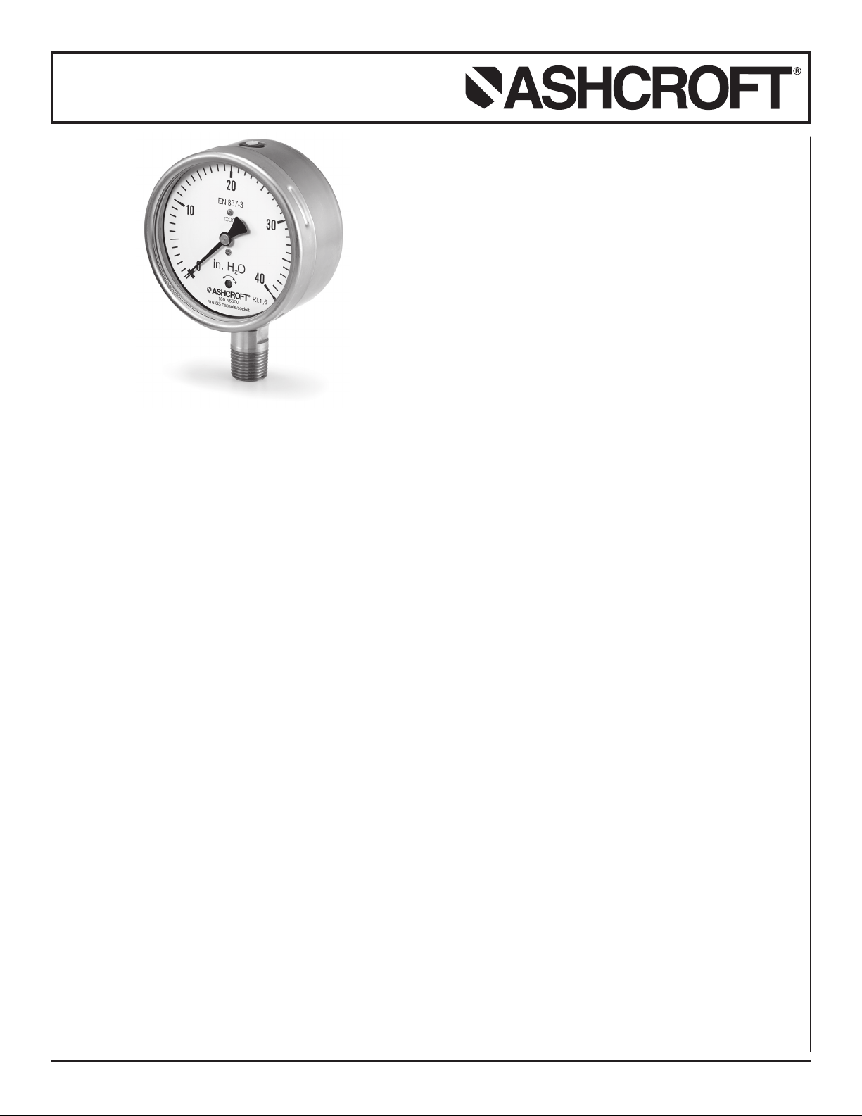
N5500 Capsule Pressure Gauges
© Ashcroft Inc. 2019, 250 East Main Street, Stratford, CT 06614-5145, USA, Tel: 203-378-8281, Fax: 203-385-0357, www.ashcroft.com
All sales subject to standard terms and conditions of sale. n5500_gauge_im_RevA_03-10-21 1
1 INTRODUCTION................................................................... 1
2SAFETY................................................................................. 1
2.1 General sources of hazards......................................... 1
2.2 Use in accordance with intended purpose ................ 1
2.3 Operator’s responsibility.............................................. 1
2.4 Operator qualifications ................................................ 2
2.5 Signs/Safety markings................................................. 2
2.6 Safety equipment.......................................................... 2
3 TECHNICAL DATA ............................................................... 2
4 CONSTRUCTION AND FUNCTION..................................... 2
4.1 Overview........................................................................ 2
4.2 Description of function ................................................ 2
4.3 Description of components......................................... 2
4.2 Accessories................................................................... 2
5TRANSPORT ........................................................................ 2
5.1 Safety............................................................................. 2
5.2 Transport inspection .................................................... 2
5.3 Storage .......................................................................... 2
6ASSEMBLY/INSTALLATION ................................................ 2
6.1 Safety............................................................................. 2
6.2 Installation..................................................................... 3
6.3 Start Up ......................................................................... 3
6.4 Zero-Point Adjustment................................................. 3
7 SERVICING........................................................................... 3
7.1 Safety............................................................................. 3
7.2 Check on function, and recalibration ......................... 3
7 .3 Cleaning and maintenance......................................... 3
8 APPENDIX ............................................................................ 3
8.1 Data sheet for capsule pressure gauge N5500.......... 3
1 INTRODUCTION
This Operating Manual contains fundamental and essential
advice to be followed for the installation, operation and servic-
ing of the N5500. It must be reviewed prior to assembly and
start-up of the N5500. This Operating Manual must be avail-
able at all times. The following sections about general safety
information (2) and also the following specific advice regarding
the intended purposes (2.2) contain important safety informa-
tion which, if not followed, may result in risks for people and
animals, or to property and buildings.
2 SAFETY
2.1 General sources of hazards
Pressure gauges are pressurized parts where failure can result
in hazardous situations. The selection of pressure gauge should
be made in accordance with the rules set out in EN 837-2.
2.2 Use in accordance with intended purpose
The N5500 is only to be used for the intended purpose as
described by the manufacturer.
The N5500 is used for direct display of pressure, vacuum and
compound pressure. The use of the N5500 in explosion risk
areas is not allowed.
2.3 Operator’s responsibility
Safety instructions for proper operation of the N5500 must be
respected. They are to be provided by the operator for use by
the respective personnel for installation, servicing, inspection
and operation. Risks from electrical energy and from the
released energy of the medium, from escaping media and from
improper connection of the device must be eliminated.
Conversion works or other technical alterations to the N5500
by the customer are not permitted. This also applies to instal-
lation of spare parts.
The operational safety of the N5500 is only guaranteed where
it is used for its intended purpose. The specification of the
N5500 must be adapted to the medium used in the plant.
The limit values indicated in the technical data must not be
exceeded.
The safety information detailed in this Operating Manual, exist-
ing national regulations for accident prevention, and the oper-
ator’s internal regulations regarding working, operations and
safety must be respected.
The operator is responsible for all specified servicing,
inspection and installation works being carried out by
authorized and qualified personnel.


