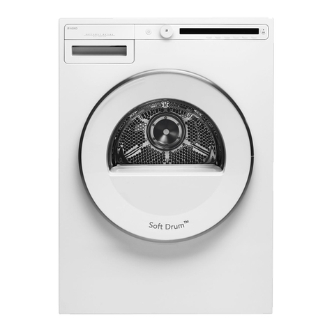
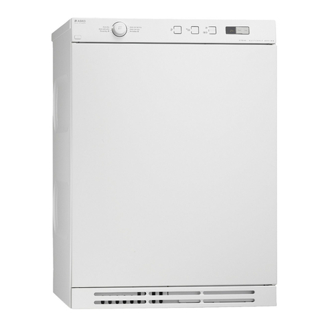
Asko T700 Series User manual

40
50
55
45
65
70
60
1
2
3
4
6
7
8
9
11
12
13
14
16
17
18
19
21
22
23
24
0
5
10
15
20
25
26
27
28
29
31
32
33
34
36
37
38
29
41
42
43
44
46
47
48
49
35
30
51
52
53
54
56
57
58
59
61
62
63
64
66
67
68
69
Asko-App l i ancesAsko - App l i ances
BUILT TO LAST LONGER
ASKO
SERVICE
ACADEMY
Service Manual
for the 700
Series of
Tum le Dryers

INTRODUCTION
You have in your hand the ASKO Service Manual for the new generation of tumble
driers, that are friendly to the environment in both their manufacture and their use.
This new generation of tumble driers has been designed for ease of servicing. By this
we mean that it's a simple job, for example, to replace a damaged side panel.That's
why we've changed the design from a one-piece shell to a split shell.
To secure parts and wiring, we have replaced many of the screws by plastic snap
fasteners, and certain parts have integrated ribbon cabling, all for simplifying service.
We have also integrated service aids, such as hooks to hang parts on, so that you
can use both hands for installation.
Presentation of the different models:
T700 - is a thermostatically-controlled tumble dryer with air extraction
T720 - is a timer-controlled tumble dryer with a condenser
T760 - is a sensor-controlled electronic tumble dryer with air extraction
T780 - is a sensor-controlled electronic tumble dryer with a condenser
The T760 and T780 are equipped with internal lighting. They have a humidity
sensor that can tell when the clothes are dry.
You can choose from a total of eleven different languages on the display, the
number and choice of languages depend on the market.
Servicing the tumble driers has to be easy, and just as it is important for us that the
customer shall be satisfied with our simple, able and durable 700 series, so we also
want to give you, the service engineer, the conditions to permit you to work effi-
ciently and satisfactorily.
We hope that this Service Manual will be a positive tool in your daily work, and
you are welcome, if you have any questions concerning servicing ASKO products, to
contact us at the after-sales department of ASKO Cylinda AB in Vara.

5
SAFETY REGULATIONS
GENERAL
• The electrical and plumbing installations shall
be carried out by a qualified electrician and
plumber respectively.
SERVICE
WARNING
Always switch off the main electrical power supply
when dismantling and assembling the washing
machine.
• Always use an earthed EMC wristband when
working with electrical components, such as
panel printed circuit boards and electronic
control units.
T720: TRANSPORT/WINTER STORAGE
If the tumble drier is to be transported, or stored
for the winter in unheated premises, ensure that
the condensation water tank has no water in it.
T780: TRANSPORT/WINTER STORAGE
If the tumble drier is to be transported, or stored
for the winter in unheated premises, ensure that
the condensation water tank has no water in it.
DISPOSAL
When the tumble drier comes to end of its useful
life and is to be scrapped, it must be immediately
rendered unusable.
Contact your local authority to find out how the
tumble drier should be scrapped and recycled pro-
perly.
The tumble drier is manufactured and labelled
for recycling.
SAFETY REGULATIONS

6
SPECIFICATIONS
PRINCIPAL DIMENSIONS
Height: 850 mm
Width: 595 mm
Depth: 585 mm
Weight:
T700 39 kg
T720 47 kg
T760 39 kg
T780 47 kg
VOLUME/CAPACITY
Drum volume 111 litres
Drying capacity - EU: 5.0 kg
Drying capacity - AU: 5.0 kg
Speed: 52 rpm
ELECTRICAL CONNECTION ALTERNATIVES
Power consumption: See type label
Heating element power: See type label
Drying drum material:
Stainless steel.
Outer casing material:
Powder-painted and hot galvanised steel plate
or stainless steel.
Installation:
Tower, free-standing or built-in.
Drain
T720/780: 2.0 m rubber hose
Air extraction hose
T700/760: 3.0 m PVC
Lamp
T760/780: 10 W, E14 socket
SPECIFICATIONS

7
THE DRYING PROCESS
THE DRYING PROCESS
T700:
Air at room temperature is heated by the heating
element and drawn into the drum, where it ex-
tracts the dampness from the clothes. The ridges
in the drum prevent the clothes from sticking to
each other.
Air passes through the fluff filter in the front door,
through the exhaust system and out.
T760:
Air at room temperature is heated by the heating
element and drawn into the drum, where it ex-
tracts the dampness from the clothes. The ridges
in the drum prevent the clothes from sticking to
each other.
Air passes through the fluff filter in the front door,
through the exhaust system and out.
On the way through the air extraction system the
air passes a humidity sensor. The sensor measures
the amount of humidity in the clothes. If you are
using an automatic program, the sensor indicates
when the clothes are dry.

8
THE DRYING PROCESS
T720/780:
The condensing tumble drier has two circulation
systems: one for drying air and one for cooling
air. The black arrows show the warm drying air,
and the white arrows the cooling air at room tem-
perature.The ridges in the drum prevent the clo-
thes from sticking to each other. On the way th-
rough the air extraction system the air passes a
humidity sensor. The sensor measures the amount
of humidity in the clothes. If you are using an
automatic program, the sensor indicates when the
clothes are dry.
AIR DRIER
Air at room temperature is heated by the heating
element and passes through the drum, where it
blows through the clothes and extracts the damp-
ness from them.
The air is filtered through the fluff filter in the
front door, goes down to the fan and onwards to
the condenser unit.
On its way through the condenser the saturated
air releases its water content.The extracted water
falls into a holder, from which it is either pum-
ped up to a water tank or taken out via a drain
hose to a floor drain or similar.
COOLING AIR
The condenser is cooled by air at room tempera-
ture, drawn in through the rear of the machine.
The air is blown through the condenser and ex-
hausts through a grille in the bottom hatch. If
the machine is built in, the air is drawn through
the gap between the floor and the bottom of the
machine.

9
INSTALLATION
A
B
C
min
600
min
850
120
103
140 135
INSTALLATION
TUMBLE DRIER LOCATION
T720/780:
The tumble drier can be free-standing, built in or
part of a tower. Remember that the tumble drier
produces heat, and should therefore not be pla-
ced in too confined a space. If the tumble drier is
put into a very small room, because of the limi-
ted amount of air, the drying process will take
longer.
NOTE
To improve the air circulation, leave the door le-
ading into the room where the tumble drier is
placed open.
WARNING
The electrical installation must be carried out by
a qualified tradesman.
LOCATION ALTERNATIVES:
A. Free-standing
The tumble drier can be placed on the floor, either
on its own or up against a wall or cupboard.
B. Built-in
The tumble drier can be built in under a work
top with a minimum working height of 850 mm.
The width of the opening must be at least 600
mm.
C. Washing tower
The tumble drier can be placed on top of an ASKO
washing machine. The tumble drier is fastened
securely and prevented from moving by the to-
wer fasteners that come with the machine:
2 off angle pieces.
2 off plastic cups.
A pull-out worktop is available as an accessory
(Part no. 80 619 07-0 - white, 80 619 07-26 -
black), available for purchase from your local
ASKO dealer.

10
INSTALLATION
2
1
3
Install the tower configuration like this:
1. Unscrew and remove the outermost screws
from each side of the rear of the washing
machine.
2. Screw the angle pieces to the rear of the wash-
ing machine.
3. Secure the two plastic cups to the front edge
of the top cover.
WARNING
The plastic cups must be fitted, they secure the
front edge of the tumble drier.
Right side: Break off the left-hand tag from
one of the plastic cups and remove the paper
from the underside. Position the cup so that
the arm that sticks out is flush with the front
edge of the panel and press it firmly into pla-
ce.
Left side: Break off the right-hand tag from
the other plastic cup and remove the paper
from the underside. Position the cup so that
the arm that sticks out is flush with the front
edge of the panel and press it firmly into pla-
ce.
4. Position the tumble drier by fitting the two
angle pieces into the slots at the rear of the
tumble drier while keeping the front edge of
the tumble drier raised by 1 - 2 cm.
5. Lower the tumble drier so that its front feet
enter the plastic cups. Adjust the feet as neces-
sary to straighten the tumble drier vertical.

11
INSTALLATION
max 1000 mm
1
2
3
ADJUSTING THE FEET
Screw the feet in or out until the tumble drier is
standing vertical and steady. Lock the feet by tight-
ening their locking nuts.
CONDENSATION WATER (T720/780)
Alternative 1 (as delivered)
Condensation water is pumped up into the con-
densation water tank, which is pulled out and
emptied manually.
Alternative 2
By connecting the accompanying rubber hose to
the blue nipple and leading it down to a floor
drain, the condensation water is pumped directly
out to the drain.
Alternative 3
By connecting the accompanying rubber hose to
the blue nipple and leading it to a sink or similar,
condensation water is pumped directly out to the
drain.

12
INSTALLATION
ABC
A
AIR EXTRACTION (T700/760)
The exhaust air from the tumble drier should be
taken to an exhaust duct or a wall outlet with the
aid of the accompanying air extraction hose.
Connection to the tumble drier
The tumble drier has three possible air extraction
points: the rear, right or left side. On delivery one
of the holes is open, and the other two are closed
by covers.
The tumble drier is delivered with a connec-
ting flange (A), a plastic ring (B) and an air ex-
traction hose (C).
Install the air extraction system as follows:
1. Push the air extraction hose on to the connec-
ting flange and secure it with the plastic ring.
2. If necessary, remove the plastic cover from the
hole where you want to connect the hose.
3. Insert the connecting flange and air extraction
hose into the chosen hole.
4. Close the other two holes with the plastic
covers.
Connection to exhaust duct
The air extraction hose must be routed the short-
est possible way and as straight as possible from
the tumble drier to the exhaust duct. Cut the air
extraction hose if it is too long. If necessary the
air extraction hose can be extended by up to a
maximum of 8 metres (inner diameter 102 mm).
If a longer hose is needed, the inner diameter must
be increased in order to retain the fan capacity of
the tumble drier.
Any bends must be made as gentle as possible.
If 90º bends are necessary, there should be no more
than four. Each bend reduces the fan capacity of
the tumble drier.
If the air extraction hose leads to a wall outlet,
the entry of cold air can be cut down by installing
a ventilation grille (part no. 92 059 00).The ven-
tilation grille can be installed either outside or
inside.
If there is only one exhaust duct leading from
the room a draught break (A) must be installed
(part no. 92 059 01).

13
INSTALLATION
ELECTRICAL INSTALLATION
The electrical installation must be carried out by
a qualified tradesman.
The installation is made using fixed wiring and
a multi-pole breaker.
Connections on delivery
The machine is supplied for 3-phase, 400 V, hea-
ting power 2500/2620 W (see type label) and
fused at 10 A.
If an earth fault breaker is installed, it should
be of type A.
Rewiring to single-phase
The machine can be rewired to single-phase, 10
or 16A. For rewiring to single-phase a 3-wire ca-
ble and wall plug are required. Rewiring shall be
carried out in accordance with the rewiring dia-
gram (supplied with the machine, in the front
beam).
• 1-phase, 230 V, 50 Hz, heating power 1900
W, fused at 10 A (T700/720/780).
• 1-phase, 230 V, 50 Hz, heating power 2500/
2620W, fused at 16A (T760).
IMPORTANT
Electrical connections/rewiring must be carried
out by a qualified tradesman.
T780 (Condenser tumble drier with display):
For the machine to show the correct remaining
drying time, after rewiring select the Low heating
power (or High if you rewire to 3-phase).
Do this:
Switch off the mains power button, , and
press it again to restart the machine.
Press the
Enter
button 5 times, then press the
P2
button 5 times. These 10 button presses must be
done within 15 seconds.
Within 3 seconds of the last button press select
Low with the buttons.
Joint connection of the tumble drier and an
ASKO washing machine
NOTE
Joint electrical connection as described below
must be carried out by a qualified tradesman.
To ensure even loading of the phases when in-
stalling the tumble drier jointly with a single-phase
ASKO washing machine, the phases should be
connected like this:
Tumble drier:
Terminal labelled L1 to phase 1.
Terminal labelled L2 to phase 1.
Terminal labelled L3 to phase 2.
Washing machine:
Terminal labelled L to phase 3.

14
DOOR HANGING
8
9
7
7
2
2
3
5
DOORHANGING
The tumble drier's front door can be adjusted to
hang on either the left or the right.
Tumble driers are normally delivered with the
door hanging on the left.
Left hanging to right hanging:
1. Keep the front door closed, it will be held in
position by the door magnet.
2. Remove the bottom cover and unscrew the
3 screws that secure the hinge fixing.
3. Tilt the hinge fixing so that it comes free from
the hinge socket in the front door.
4. Lift down the front door.
5. Change the hinge pin over.
6. Then change over the hinge pin for the up-
per hinge.
7. Then change over the plastic plugs and the
hinge sockets located on the upper and lo-
wer edges of the front door respectively. Use
a flat-bladed screwdriver.
8. Half unscrew the two screws on the sides of
the front door.
9. Then take out the door magnet and cover
washer.
Right side: Push the magnet/washer upwards
and pull them out.
Left side: Push the magnet/washer down-
wards and pull them out.
10. Fit the door magnet and cover washer.
11. Screw in the two screws on the sides of the
front door.
12. T720/780: Open the condenser housing co-
ver.

15
DOOR HANGING
12 13
a
bc
d
15
13. Remove the screw that is securing the front
panel at the bottom edge of the side where
the hinge will be installed.
14. Keep the front door in place with the door
magnet.
15. Install the hinge fixing in the order a,b,c,d.
16. Refit the screw that secures the front panel at
the bottom edge.
17. T720/780: Close the condenser housing co-
ver.
18. Refit the bottom cover.

16
DOOR HANGING
34
5
8
11
12
10
10
Right hanging to left hanging:
1. Keep the front door closed, it will be held in
position by the door magnet.
2. Remove the bottom cover.
3. T720/780: Open the condenser housing co-
ver.
4. Remove the 3 screws that secure the hinge
fixing and the lower screw that secures the
front panel.
5. Tilt the hinge fixing so that it comes free from
the hinge socket in the front door.
6. Tighten the lower screw securing the front
panel.
7. Lift down the front door.
8. Change the hinge pin over.
9. Then change over the hinge pin for the up-
per hinge.
10. Then change over the plastic plugs and the
hinge sockets located on the upper and lo-
wer edges of the front door respectively. Use
a flat-bladed screwdriver.
11. Half unscrew the two screws on the sides of
the front door.
12. Then take out the door magnet and cover
washer.
Right side: Push the magnet/washer upwards
and pull them out.
Left side: Push the magnet/washer down-
wards and pull them out.
13. Fit the door magnet and cover washer.
14. Screw in the two screws on the sides of the
front door.
15. Keep the front door in place with the door
magnet.

17
DOOR HANGING
a
b
c
16. Install the hinge fixing in the order a,b,c.
17. T720/780: Close the condenser housing co-
ver.
18. Refit the bottom cover.

18
FAULT TRACING
THE MACHINE WILL NOT START
Check
• that the outer lid is properly closed.
• that the mains power button is pressed in.
• that you have set the program or the desired
timer program correctly.
• that the condensation water tank is empty.
(T720/780)
• that if a power plug is used it is connected.
• that the fuses for the house electricity supply
are not blown. Change two of the fuses over.
It is not always visible from the outside when
a fuse is blown.
• that the overheating protection has not trip-
ped, see below.
OVERHEATING PROTECTION
The overheating protection switches off the tum-
ble drier if the temperature is too high, e.g. be-
cause fluff is blocking the fluff filter. Clean the
filter, empty the condensation water tank and cle-
an the condenser. Then reset the overheating pro-
tection by pressing on the rubber membrane at
the rear of the machine.
TUMBLE DRYING IS TAKING TOO LONG
(T700/760):
Check that the fluff filter is not blocked.
(T720/780):
Empty the condensation water tank and check
that the fluff filter or condenser are not blocked.
Too long drying time can also be due to the fact
that the tumble drier is located in too small a spa-
ce and that the air in the room (cooling air) is
becoming too warm. Make sure that the Se till
that tumble drier has access to more cool air, e.g.
by opening a door or window.
NO INTERNAL LIGHTING
Check
• that the mains power button is pressed in.
• that if a power plug is used it is connected.
• that the fuses for the house electricity supply
are not blown. Change two of the fuses over. It is
not always visible from the outside when a fuse is
blown.
• that the lamp has not blown. Switch off the
mains power. The lamp is located inside the up-
per edge of the drying drum, just inside the ope-
ning. Unscrew the plastic housing that protects
the lamp, unscrew the lamp and change it if it is
faulty.
ERROR MESSAGES
The display text field shows a message if a fault
occurs during the time the program is running.
The error messages that may be shown are:
Maximum program time: When the machine
has been running for its maximum time (3 hours)
it will stop. Check and if necessary change the
mains power fuses in the house fuse board. To
remove the error message, switch off the machi-
ne or open its door. If this does not help, ring for
service.
Thermistor error: Ring for service.
Sensor error: Fault in the humidity sensor. This
error message may also appear if you run the
machine with laundry that is already dry, or run
it empty. Open the door and the message should
disappear. If it does not, ring for service.
Overfull: (T780) Means that the condensation
water tank is full. Empty it and restart. If the same
error message appears again, it can mean that the
bottom water container is full, because the pump
or hoses are blocked or faulty. If the condensate
water is pumped straight out via the drain hose -
check that the hose is not kinked or blocked. If
this does not help, ring for service.
FAULT TRACING

19
FAULT TRACING
INCORRECT LANGUAGE ON THE DISPLAY
If for some reason the language on the display has
changed, you can go back to the original langua-
ge.
Earlier models had two versions of the machine
(Alternatives 1 and 2) but now all eleven langua-
ges are present in all machines.
Alternative 1: The languages you can choose
from are Danish, Finnish, French, Dutch, Nor-
wegian and Swedish.
Alternative 2: The languages you can choose
from are English, French, Italian, Portuguese,
Spanish and German.
To change the language, do this:
Switch off the mains power button, , and
press it again to restart the machine.
Press the button five times, then press the
button five times. These 10 button presses
must be done within 15 seconds.
Within 3 seconds of last pressing the but-
ton, use the buttons to step through to
the language you want.

20
PROBLEMS
COMMON QUESTIONS AND PROBLEMS
The washing will not dry?
The machine only runs for 20 minutes?
1. Mains power fuse has blown.
2. Overheating, fluff blocking the filter, conden-
ser unit or fan housing.
3. Overfilling: The display shows "Fault indica-
tion, filling"
4. The machine does not reach the measured
value of 1,8 mV within 15 minutes.
This can be due to:
- Incorrect connection to single phase = too
low heating element power (720 or 600 W)
- Incorrect connection of element to control
unit
- Incorrect connection in element terminal
block
- Humidity sensor not located in fan hous
ing
- Faulty humidity sensor
- Heating element open circuit
5. Drive belt running incorrectly on motor shaft
= too high drum speed > 56 rpm
Overheating protection tripped even though
fluff filter and condenser unit have been
cleaned.
1. Fault in control unit
2. Fluff in internal fan wheel - clean also air ducts
and behind the element.
3. Motor overheating protection tripped.
Overfilling fault indication, even though tank
is empty.
Condenser water pump is blocked or burned out.
If the pump is burned out an associated fault will
be burned wiring in the control unit. Always check
first if the condenser water pump has burned out
before installing a new control unit.
See service bulletin Group 22 Number 21.
The machine shows the Maximum program
time fault indication.
The indication means that the machine has been
running for the maximum time (= 3 hours) that
the control unit is allowed.
This can have several independent reasons, or a
combination of these.
1. Mains power fuse has blown
2. Fluff in the filter, condenser unit or fan hou
sing.
3. Incorrect connection to single phase, 10A
4. External air is restricted or blocked, resulting
in poor condensation
5. High ambient temperature + low heating ele
ment power + low drying temperature resul
ting in poor condensation
6. Low ambient temperature + low heating ele
ment power + low drying temperature so that
it is difficult to get the dampness out of the
clothes .
7. The washing has been spun dry at low speed,
i.e. less than 800 rpm
8. The washing has been taken out before the
program was completed. The machine was
then loaded with a new batch of washing. In
that case the control unit did not have time
to reset itself and the time was added to the
next drying cycle.
9. Damaged humidity sensor, its wiring or con
nections.
PROBLEMS

21
COMPONENTS AND MEASUREMENT VALUES
MOTOR (2/118/JU)
50 Hz
Part no.: 80 618 24
Main winding: 23,8 Ω
Auxiliary-
winding: 28,1 Ω
Voltage: 220/240 V
Current: 1,1 A, 270 W, 2850 rpm
The 2-pole motor is connected directly to the fan
for internal air, and via a gear to drive the drum.
On machines with condensers (T720/780) it also
drives the fan for external air.
CAPACITOR
Part no.: 80 542 68
The capacitor is located on the motor and has a
value of 8µF.
CONDENSATE WATER PUMP
HANNING
T720/780 25W
Part no.: 80 638 09
Resistance: 111 Ω
PLASET
T720/780 25W
Part no.: 80 565 19
Resistance: 101 Ω
The condensate water pump pumps the water
from the condenser housing to the water tank.
RADIO INTERFERENCE FILTER
Part no.: 80 585 58
Leakage current: 230 V/ 50 Hz 0.315 mA ??
The filter eliminates radio interference generated
by the machine.
INDICATION LAMP
Part no.: 80 070 73
Current: 1.68 mA, 230 V, 50 Hz
The lamp indicates that the main power switch is
set to on.
THERMISTOR
Part no.: 80 619 00
Resistance: 40-60 kΩ at 20°-30°C
The thermistor controls temperature regulation.
If the thermistor becomes short-circuited or dis-
connected from the control unit, the program
stops.
CONTACTOR
Part no.: 80 091 48
Resistance: 2 kΩ
The contactor opens in case of overheating, when
the door is opened and at the end of the pro-
gram.
THERMOSTAT
T700
Part no.: 80 619 46 (44°C)
Part no.: 80 014 45 (53°C)
Part no.: 80 088 07 (115°C auto.)
The thermostats are located in the fan housing,
controlling the automatic programs for 44°C and
53°C, also the time program up to 60 min. The
115°C thermostat automatically disconnects one
of the heating loops if the temperature rises too
high.
T760
Part no.: 80 144 44 (47°C)
Part no.: 80 560 29 (70°C)
The thermostats are located in the fan housing,
controlling the automatic programs for 47°C and
70°C, also the time program up to 60 min.
KOMPONENTER OCH MÄTVÄRDEN

22
COMPONENTS AND MEASUREMENT VALUES
T700/720/760/780
(OVERHEATING PROTECTION)
Part no.: 80 084 87 (150°C manual)
The 150°C thermostat stops the program if the
temperature rises too high and has to be manual-
ly reset. This thermostat is also called the over-
heating protection.
HUMIDITY SENSOR
Part no.: 80 618 55
The humidity sensor is used to control the dry-
ing process. During operation the sensor output
signal is between 1 and 16 mV DC. Any other
value causes the program to stop.
DOOR SWITCH
Part no.: 50 531 07
The front-loading door operates a door switch,
and when this is open the program stops. If the
door has been opened and closed again during the
program, the machine must be restarted with the
start button.
INTERNAL LIGHTING T760/780
Part no.: 80 618 62
The internal lighting is controlled by the door
switch.
BUZZER T700/720
Part no.: 80 618 83
The buzzer sounds to indicate that the program
has finished.
OVERFILLING PROTECTION T720/780
Part no.: 80 526 43
If both of the tumble drier containers are overfil-
led, the program is halted by a switch located in
the lower container. The display indicates overfil-
ling.
ELECTRICAL CONNECTIONS
The machine is delivered set for 3 phase, 230V,
10A with heating power 2620W (T760) or
2500W (T700/720/780). The machine can be
rewired for single phase, 16A with heating power
2620W (T760) or 2500W (T700/720/780) or
single phase, 10A with heating power 1900W.
The connection cable is 2.0 metres of RKK 5x1.5
mm2.
PROGRAM CONTROL (T760/780)
Program unit
The control unit contains microprocessors to con-
trol the program, motor, heating element etc.
LIQUID CRYSTAL DISPLAY UNIT (Panel board)
The LC display unit include press buttons and
indications.
PROGRAMMER (T700/720)
The programmer has mechanically marked set-
ting points, and a motor with 4-minute steps.
Other manuals for T700 Series
6
This manual suits for next models
3
Table of contents
Other Asko Dryer manuals