ASO ELMON 41-322 User manual

ELMON relay 41-322 / 41-822
Safety Relay
OperangManual (seelastpageforvalidity)
ELMONrelay 41-822 / 41-322 Safety Relay
English
Page03-14
U.S.Edion2017
© ASO GmbH

Übergabedokumenta� on / Documenta� on / Documenta� on de
data� on / Documentazione di consegna / Documenta� e
Funk� onsprüfung / Func� onal test / Contrôle de fonc� on / Controllo funzionale / Func� econtrole

ELMON relay 41-322 / 41-822
Safety Relay
3
1. TableofContents
1. TableofContents . . . . . . . . . . . . . . . . . . . . . . . . . . . 3
2. Generalsafetyregulaonsandproteconmeasures . . . . . . . 4
3. Generalandfuncondescripon . . . . . . . . . . . . . . . . . . 5
4. Intendeduse . . . . . . . . . . . . . . . . . . . . . . . . . . . . . . 6
5. Applicaonexample. . . . . . . . . . . . . . . . . . . . . . . . . . 6
6. Deviceoverview . . . . . . . . . . . . . . . . . . . . . . . . . . . . 7
6.1 Versions . . . . . . . . . . . . . . . . . . . . . . . . . . . . . . . . . . . . . . 7
6.2 Signalindicators . . . . . . . . . . . . . . . . . . . . . . . . . . . . . . . . . . 7
6.3 Conneconterminals . . . . . . . . . . . . . . . . . . . . . . . . . . . . . . . 7
6.4 DIPswitchforconguringtheoperangmode . . . . . . . . . . . . . . . . . 8
7. Operangmodes . . . . . . . . . . . . . . . . . . . . . . . . . . . 8
7.1 Safetyoutput . . . . . . . . . . . . . . . . . . . . . . . . . . . . . . . . . . . . 8
7.2 Automacreset . . . . . . . . . . . . . . . . . . . . . . . . . . . . . . . . . . 8
7.3 Faultself-retaining–manualreset . . . . . . . . . . . . . . . . . . . . . . . . 8
7.4 Signalingoutputwithoutanydelay(RLU) . . . . . . . . . . . . . . . . . . . . 8
7.5 Signalingoutputdelayed(RL) . . . . . . . . . . . . . . . . . . . . . . . . . . . 8
8. Mechanicalmounng . . . . . . . . . . . . . . . . . . . . . . . . . 9
9. Electricalconnecon . . . . . . . . . . . . . . . . . . . . . . . . . 9
9.1 Supplyvoltage . . . . . . . . . . . . . . . . . . . . . . . . . . . . . . . . . . . 9
9.2 Conneconofsensor . . . . . . . . . . . . . . . . . . . . . . . . . . . . . . . 9
9.3 Conneconofmulplesensorspersensorcircuit. . . . . . . . . . . . . . . . 9
9.4 Conneconofcontrolcircuits . . . . . . . . . . . . . . . . . . . . . . . . . . 10
9.5 ConneconReset. . . . . . . . . . . . . . . . . . . . . . . . . . . . . . . . . 10
9.6 Conneconofsignalingcontact. . . . . . . . . . . . . . . . . . . . . . . . . 10
10.Commissioningandfuncontesng . . . . . . . . . . . . . . . . .11
11. Faultdiagnosis . . . . . . . . . . . . . . . . . . . . . . . . . . . . .11
12.Decommissioninganddisposal. . . . . . . . . . . . . . . . . . . .11
13. Technicaldata . . . . . . . . . . . . . . . . . . . . . . . . . . . . .12
14. WarningsandDisclaimers. . . . . . . . . . . . . . . . . . . . . . .13
15. ECDeclaraonofConformity. . . . . . . . . . . . . . . . . . . . .14
4
Safety Relay
2.Generalsafetyregulaonsandproteconmeasures
• Themanufactureranduserofthesystem/machineon which the protectionsystemis used are
responsibleforcoordinangandadheringtoallapplicablesafetyrulesandregulaonsundertheirown
responsibility.
• The proteconsystemguaranteesfunconal safetyin combinaonwiththesuperordinatecontrol
system,butnotthesafetyof the enresystem/machine.Thus, asafetyreviewoftheenresystem/
machineinaccordancewithmachinedirecve2006/42/ECorrelevant productstandards is necessary
priortouseofthedevice.
• Theoperanginstruconsmustbepermanentlyavailableat the operanglocaonof the protecon
device.They mustbethoroughlyreadandappliedby everypersonwho is taskedwiththeoperaon,
maintenanceorrepairoftheprotecondevice.
• Theinstallaonand start-up oftheprotecondevicemayonlybe conductedbyspecializedpersonnel
whoare familiarwith these operanginstrucons and the applicableregulaonson job safetyand
accidentprevenon.Theinstruconsintheseoperanginstruconsmustbefollowedandadheredto
uncondionally.
• Electricalworkmustonlybecarriedoutbyskilledelectricians.Safetyregulaonsforelectricalengineering
andfromtheprofessionalassociaonmustbefollowed.
• Incaseworkhastobecarriedoutontheswitchingdevice,itmustbeswitchedtoavoltage-freeposion
andcheckedforfreedomfromanyvoltageandsecuredagainstbeingswitchedbackonagain.
• Ifthepotenal-freeconneconsofthesafetyswitchingcontactsaresuppliedwithahazardousvoltage
froman externalsource, it mustbeensuredthat these arealsoswitchedo when working on the
switchingdevice.
• Theswitching devicedoesnotcontainanycomponentsthat the user mustservice. Anywarrantyor
liabilityonthepartofthemanufacturerisforfeitedintheeventofanyunauthorizedmodicaonsor
repairstotheswitchingdevice.
• Auxiliary outputs mustnotexecute anysafety-orientatedfuncons.Theyare not fail-safeandarenot
checkedeitherbytesng.
Thesystem mustbecheckedforcorrectfuncon in suitableintervalsbyqualied personsfor
thestandard-conformdesignofthesafetysystem.Thecheckmustbedocumentedinawaythat
allowsittobetracedatanyme.
Inthecaseofnon-complianceordeliberateabuse,themanufacturer’sliabilitywillcease.
!
ELMON relay 41-322 / 41-822
SafetyRelay
5
3.Generalandfuncondescripon
The ELMON relay 41-822 (41-322) switching device is used to evaluate sensors such as safety
contactmats,safetycontactedgesandsafetybumpersforsecuringcrushandshearlocaons.
AnASOsensorcanbeconnectedtotheswitchingdevice.Thesteady-statecurrentmonitoringofthesensor
ismadepossiblebyanintegratedterminangresistorinthesensor.
Furthermore,thedevicecanalsoevaluateasensorinfour-wiretechnology.
Ifthe desiredsteady-statecurrentows, the safetyrelaysare drivenand the switchingcontactsclosed. If
thesensorisoperatedorthesensorcircuitisinterrupted,therelayswitchingcontactsopen.
A signal output with potenal-free switching contacts is available. An operaon of the sensor causes a
reaconofthesignaloutputinaccordancewith the DIP switchconguraon.Thesignaloutputmustnot
executeanysafety-orientatedfuncons.Itisnotfail-safeandnotcheckedbytesngeither.
The switching device has been designed and type-approved in accordance with EN ISO 13849-1 “Safety-
relatedparts of controlsystems”forcategory3PerformanceLevele.For compliancewithcategory3, the
safetyoutputissetupredundantlywithtwoindependentswitchingelements.
Inaddionthe device has been type-approvedaccordingto EN 62061 “Funconalsafetyofsafety-related
electrical, electronic and programmable electronic control systems“ and can meet a safety funcon up to
SIL 3.
ThemonitoringstateofthesensorandtheappliedoperangvoltageareindicatedbyLED.
Ifthereisafaultalarm,allsafetyoutputsareinacve.
Installaonandelectricalworkmustbeperformedbyauthorizedelectricians.
The unit can be used in a household environment as well as an industrial environment up to
analtudeof2000mabovemeansealevel.Theunitmustnotbeoperatedinareaswithmajor
temperaturechanges.
!
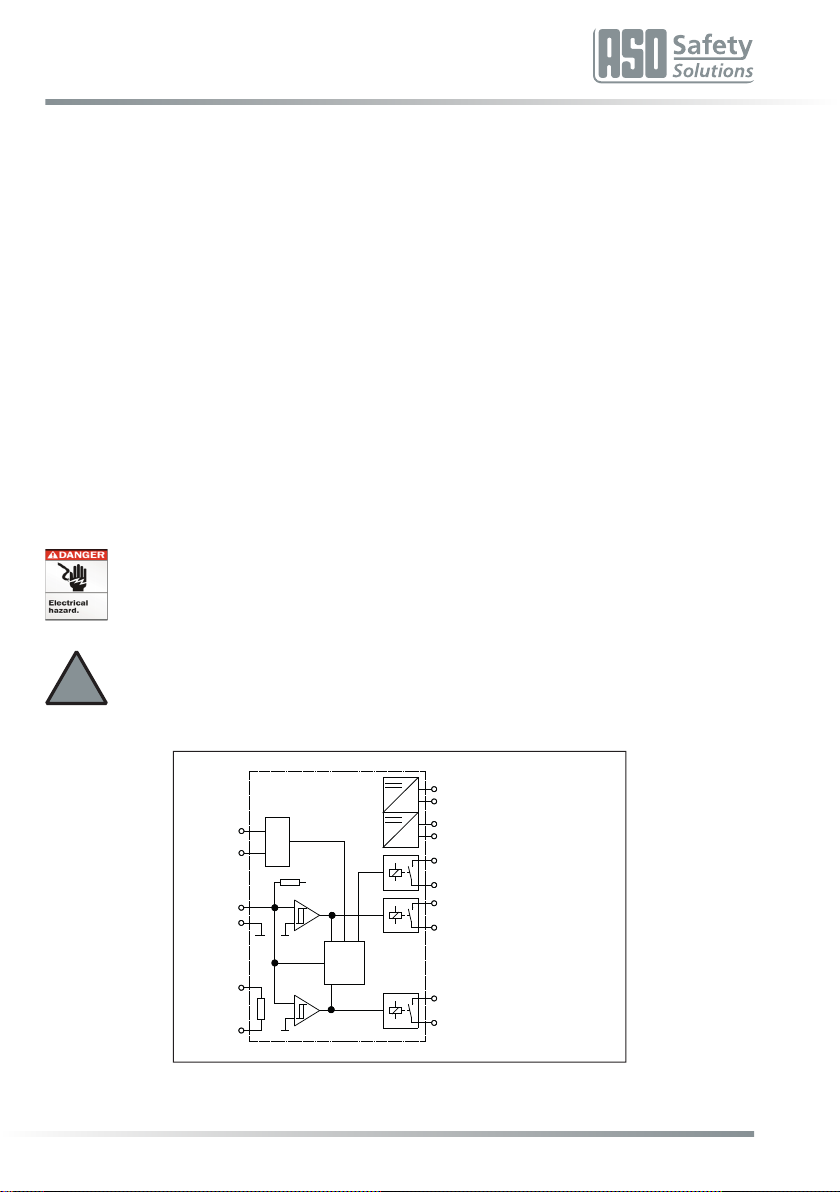
Func onal circuit diagram
Logic
Mode
Reset
R
+U2 AUX1
OUT
REL1
OUT
Reset
Manual Z1
Z2
X1
X2
X3
X4
SIG
A1
A2
B1
B2
31
32
13
14
23
24
24VAC/DC
REL2
OUT
ELMONrelay41-322:230VAC
(ELMONrelay41-822:120VAC)

6
Safety Relay
4.Intendeduse
Theswitchingdevicecanonlyfulllitssafety-relevanttask,ifitisusedasintendedwithinspecicaons.
Theintendeduseoftheswitchingdeviceistheuseasaproteconsysteminconneconwithsafetycontact
mats,safetybumpersandsafetycontactedgeswith8.2kΩresistanceforsteady-statecurrentmonitoring.
Itisnotallowedtousethesafetyrelayinheightsover2000mabovesealevelorpotenallyexplosive
atmospheres.
Adierentuseoranyusegoingbeyondtheintendeduseisnotwithinspecicaons.Themanufacturer
doesnotacceptanyliabilityforanydamagearisingfromusenotwithinspecicaons.
Anyuseforspecialapplicaonsrequirespriorreleasebythemanufacturer.
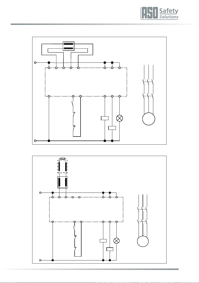
5.Applicaonexample
Safety-orientatedmonitoringofasafetycontactedgewithstartreleaseviareleasepushbuonandseparate
connuaonofthecontrolcircuits(category3compliantapplicaonaccordingtoENISO13849-1).
InordertocheckthefunconalityoftheloadbreakingK1andK2relaysthebreakcontactsofthesecontactors
areintegratedintothestartcircuit(Z1Z2).
Thesignalingrelayoutputisusedtovisualizetheswitchingstateofthesafetycontactstrip.
Circuitdiagraminvoltage-freestate.Sensornotoperated.
1Sensor(edge,matorbumper)
2Releasekey
+24V
M
13
14
K2
23
24
33
34
L1 L2 L3
31
8,2 ΚΩ
14
K1
24 34
13 23 33
2313X2X1B1 X4X3
S1
322414B2 Z2Z1
41
41
42
42
K2
K1 X1
Reset
0V
5.12-WireSingleApplicaonExample
ELMON relay 41-322 / 41-822
Safety Relay
7
5.24-WireSingleApplicaonExample
5.32-WireMulpleApplicaonExample
+24V
M
13
14
K2
23
24
33
34
L1 L2 L3
31
8,2 ΚΩ
14
K1
24 34
13 23 33
2313X2X1B1 X4X3
S1
322414B2 Z2Z1
41
41
42
42
K2
K1 X1
Reset
0V
S1
S“n“
8k2Ω
+24V
M
13
14
K2
23
24
33
34
L1 L2 L3
31
8,2 ΚΩ
14
K1
24 34
13 23 33
2313X2X1B1 X4X3
S1
322414B2 Z2Z1
41
41
42
42
K2
K1 X1
Reset
0V

8
Safety Relay
5.44-WireMulpleApplicaonExample
+24V
M
13
14
K2
23
24
33
34
L1 L2 L3
31
8,2 ΚΩ
14
K1
24 34
13 23 33
2313X2X1B1 X4X3
S1
322414B2 Z2Z1
41
41
42
42
K2
K1 X1
Reset
0V
S1 S“n“

ELMON relay 41-322 / 41-822
SafetyRelay
9
6.Deviceoverview
6.1Versions
Version Supplyvoltage
ELMONrelay41-822 120V50/60Hzand24VAC/DC
ELMONrelay41-322 230V50/60Hzand24VAC/DC
6.2Signalindicators
LED Power(green)
Operangstate(on)
Faultalarm(pulse)
LED CH1(red)
Sensoroperated(on)
Sensorpowercircuitinterrupted(fastashing)
Faultself-retaining(slowashing)
LED AUX 1(yellow)
Signaloutputswitched
Ifthereisnofaultalarm,thentheoperangstateisshownviathePowerLED(on).Whenafaultalarmisissued,
thenumberofpulsesoutputindicatesthefault:
Pulse Faultalarm
1Voltagesupplyoutsidethevalidvaluerange
2Faultwhentesngsignalinput
3Outputcontrolrelayfaulty
4Datatransmissionbetweenmicro-controllersfaulty
6.3Conneconterminals
A1 A2 ELMONrelay41-822:Supplyvoltage120V50/60Hz
ELMONrelay41-322:Supplyvoltage230V50/60Hz
B1 B2 Supplyvoltage24VAC/DC
X1 X2 Conneconsensor
X3 X4 Internalterminangresistor
13 14 Switchingcontactsafetyrelay1
23 24 Switchingcontactsafetyrelay2
31 32 Switchingcontactsignalrelay
Z1 Z2 Conneconmanualreset/re-start(keyNO;oponal)
Installaonandelectricalworkmustbeperformedbyauthorizedelectricians.
Wronginstallaoncancausehazardouscondions.
ELMONrelay
41-322/41-822

10
Safety Relay
6.4DIPswitchforconguringtheoperangmode
S1
„ON“:Automacreset
„OFF“:Faultself-retaining–manualreset(factoryseng)
S2
„ON“:AUX1Modesignaloutput:RLU
„OFF“:AUX1Modesignaloutput:RL(factoryseng)
7.Operangmodes
7.1Safetyoutput
Separateorseries-connectedoutputofthecontrolcircuits(redundantconnuaonoftheswitchingcontacts).
Inordertousethetwosafetyrelaysseparately,thebridgebetween14and23mustberemoved.
7.2Automacreset
(S1=„ON“)
Aerremovingafaultinasensorcircuitoraeravoltagefailure,theswitchingunitwillautomacallyrelease
outputagain.
Aenon:Automacrestartofmashine!Ifthissengisused,ithastobeensuredthatnoone
isabletobeinthedangerouszonetoavoidhazardoussituaons.Theintegratororoperatoris
responsibleforthecorrectsengsofthecontroller.Innocasethemanufacturerisliablefor
incorrectsengsormissuse.
7.3Faultself-retaining–manualreset
(S1=„OFF“)
Followingremovalafaultofinasensorcircuit,oraeravoltagefailure,theswitchingunitwillonlyrelease
theoutput(s)again,iftheZ1andZ2contacts,500msaertheeliminaonofthedisrupon,areclosedby
meansofapushbuon.Thiscompletelypreventsanyautomacre-start.ApermanentbridgingoftheZ1and
Z2contactsdoesnotcauseanautomacreset.
7.4Signalingoutputwithoutanydelay(RLU)
(S2=„ON“)
Inthismodeof operationthecorresponding signaling
outputisacvatedwithoutdelay,ifanyfaultissignaledon
thecorrespondingchannel. The output is alwaysinacve
inthede-energizedstateoftheswitchingdevice.
7.5Signalingoutputdelayed(RL)
(S2=„OFF“)
Inthisoperang mode the correspondingsignalingoutput
isacvatedwithadelayof 0.5 secondsandthenremains
acveforamaximumof3seconds,ifafaultissignaled.
!
Output
Aux.Relay
Output
Aux.Relay
3s
0,5s
Safetyoutput(symbolic)
Signalingoutput(symbolic)
Safetyoutput(symbolic)
Signalingoutput(symbolic)

ELMON relay 41-322 / 41-822
SafetyRelay
11
8.Mechanicalmounng
Theswitchingunitmustbemountedcorrectly:
•Inadust-protectedandmoisture-protectedswitchcabinetorcasing.
•Foruseinanenvironmentwithlevel2contaminaon.
•WithaprotecontypeofatleastIP54.
•Ona35mmDINsupportrailaccordingtoEN50022.
Theswitchingunitcanbeinstalledinanyposion.
Theunitmustnotbeoperatedinareaswithmajortemperaturechanges.
9.Electricalconnecon
Installaonandelectricalworkmustbeperformedbyauthorizedelectricians.
Theswitchingunitcanbedestroyedbyconnecontotheincorrectterminals.
Linesthatareroutedintheopenairoroutsidetheswitchcabinetmustbeprotectedaccordingly.
Thelimitvaluesstatedinthe“TechnicalData”forthesupplyvoltageandtheswitchingcapability
oftherelaymustbeobserved.
9.1Supplyvoltage
Thesupplyvoltagecanoponallybeeectedbymeansofamainsvoltageof120VAC50/60Hz
(ELMONrelay41-322:230VAC50/60Hz)oralowvoltageof24VAC/DC.Forasupplywith24V
AC/DCthevoltagemustcorrespondtotherequirementsforprotecvelowvoltages(SELV).The
supplylinetotheswitchingdevicemustbeprotectedbymeansofa5x20glasstubefuse200mA
mediummelag.
Never apply both voltages simultaneously!
The120V(230V)supplyvoltagemustbeappliedtotheA1andA2terminals.Foroperaonwith24V,the
supplyvoltagemustbeappliedtotheB1andB2terminals.
Foraxedinstallaonaseparangdevicemustbeavailable(forexample,amainswitchforthesystem).A
mainsplugissufficientasaseparangdevice,ifitisfreelyaccessible.
9.2Conneconofsensor
Thesensorwithaterminangresistorof8.2kΩmustbeconnectedtotheX1andX2terminals.
ThesensorwithoutaterminangresistorisconnectedtotheX1andX2terminalsbymeansofoneleadand
withtheotherleadtotheX3andX4terminals.
9.3Conneconofseveralsensorspersensorcircuit
ASO-Sensorsmustnotbeconnectedinparallel.
Oneorseveralsensorscanbeconnectedtothesignaltransmierinput.Forthispurpose,theindividual
sensorsareconnectedinseriesinaccordancewithFigure1.
!
!
!
!
Toavoidtheriskofcrushing,Safetyglovesmustbeworn!
Installaonandelectricalworkmustbeperformedbyauthorized
electricians.

12
Safety Relay
SafetycontactedgeSENTIRedge:
Amaximumof5SENTIRedgedevicescanbeconnectedinseries.ThemaximumtotallengthoftheSENTIR
edgemustnotexceed100m.
ThelengthofaSENTIRedgecanbeupto25m.
Thetotallinelengthoftheseries-connectedSENTIRedgemustnotexceed25m.
SafetycontactbumperSENTIRbumper:
Amaximumof5SENTIRbumperdevicescanbeconnectedinseries.ThemaximumtotallengthoftheSENTIR
bumpersmustnotexceed15m.
ThelengthofaSENTIRbumpermaybeupto3m.
Thetotallinelengthoftheseries-connectedSENTIRbumpersmustnotexceed25m.
SafetycontactmatSENTIRmat:
Amaximumof10SENTIRmatscanbeconnectedinseries.Themaximumtotalsurfaceareamustnotexceed
10m2.
ThesizeofaSENTIRmatcanbeupto1350x2350mm.
Thetotallinelengthoftheseries-connectedSENTIRmatmustnotexceed25m.
Beforeconnecngtheseries-connectedsensors,itisrecommendedtomeasuretheresistancevalueofthe
wiring.Inthecaseofnon-operatedsensorstheresistancemustbe8.2kΩ±500Ω.Ifthesensorisoperated,
theresistancemustnotexceed500Ω.
9.4Conneconofcontrolcircuits
Connectthecontrolcircuittobemonitoredtothe13and24terminals.Iftheswitchingcontactsareredundantly
connued,thefactory-insertedbridgebetweenthe14and23terminalsmustberemoved.
Intheeventofanyredundantuseoftheswitchingcontactsonlyvoltageswiththesamepotenal
maybeconnected.Theuseofdierentvoltagepotenalsdoesnotcorrespondtoanyintended
usewithinspecicaons.
Dependingonthenominalcurrent,thecontrolcircuitsaretobeprotectedbyacorresponding
fuse,orthenominalcurrentonthecontrolcircuitsmustbelimitedtothemaximumvalueby
meansofothermeasures.
9.5ConneconReset
Forthe operangmode “manual reset”thenecessaryresetswitchmustbe connectedtothe Z1 and Z2
terminals.
9.6Conneconofsignalingcontact
The31and32signalingcontactonlyservesasanauxiliarycontact(signaling,displayetc.)andmustnotbe
integratedintothesafetycircuit.
Thesignalingcontactmayonlyswitchextralow voltages(24V).Theswitchingof low voltages
120V(230V)isnotpermissible.
Installaonandelectricalworkmustbeperformedbyauthorizedelectricians.
Wronginstallaoncancausehazardouscondions.
Themanufacturersliabilitywilleraseinanycaseofnon-compliantordeliberateabuse.
Fig. 1: Interconnecng several sensors, here using the example of the safety contact edge
Sensor1 Sensor2 Sensor„n“
O
C
2
222
!
!
ELMON relay 41-322 / 41-822
Safety Relay
13
10.Commissioningandfuncontesng
Followingacorrespondingconneconofallelectricalconneconsandswitchingonthesupplyvoltage,the
system/machinemustbecheckedforcorrectfunconality.
Aersuccessfulcommissioningthe13and24safetyoutputisdriven(relaycontact“closed“).Anoperaon
ofthesensorcausesanopeningofthe13and24relaycontact.
Thesignalingrelay(31 32connecon)switchesin accordancewiththe presentDIPswitchposion. Thisis
indicatedbymeansoftheyellowAUX1 LED.
Thesafety systemmustbeinspectedby competentspecialists atsuitableintervals.The check mustbe
documentedin a waythatallowsit to betracedatanyme. The requirementsofthesystem / machine
manufactureraretobetakenintoaccountandobserved.
Commissioningandfunconaltesng,mustbeperformedbyauthorizedandprofessionaltrainedsta.
11.Faultdiagnosis
Ifthesupplyvoltageiscorrectlywiredand applied, only the greenPower LED maybelit up. If the redLED
illuminates,thereisafaultinthesystemwhichcanbedelimitedbymeansoftheLED.
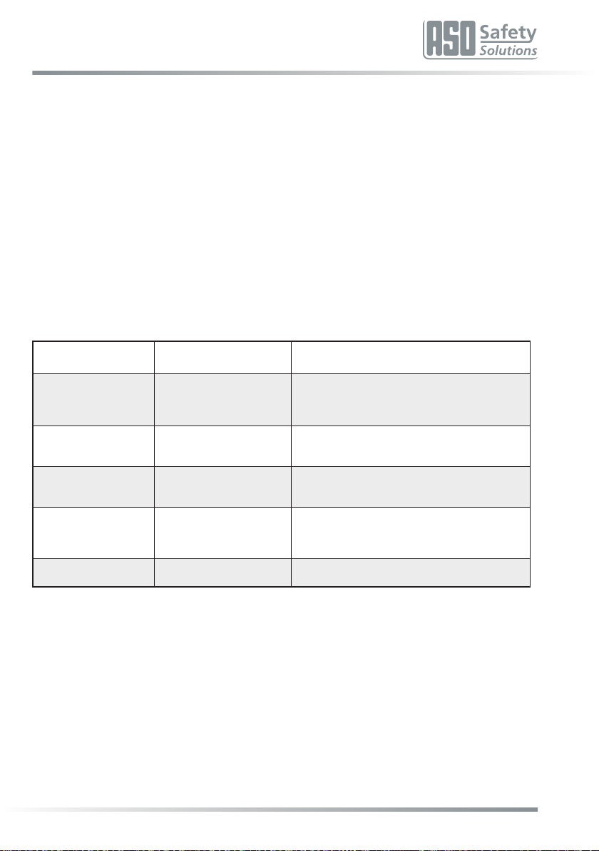
LED Fault Faultremoval
greenPower LED
doesnotlightup
Supplyvoltageismissing,
toolowor
incorrectlyconnected.
Checkconneconsandsupplyvoltage:
-230VAC(or120V)atterminalsA1 A2or
-24VAC/DCatterminalsB1 B2
Tolerancerange:±10%
greenPower LED
ashescyclically
(pulseoutput)
Internalfaultisindicated
bythenumberofpulses. See->signaldisplays
redCH1 LED
lightsup
Thecorrespondingsensor
isrecognized
asbeingoperated.
-Checktheconneconsofthecorrespondingsensors
(squeezedorbrilesupplylines,etc.)
-Checksignalsensor*
redCH1 LED
fastashing
Sensorcircuitinterrupted,
sensornotconnected,
defecvelyconnectedor
defecve.
-Checktheconneconsofthecorrespondingsensors
(squeezedorbrilesupplylines,etc.)
-Checksignalsensor*
redCH1 LED
slowashing Faultself-retaining Carryoutmanualreset
* Ifthefaultisnotfoundinthewiring,thefunconoftheelectronicsystemcanbecheckedbyapplying
aresistanceof8.2kΩtothesensor-inputontheswitchingdevice.Subsequently,iftheelectronicswork
perfectly,the sensormustbecheckedbymeansofan ohmmeter.Forthis purpose, theconneconof
thesensortotheswitchingdevicemustbeseparatedandconnectedbymeansofanohmmeter.Inthe
caseof a non-operatedsensor the resistancemustbe 8.2 kΩ ± 500 Ω. If the sensor is operated,the
resistancemustnotexceed500Ω.
12.Decommissioninganddisposal
TheproductsmanufacturedbyASOareexclusivelyintendedforcommercialuse(B2B).Attheendofuse,the
productsmustbedisposedofaccordingtoalllocal,regionalandnaonalregulaons.ASOisalsohappyto
takebacktheproductsanddisposesofthemproperly.
14
Safety Relay
13.Technicaldata
Mainsvoltage UNetz ELMONrelay41-822:120VAC±10%50/60Hz
ELMONrelay41-322:230VAC±10%50/60Hz
Lowvoltage UE24VAC/DC±10%
Power
consumpon
PNetz_
max
3,5VA230VAC
3,8VA120VAC50Hz/3,5VA120VAC60Hz
PE_max 1,5W24VDC
PE_max 1,2VA24VAC
FuseMainsvoltage
(external) 200mAmiddleme-lagfuse(glasstube5x20)
FuseLowvoltage
(external) 200mAmiddleme-lagfuse(glasstube5x20)
Nominalvalue RNom =8,2kΩ
upperswitchingvalue RAO >12,0kΩ
lowerswitchingvalue RAU <5,0kΩ
Supplyvoltage Terminangresistor–sensor
NominalcurrentDC 1A(24VDC)
NominalcurrentAC 1A(230VAC)
Mechanicalservicelife >106operaons
Switch-odelay
(reaconme) <11ms
Switch-ondelay ≤550ms(Poweron<850ms)
Ulizaoncategory AC-15(230VAC;1A;800000Op.)
DC-13(24VDC;1A;950000Op.)
Protecon 1Amiddleme-lagfuse(glass
tube5x20)
Safetyrelay
Max.switchingcurrent 2A(24VAC/DC)
Mechanicalservicelife >106operaons
OperangmodeRL:
Switch-ondelay 0,5Sek.
OperangmodeRL:
Switch-onduraon 3sec.
Signal relay
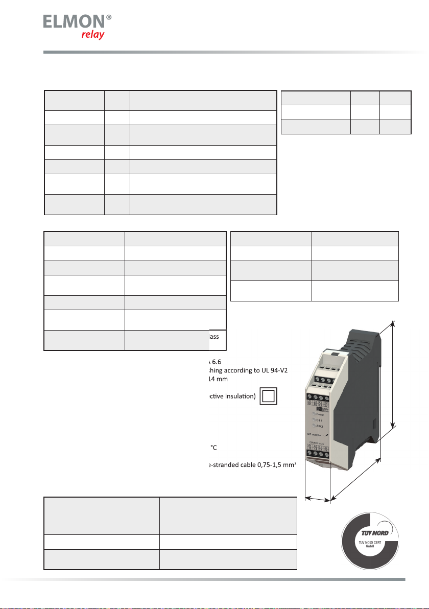
Housing PolyamidePA6.6
Self-exnguishingaccordingtoUL94-V2
Dimensions(HxWxD) 99x22,5x114mm
Protecontype IP20
Protecon classII(protecveinsulaon)
PolluonDegree 2
Overvoltagecategory III
Ratedinsulaonvoltage 250V
Ratedimpulsevoltageresistance 4,00kV
Weight 210g
Temperaturerangesinglemounng -20°Cto+55°C
Temperaturerangemounnginrow max.+35°C
Conneconcablecross-secon single-orne-strandedcable0,75-1,5mm2
Temperatureclasscopperconductors 60/75°C
ELMONrelay41-822(41-322)
ENISO13849-1:2015Category3PLe
(MTTFD195years,DC99%)
EN62061:2013SILCL3
(PFHd6,51E-091/h)
Electronics MTTFD625years,DC99%
Electromechanics B10D500000
MTTFD285years,DC99%(Nop17520)
Cercaons
WiththeRLUversion,thesignalrelayswitchessynchronously
totheoperaonofthesignaltransmier.
1Amiddleme-lagfuse(glass1Amiddleme-lagfuse(glass
Housing PolyamidePA6.6
Self-exnguishingaccordingtoUL94-V2
Dimensions(HxWxD) 99x22,5x114mm
Protecon classII(protecveinsulaon)
Temperaturerangesinglemounng -20°Cto+55°C
Conneconcablecross-secon single-orne-strandedcable0,75-1,5mm
2
114
22,5
99

ELMON relay 41-322 / 41-822
SafetyRelay
15
14.WarningsandDisclaimers
Readthisdocumentandthedocumentslistedintheaddionalresourcesseconaboutinstallaon,congu-
raon,andoperaonofthisequipmentbeforeyouinstall,congure,operate,ormaintainthisproduct.Users
arerequiredtofamiliarizethemselveswithinstallaonandwiringinstruconsinaddiontorequirementsof
allapplicablecodes,laws,andstandards.
Acviesincludinginstallaon,adjustments,pungintoservice,use,assembly,disassembly,andmain-
tenancearerequiredtobecarriedoutbysuitablytrainedpersonnelinaccordancewithapplicablecodeof
pracce.
Ifthisequipmentisusedinamannernotspeciedbythemanufacturer,theproteconprovidedbythe
equipmentmaybeimpaired.
Innoeventwillthemanufacturerberesponsibleorliableforindirectorconsequenaldamagesresulng
fromtheuseorapplicaonofthisequipment.
Theexamplesanddiagramsinthismanualareincludedsolelyforillustravepurposes.Becauseofthemany
variablesandrequirementsassociatedwithanyparcularinstallaon,themanufacturercannotassume
responsibilityorliabilityforactualusebasedontheexamplesanddiagrams.
Nopatentliabilityisassumedbythemanufacturerwithrespecttouseofinformaon,circuits,equipment,or
sowaredescribedinthismanual.
Beyondthat,thecurrentversionofASO’sGeneralTermsandCondionsshallapply.

16
Safety Relay
15.ECdeclaraonofconformity
Weherebydeclarethatthefollowingproductsoftheseries:
ELMON relay 41-322
(arclenumber1114-0030,
formatserialnumberyymmnnnnn
)
ELMON
relay 41-822
(
arclenumber
1114-0040,formatserialnumberyymmnnnnn)
Safety switching device for the combinaon of switching edges, switching mats and
switching bumpers for avoiding hazards at crush and shear locaons corresponds to
therelevantbasicsafetyandhealthrequirementsofthefollowingECDirecvesasa
resultofitsconceponandconstruconaswellasthedesignweputonthemarket:
MachineDirecve2006/42/EC
ENISO13849-1:2015
ENISO13849-2:2013-2
EN62061:2013-09
EN60947-5-1:2010-04
EN61000-6-2:2005
EN61000-6-3:2007
EC-typeapproval
NoedBody0044
TÜVNORDCERTGmbH
Langemarckstraße20
D-45141Essen
ECtype-examinaonno.:4420513031827
This declaraon of conformity does not absolve the machine designer/manufacturer of
hisobligaontoguaranteetheconformityoftheoverallmachinetowhichthisproductis
aachedinaccordancewiththeECDirecve
.
Manufacturerandauthorizedrepresentavefordocuments:
ASO,Antriebs-undSteuerungstechnikGmbH,
Hansastraße52,D59557Lippstadt

17
. . . . . . . . . . . . . . . . . . . . . . . . . . . . . . . . . . . . . . .
. . . . . . . . . . . . . . . . . . . . . . . . . . . . . . . . . . . . . . .
. . . . . . . . . . . . . . . . . . . . . . . . . . . . . . . . . . . . . . .
. . . . . . . . . . . . . . . . . . . . . . . . . . . . . . . . . . . . . . .
. . . . . . . . . . . . . . . . . . . . . . . . . . . . . . . . . . . . . . .
. . . . . . . . . . . . . . . . . . . . . . . . . . . . . . . . . . . . . . .
. . . . . . . . . . . . . . . . . . . . . . . . . . . . . . . . . . . . . . .
. . . . . . . . . . . . . . . . . . . . . . . . . . . . . . . . . . . . . . .
. . . . . . . . . . . . . . . . . . . . . . . . . . . . . . . . . . . . . . .
. . . . . . . . . . . . . . . . . . . . . . . . . . . . . . . . . . . . . . .
. . . . . . . . . . . . . . . . . . . . . . . . . . . . . . . . . . . . . . .
. . . . . . . . . . . . . . . . . . . . . . . . . . . . . . . . . . . . . . .
. . . . . . . . . . . . . . . . . . . . . . . . . . . . . . . . . . . . . . .
. . . . . . . . . . . . . . . . . . . . . . . . . . . . . . . . . . . . . . .
. . . . . . . . . . . . . . . . . . . . . . . . . . . . . . . . . . . . . . .
. . . . . . . . . . . . . . . . . . . . . . . . . . . . . . . . . . . . . . .
. . . . . . . . . . . . . . . . . . . . . . . . . . . . . . . . . . . . . . .
. . . . . . . . . . . . . . . . . . . . . . . . . . . . . . . . . . . . . . .
. . . . . . . . . . . . . . . . . . . . . . . . . . . . . . . . . . . . . . .
. . . . . . . . . . . . . . . . . . . . . . . . . . . . . . . . . . . . . . .
. . . . . . . . . . . . . . . . . . . . . . . . . . . . . . . . . . . . . . .
. . . . . . . . . . . . . . . . . . . . . . . . . . . . . . . . . . . . . . .
Notes
ELMON relay 41-822 / 41-322
Safety Relay

18
. . . . . . . . . . . . . . . . . . . . . . . . . . . . . . . . . . . . . . .
. . . . . . . . . . . . . . . . . . . . . . . . . . . . . . . . . . . . . . .
. . . . . . . . . . . . . . . . . . . . . . . . . . . . . . . . . . . . . . .
. . . . . . . . . . . . . . . . . . . . . . . . . . . . . . . . . . . . . . .
. . . . . . . . . . . . . . . . . . . . . . . . . . . . . . . . . . . . . . .
. . . . . . . . . . . . . . . . . . . . . . . . . . . . . . . . . . . . . . .
. . . . . . . . . . . . . . . . . . . . . . . . . . . . . . . . . . . . . . .
. . . . . . . . . . . . . . . . . . . . . . . . . . . . . . . . . . . . . . .
. . . . . . . . . . . . . . . . . . . . . . . . . . . . . . . . . . . . . . .
. . . . . . . . . . . . . . . . . . . . . . . . . . . . . . . . . . . . . . .
. . . . . . . . . . . . . . . . . . . . . . . . . . . . . . . . . . . . . . .
. . . . . . . . . . . . . . . . . . . . . . . . . . . . . . . . . . . . . . .
. . . . . . . . . . . . . . . . . . . . . . . . . . . . . . . . . . . . . . .
. . . . . . . . . . . . . . . . . . . . . . . . . . . . . . . . . . . . . . .
. . . . . . . . . . . . . . . . . . . . . . . . . . . . . . . . . . . . . . .
. . . . . . . . . . . . . . . . . . . . . . . . . . . . . . . . . . . . . . .
. . . . . . . . . . . . . . . . . . . . . . . . . . . . . . . . . . . . . . .
. . . . . . . . . . . . . . . . . . . . . . . . . . . . . . . . . . . . . . .
. . . . . . . . . . . . . . . . . . . . . . . . . . . . . . . . . . . . . . .
. . . . . . . . . . . . . . . . . . . . . . . . . . . . . . . . . . . . . . .
. . . . . . . . . . . . . . . . . . . . . . . . . . . . . . . . . . . . . . .
. . . . . . . . . . . . . . . . . . . . . . . . . . . . . . . . . . . . . . .
Notes
Safety Relay

19
. . . . . . . . . . . . . . . . . . . . . . . . . . . . . . . . . . . . . . .
. . . . . . . . . . . . . . . . . . . . . . . . . . . . . . . . . . . . . . .
. . . . . . . . . . . . . . . . . . . . . . . . . . . . . . . . . . . . . . .
. . . . . . . . . . . . . . . . . . . . . . . . . . . . . . . . . . . . . . .
. . . . . . . . . . . . . . . . . . . . . . . . . . . . . . . . . . . . . . .
. . . . . . . . . . . . . . . . . . . . . . . . . . . . . . . . . . . . . . .
. . . . . . . . . . . . . . . . . . . . . . . . . . . . . . . . . . . . . . .
. . . . . . . . . . . . . . . . . . . . . . . . . . . . . . . . . . . . . . .
. . . . . . . . . . . . . . . . . . . . . . . . . . . . . . . . . . . . . . .
. . . . . . . . . . . . . . . . . . . . . . . . . . . . . . . . . . . . . . .
. . . . . . . . . . . . . . . . . . . . . . . . . . . . . . . . . . . . . . .
. . . . . . . . . . . . . . . . . . . . . . . . . . . . . . . . . . . . . . .
. . . . . . . . . . . . . . . . . . . . . . . . . . . . . . . . . . . . . . .
. . . . . . . . . . . . . . . . . . . . . . . . . . . . . . . . . . . . . . .
. . . . . . . . . . . . . . . . . . . . . . . . . . . . . . . . . . . . . . .
. . . . . . . . . . . . . . . . . . . . . . . . . . . . . . . . . . . . . . .
. . . . . . . . . . . . . . . . . . . . . . . . . . . . . . . . . . . . . . .
. . . . . . . . . . . . . . . . . . . . . . . . . . . . . . . . . . . . . . .
. . . . . . . . . . . . . . . . . . . . . . . . . . . . . . . . . . . . . . .
. . . . . . . . . . . . . . . . . . . . . . . . . . . . . . . . . . . . . . .
. . . . . . . . . . . . . . . . . . . . . . . . . . . . . . . . . . . . . . .
. . . . . . . . . . . . . . . . . . . . . . . . . . . . . . . . . . . . . . .
Notes
ELMON relay 41-822 / 41-322
Safety Relay

20
11.DB.17.004 Operang Manual Rev 04
Subject to technical modicaons.
No liability can be assumed for errors or misprints.
This operang manual is valid for the following versions:
from V 1.0 to V 5.1
English
Safety Relay
ASO Safety Soluons Inc.
300 Roundhill Drive, Unit 6 • Rockaway. NJ 07866
Phone: +1 973 586 9600 • Fax: +1 973 784 4994
www.asosafety.com • e-mail: sales-us@asosafety.com
This manual suits for next models
1
Table of contents
Other ASO Relay manuals


