ASO ISK 71?24 User manual

ISK 71-24
ISK 71-94
11
10
9
87654
3
2
1
TransmitOpening
StationaryOpening
Transmit
Stationary
Power
ISK71‑24
D‑33154Salzkotten
www.asosafety.comTÜV‑NORD
CERT
11
10
9
87654
3
2
1
TransmitOpening
StationaryOpening
Transmit
Stationary
Power
ISK71‑94
D‑33154Salzkotten
www.asosafety.comTÜV‑NORD
CERT
Betriebsanleitung (Original)
ISK 71‑24 + ISK 71‑94 Induktives Sicherheitsschaltgerät
Deutsch
Seite 3‑11
Manuel d’utilisation
ISK 71‑24 + ISK 71‑94
Relais de s�curit� à inductionde s�curit� à inductionà induction
Operating Manual
ISK 71‑24 + ISK 71‑94
Inductive Safety RelayRelay
EnglishFrançais
Page 13‑21
Page 23‑31
Manuale di istruzione
ISK 71‑24 + ISK 71‑94 Sistema di sicurezza induttivo
Italiano
Pagina 33‑41
Gebruiksaanwijzing
ISK 71‑24 + ISK 71‑94 Inductief Veiligheidsschakelrelais
Nederlands
Pagina 43‑51

2
Übergabedokumentation / Documentation / Documentation
de datation / Documentazione di consegna / Documentatie
Anlagenbeschreibung / Description / Description du système / Descrizione impianto /
Beschrijving van de installatie
Anlagenart / Type of plant / Sorte du système / Tipo d’impianto / Type installatie
Hersteller / Manufacturer / Fabricant / Produttore / Fabrikant
Seriennummer / Serial number / Num�ro de s�rie / Numero di serie / Seriennummer
Datum der Inbetriebnahme / Commissioning date / Date de mise en marche / Data della messa in
funzione / Datum van de ingebruikname
Aufstellort / Site of installation / Lieu de montage / Luogo d’installazione / Opstellingsplaats
Verwendete Steuerung / Control unit / Commande utilis�e / Centralina di comando adottata /
Gebruikte besturing
Zusatzkomponenten / Additional components / Composants suppl�mentaires / Componenti
ausiliari / Bijkomende componenten
Funktionsprüfung / Functional test / Contrôle de fonction / Controllo funzionale / Functiecontrole
Sicherheitssensoren reagieren auf Betätigung / Safety sensor response to actuation /
Le senseur de s�curit� r�agit à l’actionnement / Il sensore di sicurezza reagisce all’azionamento /
Veiligheidssensor reageert op activering
Sicherheitssensoren reagieren auf Zuleitungsunterbrechung / Safety sensor response to
supply line interruption / Le senseur de s�curit� r�agit à l’interruption de l’alimentation /
Il sensore di sicurezza reagisce all’interruzione di collegamento Veiligheidssensor reageert
op onderbreking van de toevoerleiding
ok
Name der ausführenden Firma / Owner / Nom de la soci�t� ex�cutrice / Nome della ditta
esecutrice / Naam van de uitvoerende rma
Name des Installateurs / Installer / Nom de l’installateur / Nome dell’installatore / Naam van de
installateur
Datum / Date / Date / Data / Datum Unterschrift / Signature / Signature / Firma /
Handtekening
ok

3
Deutsch
1. Inhaltsverzeichnis
ISK 71-24 + ISK 71-94
Induktives Sicherheitsschaltgerät
Technische und betriebsrelevante Änderungen zu den in dieser Doku-
mentation aufgeführten Produkten und Geräten sind jederzeit auch ohne
Vorankündigung vorbehalten.
1. Inhaltsverzeichnis . . . . . . . . . . . . . . . . . . 3
2. Allgemeine Sicherheitsbestimmungen und
Schutzmaßnahmen . . . . . . . . . . . . . . . . . 4
3. Allgemeines . . . . . . . . . . . . . . . . . . . . . 5
4. Funktion . . . . . . . . . . . . . . . . . . . . . . . 5
5. Bestimmungsgemäße Verwendung . . . . . . . . . 5
6. Systemkomponenten am Tor . . . . . . . . . . . . 6
7. Geräteübersicht . . . . . . . . . . . . . . . . . . . 6
7.1 Signalanzeigen . . . . . . . . . . . . . . . . . . . . . . 6
7.2 Anschlussklemmen . . . . . . . . . . . . . . . . . . . . 6
8. Anschluss des Gerätes . . . . . . . . . . . . . . . 7
8.1 Voraussetzungen.1 Voraussetzungen . . . . . . . . . . . . . . . . . . . . . 7
8.2 Versorgungsspannung.2 Versorgungsspannung . . . . . . . . . . . . . . . . . . 7
8.3 Anschluss ortsfester Spulenkern . . . . . . . . . . . . . 7
8.4 Anschluss stationäre Kontaktleisten . . . . . . . . . . . 7
8.5 Anschluss Steuerstromkreise . . . . . . . . . . . . . . . 7
9. Anschließen der mitfahrenden Signalgeber. . . . . 8
9.1 Anschluss am mitfahrenden Spulenkern . . . . . . . . . 8
9.2.2
Anschluss mehrerer Signalgebern pro Signalgeberkreis
. . 8
10.
Inbetriebnahme und Funktionsprüfung
. . . . . . . . 8
11. Fehlerdiagnose . . . . . . . . . . . . . . . . . . . 9
12. Außerbetriebnahme und Entsorgung . . . . . . . . 10
13. Technische Daten . . . . . . . . . . . . . . . . . . 10
14. EG Konformitätserklärung. . . . . . . . . . . . . . 11

4
ISK 71-24 + ISK 71-94 Induktives Sicherheitsschaltgerät
Deutsch
2. Allgemeine Sicherheitsbestimmungen und Schutzmaßnahmen
• Hersteller und Benutzer der Anlage / Maschine, an der die Schutzeinrichtung verwendet wird,
sind dafür verantwortlich, alle geltenden Sicherheitsvorschriften und ‑regeln in eigener Verant‑
wortung abzustimmen und einzuhalten.
• Die Schutzeinrichtung garantiert in Verbindung mit der übergeordneten Steuerung eine funktio‑
nale Sicherheit, nicht aber die Sicherheit der gesamten Anlage / Maschine. Vor dem Einsatz des
Gerätes ist deshalb eine Sicherheitsbetrachtung der gesamten Anlage / Maschine nach der
Maschinenrichtlinie 98/37 EG oder nach entsprechender Produktnorm notwendig.
• Die Bedienungsanleitung muss ständig am Einsatzort der Schutzeinrichtung verfügbar sein.
Sie ist von jeder Person, die mit der Bedienung, Wartung oder Instandhaltung der Schutzein‑
richtung beauftragt wird, gründlich zu lesen und anzuwenden.
• Die Installation und Inbetriebnahme der Schutzeinrichtung darf nur durch Fachpersonal
erfolgen, die mit dieser Betriebsanleitung und den geltenden Vorschriften über Arbeitssicherheit
und Unfallverhütung vertraut sind. Die Hinweise in dieser Anleitung sind unbedingt zu beachten
und einzuhalten.
Elektrische Arbeiten dürfen nur von Elektrofachkräften durchgeführt werden.
• Sicherheitsvorschriften der Elektrotechnik und der Berufsgenossenschaft sind zu beachten.
• Bei Arbeiten am Schaltgerät ist dieses spannungsfrei zu schalten, auf Spannungsfreiheit zu
prüfen und gegen Wiedereinschalten zu sichern.
• Werden die potentialfreien Kontakte der Relaisausgänge mit einer gefährlichen Spannung fremd‑
gespeist, ist sicherzustellen, dass diese bei Arbeiten an dem Schaltgerät ebenfalls abge‑
schaltet werden.
• Das Schaltgerät enthält keine vom Anwender zu wartende Bauteile. Durch eigenmächtige
Umbauten bzw. Reparaturen am Schaltgerät erlischt jegliche Gewährleistung und Haftung des
Herstellers.
• Das Schutzsystem ist in geeigneten Zeitabständen von Sachkundigen zu prüfen und in jederzeit
nachvollziehbarer Weise zu dokumentieren.
Sicherheitshinweise
• Das Schaltgerät ermöglicht den Betrieb an 24 V AC/DC. Der Anschluss der Betriebsspannung an
die falschen Klemmen kann das Schaltgerät zerstören.
• Das Schaltgerät ist in einem Schaltschrank zu montieren.
• Nicht in unmittelbarer Nähe von starken Wärmequellen montieren.
• Bei kapazitiven und induktiven Verbrauchern ist für eine ausreichende Schutzbeschaltung zu
sorgen.
Das Schaltgerät ist nach EN 954-1 „Sicherheitsbezogene Teile von Steuerungen“ für
Kat. 3 ausgelegt. Zur Einhaltung der Kat. 3 ist das Schaltgerät redundant, mit zwei sich
gegenseitig abfragenden, zwangsgeführten Sicherheitsrelais pro Kanal aufgebaut.
Die Anforderungen der Tornormen EN 12978 „Schutzeinrichtungen für kraftbetätigte Türen
und Tore“ und EN 12453 „Nutzungssicherheit kraftbetätigter Tore“ werden ebenfalls erfüllt.
Bei Nichtbeachtung oder vorsätzlichem Missbrauch entfällt die Haftung des Herstellers.

5
Deutsch
3. Allgemeines
Das Seilübertragungssystem ISK löst die Problematik, bewegliche Signalgeber mit einer stationären
Auswertung ohne mechanische Belastung zu verbinden. Die Kommunikation zwischen den
beweglichen Signalgebern und der Auswertelektronik beruht hierbei auf induktiver Basis. Die Über‑
wachungselektronik induziert hierfür eine Frequenz auf einen Spulenkern, der in eine geschlossene
Leiterschleife eingebunden ist.
Der zweite Spulenkern, an dem die beweglichen Signalgeber angeschlossen sind, empfängt diese
Frequenz und gibt bei Kabelbruch oder bei Betätigung eines Signalgebers eine entsprechende
Rückmeldung an die Auswertelektronik.
4. Funktion
Das kompakte und montagefreundliche Sicherheitsschaltgerät ist für den Einsatz im Schaltschrank
ausgelegt, wo eine 24 V Versorgungsspannung zur Verfügung steht.
An das Schaltgerät können bis zu vier Sicherheitskontaktleistenkreise angeschlossen werden. Für
die Sicherheitskontaktleisten (SKL) am Torblatt stehen zwei Kanäle (SKL Auf‑Bewegung und SKL
Zu‑Bewegung), und für die Sicherheitskontaktleisten am Führungspfosten ebenfalls zwei Kanäle
zur Verfügung. Die beweglichen, am Torblatt mitfahrenden Sicherheitskontaktleisten werden durch
das Seilübertragungssystem berührungslos und verschleißfrei überwacht. Die ortsfesten Sicher‑
heitskontaktleisten werden direkt an das Schaltgerät angeschlossen.
Das Schaltgerät überwacht diese vier Sicherheitskontaktleistenkreise permanent auf Betätigung
oder Unterbrechung (Kabelbruch). Bei einer Störung wird dem entsprechenden Sicherheitskon‑
taktleistenkreis einem der zwei Stop‑Befehle zugeordnet (Stop in Auf‑Richtung oder Stop in Zu‑
Richtung). Um eine Ruhestromüberwachung des gesamten Systems zu ermöglichen, ist in die
Endleiste des jeweilige Sicherheitskontaktleistenkreises ein Abschlusswiderstand integriert. Fließt
der Soll‑Ruhestrom, so sind die Ausgangsrelais angesteuert und die Schaltkontakte geschlossen.
Wird das Schaltelement betätigt oder der Signalgeberstromkreis unterbrochen, öffnen die Relais‑
Schaltkontakte.
Die Schaltzustände der Relais und die angelegte Betriebsspannung werden durch LED‘s ange‑
zeigt.
5. Bestimmungsgemäße Verwendung
Das Sicherheitsübertragungssystem ISK 71‑24 ist ausgelegt für die Auswertung von stationären und
mitfahrenden Sicherheitskontaktleisten mit konstantem 8,2KWWiderstand.
Ein anderer oder darüber hinausgehender Einsatz ist nicht bestimmungsgemäß. Für Schäden, die aus
nicht bestimmungsgemäßen Verwendungen entstehen, übernimmt der Hersteller keine Haftung.
Der Einsatz bei Sonderanwendungen bedarf einer Freigabe vom Hersteller.

6
ISK71‑24
TransmitOpening
StationaryOpening
Transmit
Stationary
Power
ISK71‑24
33 11 10 1 2
22 2
Deutsch
6. Systemkomponenten am Tor
243
1
Tor öffnet Tor schließt
SKL AUF Bewegung
SKL AUF Bewegung
SKL AUF Bewegung
SKL ZU Bewegung
SKL ZU Bewegung
SKL ZU Bewegung
ISK 71-24 + ISK 71-94 Induktives Sicherheitsschaltgerät
Stationary Op.
Transm it
Stationary Cl.
Se rial N o.: 0 9 2 0 0 7 0 0 0 0 0
ISK 71‑94 V5.1
87654
9
10 11 1 2
3
Power
Transmit Op en ing
Statio nary Openin g
Transmit Closing
Statio nary Clos ing
ISK 71-24
Power
Transmit Op en ing
Statio nary Openin g
Transmit Closing
Statio nary Clos ing
ISK 71-94
ISK 71-24 ISK 71-94
Unterseite
1 Steuergerät ISK 71‑24 (ISK 71‑94)
2 Feststehender Spulenkern
3 Mitfahrender Spulenkern
4 Stahlseil als Übertragungsmedium
Applikationsbeispiel
DieAnordnung der einzelnen Komponenten ist
abhängig von der jeweiligen Torkonstruktion
und von baulichen Gegebenheiten.
7. Geräteübersicht
7.1 Signalanzeigen
LED Power grün
Versorgungsspannung
LED Transmit Opening rot
Störung Auf‑Bewegung mitfahrende Leiste(n)
LED Stationary Opening rot
Störung Auf‑Bewegung stationäre Leiste(n)
LED Transmit Closing rot
Störung Zu‑Bewegung mitfahrende Leiste(n)
LED Stationary Closing rot
Störung Zu‑Bewegung stationäre Leiste(n)
7.2 Anschlussklemmen
ISK 71-94
Transmit
Stationary Op.
Stationary Cl.
Pin 4, 5
Pin 6, 7
Pin 8, 9
ISK 71-24
Pin 1, 2 feststehender Spulenkern
Pin 3, 11 SKL Führungspfosten Öffnen
Pin 3, 10 SKL Führungspfosten Schliessen
Pin 4, 5 Relais‑Ausgang zur Steuerung Stop Öffnen
Pin 6, 7 Relais‑Ausgang zur Steuerung Stop Schliessen
Pin 8, 9 Versorgungsspannung 24 V

7
Deutsch
11
10
9
8
7654
3
2
1
9
8
2
1
7654
11
103
%%
‑+24V AC/DC
11
103
7654
8
2
1
9
7654
8
11
103
2
1
9
11
10
9
8
7654
3
2
1
%%
‑+24V AC/DC
7654
8
11
103
2
1
9
ISK 71-24 ISK 71-94
StationaryOp.
Transmit
StationaryCl.
Power
TransmitOpening
StationaryOpening
TransmitClosing
StationaryClosing
ISK71-94
SerialNo.:09200700000
ISK 71‑94V5.1
S ta t io n . O p.
T r a n s m it
S t a t i o n . C l.
c l o s i n g d ir e ct io n
o p e n in g d i r e c t io n
c l o s i n g d ir e ct io n
o p e n in g d ir e ct io n
8,2
kO
h
m8
,2
kO
h
m
8
,2kO
h
m8
,2kO
h
m
s
te
e
lro
p
e
tran
sm
iss
io
n
co
il
fixe
d
tra
n
s
m
iss
io
n
c
o
il
tra
v
ellin
g
T e c h n i c a l d a t a :
U = 2 4 V A C / D C
I = 1 0 0 m A
P = 2 , 4 W
StationaryOp.
Transmit
StationaryCl.
Power
TransmitOpening
StationaryOpening
TransmitClosing
StationaryClosing
ISK71-94
SerialNo.:09200700000
ISK 71‑94V5.1
S ta t io n . O p.
T r a n s m it
S ta t io n . C l.
c l o s i n g d ir e ct io n
o p e n in g d ir e c ti o n
c lo s i n g d i r ec t io n
o p e n in g d ir e ct io n
8,2
kO
h
m8
,2
kO
h
m
8
,2kO
h
m8
,2kO
h
m
s
te
e
lro
p
e
tran
sm
iss
io
n
co
il
fixe
d
tra
n
s
m
iss
io
n
c
o
il
tra
v
ellin
g
T e c h n i c a l d a t a :
U = 2 4 V A C / D C
I = 1 0 0 m A
P = 2 , 4 W
8.2 Versorgungsspannung.2 Versorgungsspannung
Als Spannungsversorgung ist bei der ISK 71‑24 und der ISK 71‑94
an dem Klemmenpaar 8, 9 24V AC/DC anzuschließen.
8.3 Anschluss ortsfester Spulenkern
ISK 71-24: An das Klemmenpaar 1, 2 ist der ortsfeste Spulenkern
anzuschließen,
wobei die Polarität beliebig ist.
ISK 71-94: Der ortsfeste Spulenkern ist mit dem Steck
platz
Transmit zu verbinden.
Der Anschluss am Spulenkern erfolgt über die mitgelieferten
Quetschverbinder oder durch direktes Anlöten der Leitung an die
Stecker.
8.4 Anschluss stationäre Kontaktleisten
ISK 71-24: Die stationäre(n) Sicherheitskontaktleiste(n) (SKL)
am
Führungspfosten für die Auf‑Bewegung wird (werden) an
das
Klemmenpaar 3, 11 angeschlossen.
ISK 71-94: Die stationäre(n) SKL für die Auf‑Bewegung wird
(werden) mit dem Steckplatz Stationary Opening verbunden
.
Bei mehreren SKL werden diese in Reihe geschaltet und die
Endleiste mit 8,2 kWabgeschlossen.
ISK 71-24:
Die stationäre(n) SKL für die Zu‑Bewegung wird (werden)
an das Klemmenpaar 3, 10 angeschlossen.
ISK 71-94: Die stationäre(n) SKL für die Zu‑Bewegung wird (werden
)
mit dem Steckplatz Stationary Closing verbunden.
Sollte ein Kanal für die stationären SKL oder eventuell beide
Kanäle nicht genutzt werden, sind die Kanäle mit den mitge-
lieferten 8,2 kWWiderständen zu belegen.
8.5 Anschluss Steuerstromkreise
An das Klemmenpaar 4, 5 ist der zu überwachende Steuerstrom‑
kreis für die Auf‑Bewegung (Stop‑Auf‑Bewegung) und an das
Klemmenpaar 6, 7 der entsprechende Steuerstromkreis für die
Zu‑Bewegung (Stop‑Zu‑Bewegung) anzuschließen.
8. Anschluss des Gerätes
8.1 Voraussetzungen.1 Voraussetzungen
• Die Versorgungsspannung des ISK 71‑24 muss denAnforderungen für Schutzkleinspannung (SELV)
entsprechen.
• Leitungen, die im Freien oder außerhalb vom Schaltschrank verlegt werden, müssen entsprechend
geschützt werden.
• Die für das Gerät angegebene Schutzart ist nur dann sichergestellt, wenn die Zuleitungen
ordnungsgemäß in die Verschraubungen geklemmt sind.

8
Deutsch
ISK 71-24 + ISK 71-94 Induktives Sicherheitsschaltgerät
ASO-Signalgeber dürfen nicht parallel geschaltet werden.
Bild 1: Verschaltung am Spulenkern
SKL
ZU-Bewegung
SKL
AUF-Bewegung
OC
10. Inbetriebnahme / Funktionsprüfung
Nach entsprechendem Anschluss aller elektrischen Verbindungen und Einschalten der Versorgungs‑
spannung, muss die Toranlage auf korrekte Funktion überprüft werden. Hierzu sind alle Sicherheits‑
kontaktleisten der Reihe nach zu betätigen und die entsprechenden Reaktionen des Schaltgerätes
zu kontrollieren.
9. Anschließen der Signalgeber
9.1 Anschluss am Spulenkern (Bild 1)
9.2 Anschluss von mehreren Signalgebern pro Signalgeberkreis (Bild 2)
An dem Signalgebereingang Obzw. Ckönnen ein oder mehrere Signalgeber angeschlossen
werden. Hierfür werden die einzelnen Signalgeber entsprechend Bild 2 in Serie geschaltet.
Maximal können 5 Signalgeber mit einer Gesamtkabellänge von max. 25 m in Serie geschaltet werden.
Die Länge eines Signalgebers kann bis zu 25 m betragen.
Vor dem Anschließen der in Serie geschalteten Signalgeber ist es empfehlenswert, den Widerstands‑
wert der Verschaltung auszumessen.
Bei unbetätigter SKL muss der Widerstand 8,2 kW± 500 Wbetragen. Ist die SKL betätigt, darf der
Widerstand 500 Wnicht überschreiten.
Sollte ein Kanal nicht genutzt werden, muss dieser mit einem 8,2 kW Widerstand
belegt werden.
Die mitfahrenden Leisten (SKL) werden mit dem
mitfahrenden Spulenkern verbunden.
Hierzu wird die mitfahrende
SKL
ZU Bewegung mit
dem Anschluss Cdes mitfahrenden Spulenkerns
verbunden
und die optionale
SKL
AUF
Bewegung
mit dem Anschluss O
.
Der Anschluss der SKL am Spulenkern erfolgt über
die mitgelieferten Quetschverbinder oder durch
direktes Anlöten der Leitung an die Stecker.
Signalgeber 1 Signalgeber 2 Signalgeber „n“
2
222
O
C
Bild 2: Verschaltung mehrerer Signalgeber, hier am Beispiel Sicherheitskontaktleiste

9
Deutsch
11. Fehlerdiagnose
Bei korrekter Verdrahtung und Anlegen der Versorgungsspannung darf nur die grüne LED leuchten.
Bei Aueuchten einer der roten LED‘s ist ein Fehler im System vorhanden, der sich mit Hilfe der
LED eingrenzen lässt.
LED Fehler Fehlerbeseitigung
LED‘s
leuchten nicht
Versorgungsspannung fehlt, zu gering
oder falsch angeschlossen
Anschlüsse und Versorgungsspannung überprüfen:
‑ 24 V AC/DC an Klemmen 8 9
Toleranzbereich: ±10%
einzelne rote LED
leuchtet
Kontaktleiste(n) nicht angeschlossen,
fehlerhaft angeschlossen oder defekt
‑ Anschlüsse der entsprechenden Kontaktleiste
überprüfen (abgequetschte Zuleitungen, brüchige
Zuleitungen etc.)
‑ Sicherheitskontaktleiste(n) überprüfen*
Ein Kontaktleisten‑Anschluss wird nicht
benutzt
Nicht benutzte Kontaktleisten‑Anschlüsse dauerhaft
mit einem der mitgelieferten 8,2 kΩ-Widerstände
überbrücken
beide roten
Transmit LED‘s
leuchten
Übertragungsstrecke ist gestört oder
fehlerhaft montiert
‑ mech. Montageanleitung beachten (ISK Sicher‑
heitsübertragungsystem)
‑ Übertragungskerne auf Verschleiß überprüfen.
‑ Seilkreis überprüfen; hier ist darauf zu achten,
dass beide Übertragungskerne sich innerhalb des
Seilkreis benden
‑ Kontaktstellen Seil / Torkörper überprüfen.
‑ Versorgungsspannung überprüfen**
Kontaktleiste(n) nicht angeschlossen,
fehlerhaft angeschlossen oder defekt
‑ Anschlüsse der entsprechenden Kontaktleiste
überprüfen (abgequetschte Zuleitungen, brüchige
Zuleitungen etc.)
‑ Sicherheitskontaktleiste(n) überprüfen*
* Liegt der Fehler nicht in der Verdrahtung, kann die Funktion der Elektronik durch Belegung
aller SKL‑Eingänge an der ISK 71‑24 Auswertelektronik (Klemmen 3, 10 und Klemmen 3, 11)
und am
mitfahrenden
Spulenkern (Anschlüsse Ound C) mit jeweils einem 8,2 kWWiderstand
überprüft werden. Arbeitet danach die Elektronik einwandfrei, müssen die Sicherheitskontakt‑
leisten mit einem Widerstandsmessgerät überprüft werden. Hierfür muss die jeweilige Verbin‑
dung der SKL zur Auswertelektronik oder zum
mitfahrenden
Spulenkern aufgetrennt und mit
einem Widerstandsmessgerät verbunden werden.
Bei unbetätigter Sicherheitskontaktleiste muss der Widerstand 8,2 kW ±500 W betragen. Ist die
Sicherheitskontaktleiste betätigt, darf der Widerstand 500 W nicht überschreiten.
** Sollten die beiden LED’s für die mitfahrenden SKL (Transmit Opening und Transmit
Closing) leuchten, ist ein Fehler im induktiven Übertragungssystem vorhanden. Die
häufigsten Fehlerquellen hierfür sind schlechte Verbindungen an den Spulenkernen,
nicht ordnungsgemäß installierte Seilsystemkomponenten (siehe Montageanleitung ISK‑
Sicherheitsübertragungssystem) oder eine unzulässig niedrige Versorgungsspannung.
Die Seilschleife darf einen maximalen Widerstandswert von 3 W haben. Der Widerstandswert kann
durch Lösen des Stahlseiles von der Erdungsklemme und anschließendem Messen zwischen
Stahlseilende und Erdungsklemme ermittelt werden.
10
Deutsch
Zertikat Nr.: Prüfbericht Nr.:
78/780/551696 04/YTT551696
11
10
9
87654
3
2
1
TransmitOpening
StationaryOpening
Transmit
Stationary
Power
ISK71‑24
38
82
8426
ISK 71-24 + ISK 71-94 Induktives Sicherheitsschaltgerät
12. Außerbetriebnahme und Entsorgung
Die von ASO hergestellten Produkte sind ausschließlich für den gewerblichen Gebrauch (B2B)
vorgesehen. Nach Nutzungsbeendigung sind die Produkte gemäß allen örtlichen, regionalen und
nationalen Vorschriften zu entsorgen. ASO nimmt die Produkte auch gern zurück und entsorgt diese
ordnungsgemäß.
13. Technische Daten
Versorgungsspannung UE24 V AC/DC A10%
Leistungsaufnahme Pmax 3 VA
Zulassungen
Kategorie 3 nach EN 954‑1
Sicherheitseinrichtung nach EN 12978
Anschlusswiderstand Sicherheitskontaktleisten
Nominalwert Rnom = 8,2 kΩ
oberer Schaltwert RAO > 20 kΩ
unterer Schaltwert RAU < 2,5 kΩ
Relais Stufen
max. Schaltspannung 30 V ~ / 30 V ‑
max. Schaltstrom 5 A ~ / 5 A ‑
Mechanische Lebensdauer >106Betätigungen
Schaltzeiten Sicherheitsrelais
Reaktionszeit < 20 ms
Freischaltzeit > 500 ms
Montage
Stecksockel zur 35 mm DIN‑Schnappschienenmontage
Gehäuse
11 pol. DIN Stecksockelgehäuse mit Stecksockel für
35 mm Montageschiene
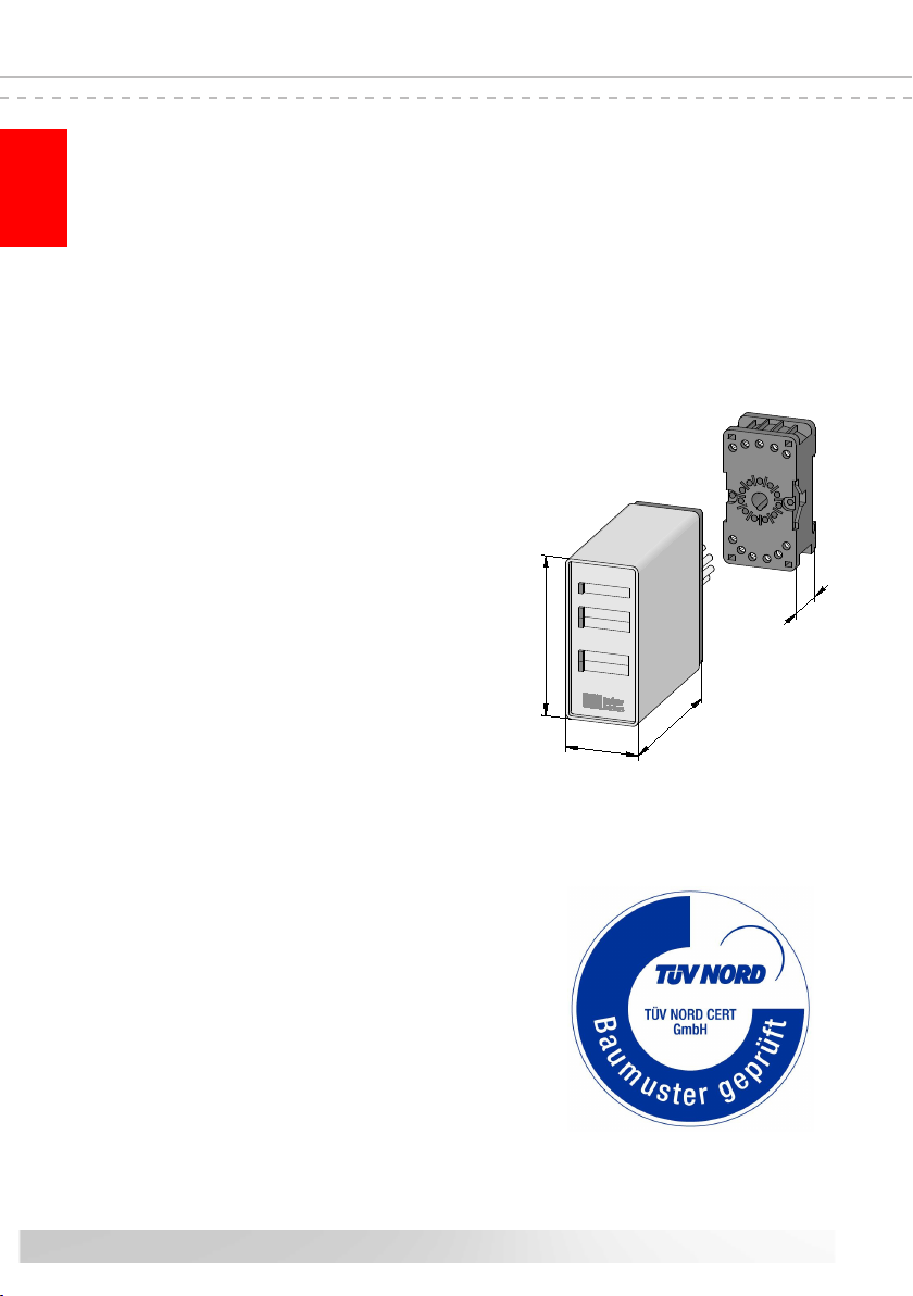
Abmessungen: (HxBxT)
Gehäuse 82 x 38 x 84 mm
Gehäuse incl. Stecksockel 82 x 38 x 110 mm
Schutzart IP20
Gewicht 225 g
Temperaturbereich ‑25°C bis +55°C
Querschnitt Anschlussleitungen
ein‑, oder feindrähtige Leitung 0,75‑1,5 mm2
Alle an das Schaltgerät angeschlossenen Spannungen
müssen sicher getrennte Spannungen sein!

11
Deutsch
14. EG Konformitätserklärung
Hiermit erklären wir, dass die nachfolgend bezeichneten Produkte der Baureihe:
ISK 71-24 (Artikelnummer 204600, Format Seriennummer yymmnnnnn)
ISK 71-94 (Artikelnummer 204610, Format Seriennummer yymmnnnnn)
Induktive Übertragungsvorrichtung mit Sicherheitsschaltsystem zur Kombina‑
tion mit Schaltleisten zur Vermeidung von Gefahren an Quetsch‑ und Scher‑
stellen bei Torsystemen aufgrund ihrer Konzipierung und Bauart sowie in der
von uns in Verkehr gebrachten Ausführung, den einschlägigen grundlegenden
Sicherheits‑ und Gesundheitsanforderungen der nachfolgenden EG‑Richtlinien
und Normen entspricht:
EG - Maschinenrichtlinie 2006/42/EG
EN 12978:2003
EN 954‑1:1996
EN 61000‑6‑2:2002
EN 61000‑6‑3:2002
EG - Baumusterprüfung
Notied Body 0044
TÜV NORD CERT GmbH
Langemarckstraße 20
D‑45141 Essen
Zertikat Nr.: 78/780/551696
Diese Konformitätserklärung entbindet den Konstrukteur/Hersteller der Maschine
nicht von seiner Picht, die Konformität der gesamten Maschine, an der dieses
Produkt angebracht wird, entsprechend der EG‑Richtlinie sicherzustellen.
Hersteller und Dokumentenbevollmächtigter:
ASO, Antriebs‑ und Steuerungstechnik GmbH,
Am Grarock 8, D‑33154 Salzkotten
Salzkotten, den XX.XX.2010
Helmut Friedrich
(Geschäftsführer und Dokumentenbevollmächtigter)

12

13
English
We reserve the right to make technical and operationally relevant changes
to the products and devices described in this documentation at any time
and without prior notice.
1. Contents
1. Contents. . . . . . . . . . . . . . . . . . . . . . . 13
2. General safety regulations and protective measures 14
3. General . . . . . . . . . . . . . . . . . . . . . . . 15
4. Function . . . . . . . . . . . . . . . . . . . . . . . 15
5. Proper use. . . . . . . . . . . . . . . . . . . . . . 15
6. System components tted to the gate. . . . . . . . 16
7. Device overview. . . . . . . . . . . . . . . . . . . 16
7.1 Signal indicators. . . . . . . . . . . . . . . . . . . . . . 16
7.2 Connection terminals . . . . . . . . . . . . . . . . . . . 16
8. Connecting the device. . . . . . . . . . . . . . . . 17
8.1 PrerequisitesPrerequisites . . . . . . . . . . . . . . . . . . . . . . . 177
8.2 Supply voltageSupply voltage. . . . . . . . . . . . . . . . . . . . . . . 177
8.3 Connecting the stationary coil core . . . . . . . . . . . . 17
8.4 Connecting the stationary contact edges . . . . . . . . . 17
8.5 Connecting the control circuits . . . . . . . . . . . . . . 17
9. Connecting the travelling sensors. . . . . . . . . . 18
9.1 Connecting to the travelling coil core . . . . . . . . . . . 18
9.2
Connecting several sensors per sensor circuit
. . . . . . . 18
10.
Commissioning and functional test
. . . . . . . . . . 18
11. Error diagnosis . . . . . . . . . . . . . . . . . . . 19
12. Taking out of service and disposal . . . . . . . . . 20
13. Technical specications . . . . . . . . . . . . . . . 20
14. EC declaration of conformity . . . . . . . . . . . . 21
ISK 71-24 + ISK 71-94
Inductive Safety Relay

14
English
2. General safety regulations and protective measures
• The manufacturer and users of the plant / machine on which the protection is being used are
responsible for implementing and following all applicable safety regulations and rules.
• When used in conjunction with the higher‑order controller, the protection guarantees functional
safety, but not the safety of the entire plant / machine. The safety of the entire plant / machine
must, therefore, be assessed in accordance with machinery directive 98/37 EC or appropriate
product norm before using the device.
• The operating instructions must always be available at the place of installation of the protec‑
tion.
They must be read thoroughly and observed by all persons involved in the operation, maintenance
and servicing of the protection.
• The protection must only be installed and commissioned by professionals familiar with these
operating instructions and the applicable operational safety and accident prevention regulations.
All of the instructions provided in these operating instructions must be observed and followed.
All electrical work must only be performed by skilled electricians.
• All relevant electrical engineering and Employer's Liability InsuranceAssociation safety regulations
must be observed.
• During work on the switching unit, it is to be switched to zero potential, checked to ensure that
it is at zero potential and protected against being restarted.
• If the potential‑free contacts of the relay outputs are supplied externally with a dangerous voltage,
make certain that these outputs are also switched off during work on the switching unit.
• The switching unit does not contain any components that require servicing by the user.
Unauthorised conversions and repairs made to the switching unit will void all guarantees and
the manufacturer’s liability.
• The protection system is to be professionally inspected at appropriate intervals and be documented
in such a way that it is comprehensible at all times.
Safety advice
• The switching unit enables operation at 24VAC/DC. Connecting the operating voltage to the
wrong terminals can destroy the switching unit.
• The switching unit is to be installed in a switching cabinet.
• Do not install in the immediate vicinity of strong sources of heat.
• For capacitive and inductive loads, ensure adequate protective circuits.
ISK 71-24 + ISK 71-94 Inductive Safety Relay
The switching unit complies with EN 954-1 "Safety-related parts of control systems",
Cat. 3. To meet Cat. 3 requirements, the switching unit has a redundant structure with
two, two-way polling, forcibly actuated safety relays per channel.
The requirements of EN 12978 "Safety devices for power operated doors and gates" and
EN12453"Safetyinuseofpoweroperatedgates"arealsofullled.
The manufacturer assumes no liability in the event of non-observance or intentional abuse.

15
English
3. General
The ISK signal transmission system solves the problem of connecting moveable sensors to a stationary
evaluation system without mechanical stress. Communication between the moveable sensors and
the electronic evaluation system is based on induction. To achieve this, the monitoring electronics
induce a frequency on a coil core, which is integrated in a closed conductor loop.
The second coil core, to which the moveable sensors are connected, receives this frequency and
sends corresponding feedback to the electronic evaluation system in the event of cable break or
actuation of a sensor.
4. Function
The compact and easy‑to‑install safety relay is designed for use in switching cabinets where a 24V
supply voltage is available.
Up to four safety contact edge circuits can be connected to the switching unit. Two channels (SCE
opening movement and SCE closing movement) are available for the safety contact edges (SCE)
on the gate leaf; two channels are also available for the safety contact edges on the leading pillar.
The signal transmission system monitors the travelling safety contact edges on the gate leaf without
contact and without abrasion. The stationary safety contact edges are connected directly to the
switching unit.
The switching unit continuously monitors these four safety contact edge circuits for actuation or
interruption (cable break). In the event of a fault, one of the two stop commands (stop in the opening
direction or stop in the closing direction) is issued to the respective safety contact edge circuit. A
terminating resistor is integrated into the end edge of the relevant safety contact edge circuit in order
to enable the standby current of the entire system to be monitored. If the specied standby current
is owing, the output relays are activated and the switching contacts are closed. If the switching
element is actuated or the sensor circuit is interrupted, the relay switching contacts open.
The switching states of the relays and the applied operating voltage are indicated by LEDs.
5. Proper use
The ISK 71‑24 safety transmission system is designed for evaluating stationary and travelling safety
contact edges with constant 8.2kWresistance.
Any uses above and beyond these uses constitute improper use. The manufacturer assumes no
liability for damages arising from improper use.
The device may only be used in special applications with the manufacturer’s express consent.

16
English
ISK71‑24
TransmitOpening
StationaryOpening
Transmit
Stationary
Power
ISK71‑24
33 11 10 1 2
22 2
243
1
Gate opens Gate closes
SCE OPEN movement
SCE OPEN movement
SCE OPEN movement
SCE CLOSE movement
SCE CLOSE movement
SCE CLOSE movement
Stationary Op.
Transm it
Stationary Cl.
Se rial N o.: 0 9 2 0 0 7 0 0 0 0 0
ISK 71‑94 V5.1
87654
9
10 11 1 2
3
Power
Transmit Op en ing
Statio nary Openin g
Transmit Closing
Statio nary Clos ing
ISK 71-24
Power
Transmit Op en ing
Statio nary Openin g
Transmit Closing
Statio nary Clos ing
ISK 71-94
ISK 71-24 ISK 71-94
6.Systemcomponentsttedtothegate
1 control device ISK 71‑24 (ISK 71‑94)
2 Stationary coil core
3 Travelling coil core
4 Steel cable acting as transmission medium
Example of use
The actual arrangement of the individual
components depends on the design of the
gate in question and the conditions at the
installation site.
7. Device overview
7.1 Signal indicators
LED Power green
Supply voltage
LED Transmit Opening red
Fault, opening movement ‑ travelling edge(s)
LED Stationary Opening red
Fault, opening movement stationary edge(s)
LED Transmit Closing red
Fault, closing movement ‑ travelling edge(s)
LED Stationary Closing red
Fault, closing movement ‑ stationary edge(s)
7.2 Connection terminals
ISK 71-24 + ISK 71-94 Inductive Safety Relay
ISK 71-94
Transmit
Stationary Op.
Stationary Cl.
Pin 4, 5
Pin 6, 7
Pin 8, 9
ISK 71-24
Pin 1, 2 stationary coil core
Pin 3, 11 SCE ‑ leading pillar opening
Pin 3, 10 SCE ‑ leading pillar closing
Pin 4, 5 relay output for controller ‑ stop opening
Pin 6, 7 relay output for controller ‑ stop closing
Pin 8, 9 supply voltage 24V
Bottom

17
English
11
10
9
8
7654
3
2
1
9
8
2
1
7654
11
103
%%
‑+24V AC/DC
11
103
7654
8
2
1
9
7654
8
11
103
2
1
9
11
10
9
8
7654
3
2
1
%%
‑+24V AC/DC
7654
8
11
103
2
1
9
ISK 71-24 ISK 71-94
StationaryOp.
Transmit
StationaryCl.
Power
TransmitOpening
StationaryOpening
TransmitClosing
StationaryClosing
ISK71-94
SerialNo.:09200700000
ISK71‑94V5.1
S ta t io n . O p.
T r a n s m it
S t a t i o n . C l.
c l o s i n g d ir e ct io n
o p e n in g d ir e c ti o n
c lo s i n g d i r ec t io n
o p e n in g d ir e ct io n
8,2
kO
h
m8
,2
kO
h
m
8
,2kO
h
m8
,2kO
h
m
s
te
e
lro
p
e
tran
sm
iss
io
n
co
il
fixe
d
tra
n
s
m
iss
io
n
c
o
il
tra
v
ellin
g
T e c h n i c a l d a t a :
U = 2 4 V A C / D C
I = 1 0 0 m A
P = 2 , 4 W
StationaryOp.
Transmit
StationaryCl.
Power
TransmitOpening
StationaryOpening
TransmitClosing
StationaryClosing
ISK71-94
SerialNo.:09200700000
ISK71‑94V5.1
S ta t io n . O p.
T r a n s m it
S ta t io n . C l.
c l o s i n g d ir e ct io n
o p e n in g d ir e c ti o n
c lo s i n g d i r ec t io n
o p e n in g d ir e c ti o n
8,2
kO
h
m8
,2
kO
h
m
8
,2kO
h
m8
,2kO
h
m
s
te
e
lro
p
e
tran
sm
iss
io
n
co
il
fixe
d
tra
n
s
m
iss
io
n
c
o
il
tra
v
ellin
g
T e c h n i c a l d a t a :
U = 2 4 V A C / D C
I = 1 0 0 m A
P = 2 , 4 W
8.2 Supply voltage
With the ISK 71‑24 and ISK 71‑94, 24VAC/DC is to be connected
to terminal pair 8, 9 as voltage supply.
8.3 Connecting the stationary coil core
ISK 71-24: Connect the stationary coil core to terminal pair 1, 2
;
no
special attention is required for polarity.
ISK 71-94: The stationary coil core is to be connected to the
Trans-
mit slot.
The cable for the coil core is connected using the supplied
crimp
connectors or by directly soldering the wire to the connectors.
8.4 Connecting the stationary contact edges
ISK 71-24: The stationary safety contact edge(s) (SCE)
on the lea‑
ding pillar for the opening movement is (are) connected to terminal
pair
3, 11.
ISK 71-94: The stationary SCE(s) for the opening movement is
(are) connected to the Stationary Opening slot
.
If several SCEs are being used, they must be connected in series
and the
end edge must be terminated using an 8.2kWresistor.
ISK 71-24:
The stationary SCE(s) for the closing movement is (are)
connected to terminal pair 3, 10.
ISK 71-94: The stationary SCE(s) for the closing movement is (are
)
connected to the Stationary Closing slot.
If one or both channels for the stationary SCE are not used,
the supplied 8.2kWresistors are to be connected to the
respective channels.
8.5 Connecting the control circuits
The control circuit to be monitored for the opening movement (stop‑
opening movement) is to be connected to terminal pair 4, 5 ; for
the closing movement (stop‑closing movement), the appropriate
control circuit is to be connected to terminal pair 6, 7.
8. Connecting the device
8.1 Prerequisites
• The supply voltage used for the ISK 71‑24 must comply with the requirements for safety low voltage
(SELV).
• Cables installed outdoors or outside of the switching cabinet must be protected appropriately.
• The protection class specied for this device is only ensured if the supply lines have been properly
clamped to the screw connections.

18
Sensor 1 Sensor 2 Sensor „n“
2
222
English
SCE
CLOSING
movement
SCE
OPENING
movement
OC
O
C
10. Commissioning / functional test
The gate system must be tested for proper function after all of the electrical connections have been
established and the supply voltage has been turned on. To do this, activate each of the safety contact
edges one after another and check the corresponding reactions of the switching unit.
ISK 71-24 + ISK 71-94 Inductive Safety Relay
Figure 1: Wiring of multiple sensors; in this example: safety contact edge
9. Connecting the sensors
9.1 Connecting to the coil core (gure 1)
ASO sensors must not be connected in parallel.
9.2 Connecting multiple sensors per sensor circuit (gure 2)
One or more sensors can be connected to sensor input Oor C. For this purpose, the individual
sensors are connected in series according to gure 2.
Up to ve sensors may be connected in series, whereby the total cable length must not exceed 25 m.
The length of one sensor may be up to 25 m.
Before connecting the sensors that are connected in series, it is recommended that the resistance
value of the arrangement be measured.
The resistance must be 8.2kW± 500Wwhen the SCE is inactive and must not exceed 500 Wwhen
it is active.
Figure 1: Connection at the coil core
If a channel is not used, it must be connected to an 8.2kkkW resistor
.
The travelling edges (SCE) are connected to the
travelling coil core.
For this purpose, the travelling
SCE
CLOSING
movement is connected to connection Cof the
travelling coil core
and the optional
SCE
OPENING
movement
is connected to connection O
.
The cable for the coil core is connected to the SCE
using the supplied crimp connectors or by directly
soldering the wire to the connectors.

19
English
11. Error diagnosis
Only the green LED may illuminate if the supply voltage has been correctly connected. If one of the red
LEDs illuminate, there is an error in the system which can be pinpointed with the aid of the LED.
LED Error Error correction
LEDs are not
illuminated
The supply voltage is missing, too low or
has been connected incorrectly
Check connections and supply voltage:
‑24VAC/DC at terminals 8 9
Tolerance range: ±10%
A single red LED
is illuminated
Contact edge(s) not connected, con‑
nected incorrectly or faulty
‑
Check the connections of the corresponding contact
edge (squeezed or brittle supply lines, etc.)
‑Check safety contact edge(s)*
One of the contact edge connections is
not being used
Any contact edge connections that are not being
used must be permanently bridged using one of the
supplied 8.2 kΩ resistors
Both of the red
Transmit LEDs
are illuminated
The transmission line is faulty or has
been installed incorrectly
‑Observe the mech. assembly instructions
(ISK safety transmission system)
‑Check transmission coil cores for abrasion.
‑Check cable loop; make certain that both trans‑
mission coil cores are in the cable loop
‑Check cable / gate leaf contact points.
‑Check supply voltage**
Contact edge(s) not connected, con‑
nected incorrectly or faulty
‑
Check the connections of the corresponding contact
edge (squeezed or brittle supply lines, etc.)
‑Check safety contact edge(s)*
* If the error is not in the wiring, the function of the electronics can be tested by connecting an
8.2 kWresistor to all SCE inputs on the ISK 71‑24 electronic evaluation system (terminals 3, 10
and terminals 3, 11) and to the
travelling
coil core (connections Oand C). If the electronics work
perfectly after performing the test, the safety contact edges must be checked using an ohmmeter.
To do this, the respective connection on the SCE for the electronic evaluation system or for the
travelling
coil core must be disconnected and connected to an ohmmeter.
The resistance must be 8.2kW ±500 W when the safety contact edge is inactive and must not
exceed 500W when it is active.
** If both of the LEDs for the travelling SCEs (Transmit Opening and Transmit Closing) illuminate,
there is an error in the inductive signal transmission system. The most frequent causes of these
errors are bad coil core connections, incorrectly installed cable system components (see IKS
safety transmission system assembly instructions) or an impermissibly low supply voltage.
The maximum resistance value of the cable loop must not exceed 3W . The resistance value can
be measured by disconnecting the steel cable from the ground terminal and then measuring the
resistance between the end of the steel cable and ground terminal.

20
English
13.Technicalspecications
Supply voltage UE24 V AC/DC A10%
Power consumption Pmax 3 VA
Certications
Category 3 acc. to EN 954‑1
Safety device acc. to EN 12978
Terminal resistance of the SCEs
nominal value Rnom = 8,2 kΩ
upper switching point RAO > 20 kΩ
lower switching point RAU < 2,5 kΩ
Relay stages
Max. switching voltage 30 V ~ / 30 V ‑
Max. switching current 5 A ~ / 5 A ‑
Mechanical life‑time >106actuations
Safety relay switching times
Response time < 20 ms
Turn‑off time > 500 ms
Assembly
Plug base for 35mm DIN snap‑on rail mounting
Housing
11‑pin DIN plug‑base housing with plug base for 35mm
mounting rail (DIN rail)
Dimensions: (HxWxD)
Housing 82 x 38 x 84 mm
Housing incl. plug base 82 x 38 x 110 mm
Protection class IP20
Weight 225 g
Temperature range ‑25°C to +55°C
Connection cable cross-section
single- or ne-stranded cable 0,75-1,5 mm2
All voltages connected to the switching unit must be
safely isolated! Certicate no.: Test report no.:
78/780/551696 04/YTT551696
11
10
9
87654
3
2
1
TransmitOpening
StationaryOpening
Transmit
Stationary
Power
ISK71‑24
38
82
8426
ISK 71-24 + ISK 71-94 Inductive Safety Relay
12. Taking out of service and disposal
The products manufactured by ASO are intended solely for commercial use (B2B). At the end of use,
the products are to be disposed of according to all local, regional and national regulations. Products
can also be returned to ASO, which will then dispose of them properly.
This manual suits for next models
1
Table of contents
Languages:
Other ASO Relay manuals


