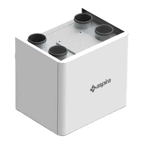
Aspira ASPIRVELO AIR ECOCOMFORT User manual

ASPIRVELO AIR ECOCOMFORT
UNITÀ DI VENTILAZIONE MONOSTANZA CON RECUPERO DI CALORE
MANUALE D’USO E DI INSTALLAZIONE PAG. 2
UNIDAD DE VENTILACION CONRECUPERACION DE CALOR
MANUAL DE USO E INSTALACIÓN PAG. 38
SINGLE ROOM HEAT RECOVERY UNIT
USER INSTRUCTIONS PAG. 11
PAG. 20
PAG. 29
UNITÉ DE VENTILATION MONO-PIÈCE AVEC RÉCUPÉRATION DE CHALEUR
MANUEL D'UTILISATION ET D'INSTALLATION
MONOSTANZA VENTILATOR MIT WÄRMERÜCKGEWINNUNG
BENUTZER- UND INSTALLATIONSHANDBUCH

2
ASPIRVELO
AIR ECOCOMFORT
ITALIANO
GRAZIE PER AVER ACQUISTATO IL NOSTRO PRODOTTO. PRIMA DI USARLO, LEGGERE IL MANUALE D’USO
ACCURATAMENTE E CONSERVARLO BENE PER CONSULTARLO IN FUTURO.
1. DESCRIZIONE DEL PRODOTTO
Unità di ventilazione e aspirazione decentralizzata con recupero di calore ad altissima efficienza. L’unità funziona
con il principio del recupero del calore rigenerativo: attraverso uno scambiatore di calore ceramico posto
all’interno del dispositivo che accumula il calore ceduto dal flusso d’aria entrante o uscente dalla stanza, e lo
restituisce quando il flusso inverte il proprio verso. L’unità ventilante è comandata da un motore DC Brushless
con funzionamento ad inversione di ciclo che permette il continuo scambio d’aria tra interno ed esterno. L’aria
viene costantemente filtrata attraverso un filtro G3 installato sul frontale dell’apparecchio e facilmente estraibile
al fine di consentirne la pulizia. L’unità è gestita da una elettronica di comando montata a parete che prevede tre
modalità di funzionamento: automatico, immissione ed estrazione aria. Inoltre l'elettronica di comando permette
di adeguare il funzionamento in base alla differenza fra la temperatura interna e la temperatura esterna. L'unità
di comando può gestire fino a 4 unità ventilanti in modalità combinata e regolare la velocità di estrazione o
immissione aria.
• Leggere attentamente le avvertenze contenute nel presente libretto, in quanto forniscono importanti indicazioni
riguardanti la sicurezza di installazione, d’uso e di manutenzione. Conservare con cura questo libretto per ogni
ulteriore consultazione.
• Dopo aver tolto l’imballaggio assicurarsi dell’integrità dell’apparecchio. In caso di dubbio non utilizzare
l’apparecchio e rivolgersi a personale professionalmente qualificato.
• Gli elementi dell’imballaggio (sacchetti in plastica, polistirolo espanso, chiodi, ecc.) non devono essere lasciati
alla portata dei bambini, in quanto potenziali fonti di pericolo.
• Prima di collegare l’apparecchio accertarsi che i dati di targa siano rispondenti a quelli della rete di distribuzione
elettrica (la targa è situata sul lato superiore del portamotore).
• Questo apparecchio dovrà essere destinato solo all’uso per il quale è stato espressamente concepito e cioè per
aerazione dei locali con recupero di calore.
• Ogni altro uso è da considerarsi improprio e quindi pericoloso. Il costruttore non può essere considerato
responsabile per eventuali danni derivanti da usi impropri, erronei ed irragionevoli.
• L’uso di un qualsiasi apparecchio elettrico comporta l’osservanza di alcune regole fondamentali. In particolare:
• Non toccare l’apparecchio con mani o piedi bagnati o umidi.
• Non usare l’apparecchio a piedi nudi.
• Non lasciare esposto l’apparecchio ad agenti atmosferici (pioggia, sole, ecc.).
• Non permettere che l’apparecchio sia usato da bambini o da incapaci senza sorveglianza.
• Prima di effettuare qualsiasi operazione di pulizia o di manutenzione, disinserire l’apparecchio dalla rete di
alimentazione elettrica, spegnendo l’interruttore dell’impianto.
• In caso di guasto e/o cattivo funzionamento dell’apparecchio, spegnerlo e non manometterlo.
3. AVVERTENZE GENERALI E ISTRUZIONI DI SICUREZZA
AVVERTENZA!
Leggere attentamente le istruzioni contenute in questo manuale, onde evitare il rischio di scosse
elettriche, incendi e lesioni personali.
2. DATI TECNICI
Tensione di alimentazione unità ventilante 12Vdc
Grado di protezione unità di comando IP20
Grado di protezione unità ventilante IPX4
Portata d'aria (25÷50) m³/h
Livello di pressione sonora 20dB @ 25 m³/h ; 25dB @ 50m³/h
Potenza max assorbita 2,0W @ 25 m³/h ; 2,8W @ 50 m³
3
ASPIRVELO
AIR ECOCOMFORT
ITALIANO
• Per l’eventuale riparazione rivolgersi al rivenditore e richiedere l’utilizzazione di ricambi originali.
• Il mancato rispetto di quanto sopra può compromettere la sicurezza dell’apparecchio.
• Allorché si decida di non utilizzare più un apparecchio di questo tipo si raccomanda di renderlo inoperante
scollegandolo dalla rete di alimentazione dopo aver staccato l’interruttore dell’impianto.
• Si raccomanda, inoltre, di rendere innocue quelle parti dell’apparecchio suscettibili di costituire un pericolo,
specialmente per i bambini che potrebbero servirsi dell’apparecchio fuori uso per i propri giochi.
• L’esecuzione dell’impianto elettrico deve essere conforme alle Norme per gli impianti elettrici negli edifici civili.
• Apparecchio conforme alle Direttive Europee: CE2006/95; CE2004/108.
• Essendo l’apparecchio costruito a regola d’arte, con un uso corretto ed una regolare manutenzione, durata ed
affidabilità elettrica e meccanica saranno più efficienti.
• Questo apparecchio non è da intendersi adatto all’uso da parte di persone (incluso bambini) con ridotte capacità
fisiche, sensoriali o mentali, o prive di esperienza e conoscenza, a meno che siano state supervisionate o istruite
riguardo all’uso dell’apparecchio da una persona responsabile della loro sicurezza. I bambini dovrebbero
essere supervisionati per assicurarsi che non giochino con l’apparecchio.
• L’installazione deve essere effettuata secondo le istruzioni del costruttore.
• Una errata installazione può causare danni a persone, animali o cose nei confronti dei quali il
costruttore non può essere considerato responsabile.
• L’apparecchio è costruito secondo le norme del doppio isolamento (Classe II) e quindi non necessita del cavo
di terra.
• Verificare che la portata elettrica dell’impianto e delle prese di corrente siano adeguate alla potenza massima
dell’apparecchio indicata in targa.
• In caso di dubbio rivolgersi ad una persona professionalmente qualificata.
• All’installazione occorre prevedere un interruttore onnipolare con distanza di apertura dei contatti uguale o
superiore a 3 mm.
• Non lasciare l’apparecchio inutilmente inserito. Spegnere l’interruttore generale dell’apparecchio quando lo
stesso non è utilizzato.
• Non ostruire la griglia di aspirazione.
• A norma delle vigenti Leggi antinfortunistiche assicurarsi che, ad installazione avvenuta dell’aspiratore, non
sia possibile, in nessun caso, accedere dal lato mandata alle parti in movimento. Se nel locale da ventilare è
installato un apparecchio a gas (o altri combustibili) è indispensabile verificare che vi sia un adeguato rientro
dell’aria, per garantire la perfetta combustione dello stesso ed il corretto funzionamento del ventilatore.
• Non installare l’aspiratore nello stesso condotto dove sono convogliati i fumi di un apparecchio a gas.
• L’installazione può essere eseguita solo a parete.
4. CONTENUTO DELLA CONFEZIONE
1. Unità ventilante
2. Scambiatore di calore con
maniglia di estrazione
3. Tubo telescopico
4. Unità di comando
5. Griglia dentro/fuori
6. Alimentatore 12Vcc
7. Foglio istruzioni
2
1
34
5
6

4
ASPIRVELO
AIR ECOCOMFORT
ITALIANO
6. INSTALLAZIONE - PREPARAZIONE DELLA PARETE
5. DIMENSIONI
180
180
47
max 280max 280
max 530 - min 240*
20
max Ø 160
* per spessori di parete inferiori a
280mm tagliare il tubo a seconda
della propria necessità ed utilizzare
una griglia esterna standard (non in
dotazione).
UNITÀ VENTILANTE CON RECUPERATORE
UNITÀ DI COMANDO ALIMENTATORE
140
85
77
40
82.5
150±10
150±10
90
15.5
19
31
T case
Realizzare, per tutto lo spessore della parete, un foro di diametro minimo 162 mm con inclinazione di 1° verso
l’ambiente esterno. Il foro deve essere posizionato ad una altezza minima di 2,3mt dal pavimento e a 100 mm da
eventuali pareti laterali (fig.1).
Utilizzando nello stesso ambiente due sistemi di ventilazione monostanza con recupero di calore serie Aspirvelo
Air Ecocomfort, nel caso di montaggio sulla stessa parete (fig. 2a), l’installazione deve essere effettuata in modo
tale che il centro dei fori di carotaggio siano ad una distanza minima di 1,2 metri.
Fig.1
STANZA
1°
min 100 mm
2,3 mt
Ø162
ESTERNO

5
ASPIRVELO
AIR ECOCOMFORT
ITALIANO
Fig.2b
Nel caso invece di montaggio su due pareti ad angolo, i centri dei fori di carotaggio devono trovarsi rispettivamente
ad 1,2 metri dalla parete opposta (fig. 2b).
7. INSTALLAZIONE DEL TUBO TELESCOPICO
1. Utilizzando l’apposita
maniglia, estrarre lo
scambiatore di calore come
indicato dalla fig.3.
Fig. 3
NON POSIZIONARE IL DISPOSITIVO SOPRA MOBILI
DELICATI O QUADRI. NON POSIZIONARE IL DISPOSITIVO
SOPRA O VICINO A TERMOSTATI AMBIENTE.
Fig.2a
1,2 mt
SCAMBIATORE DI CALORE
TUBO INTERNO
MANIGLIA
TUBO ESTERNO
1,2 mt
1,2 mt
2. Cospargere il foro appena realizzato
con malta cementizia.
3. Inserire il tubo telescopico
assicurandosi che il tubo di diametro
maggiore sia a filo con la parete
esterna (fig.4).
STANZA ESTERNO
TUBO
INTERNO TUBO
ESTERNO
TUBO ESTERNO
A FILO CON LA
PARETE
Fig. 4

6
ASPIRVELO
AIR ECOCOMFORT
ITALIANO
8. INSTALLAZIONE DEL TUBO TELESCOPICO, GRIGLIA E SCAMBIATORE DI CALORE
1. Attendere che la malta faccia presa.
2. Inserire la griglia “dentro fuori” comprimendo le molle sul tubo esterno (fig. 6)
3. Fissare la griglia
Fig. 6
TUBO ESTERNO
MOLLE
4. Inserire lo scambiatore di calore fino all’estremità del tubo interno. (fig. 7)
4. Far scorrere il tubo interno rispetto
al tubo esterno portandolo a filo con
la parete della stanza (fig. 5)
STANZA ESTERNO
TUBO
INTERNO TUBO
ESTERNO TUBO ESTERNO
A FILO CON LA PARETE
TUBO INTERNO
A FILO CON LA PARETE
DELLA STANZA
Fig. 5
SCAMBIATORE A FILO
CON IL TUBO INTERNO Fig. 7

7
ASPIRVELO
AIR ECOCOMFORT
ITALIANO
1. Sganciare il coperchio (2) dal portamotore premendo sui fori laterali (1) mediante un piccolo cacciavite (fig. 8).
2. Fratturare l’imposta prevista per il passaggio collegamenti (3), nel caso di collegamenti esterni non sotto
traccia fratturare le zone previste (4) sia sul portamotore che sul coperchio (fig. 9).
3. Fissare il portamotore in corrispondenza del foro di scarico mediante viti e tasselli (fig. 10).
4. Posizionare il cavo di alimentazione nell’apposita sede antitrazione (fig. 11).
Fig. 8
Fig. 10 Fig. 11
Fig. 9
9. INSTALLAZIONE DELL'UNITÀ VENTILANTE
3
4
4
4
1
1
2

8
ASPIRVELO
AIR ECOCOMFORT
ITALIANO
10. COLLEGAMENTI ELETTRICI
1. Svitando l’apposita vite di fissaggio, smontare il coperchio dell’unità di comando. Collegare i cavi di uscita
dell’alimentatore (DC OUT) all’unità di comando rispettando le polarità (fig.12).
L’Aspirvelo Air Ecocomfort può funzionare con due unità ventilanti fino ad un massimo di quattro. Il sistema è stato
pensato per funzionare in maniera alternata. Se per esempio in un ambiente sono installate due unità, il primo
dispositivo opera immettendo aria dall’esterno mentre il secondo dispositivo opera estraendo aria dalla stanza.
Quando dopo un certo tempo si ha l’inversione del senso di rotazione delle ventole, il primo dispositivo estrae l’aria
verso l’esterno mentre il secondo dispositivo immette l’aria nella stanza. L’alternanza del funzionamento in coppia,
assicura che la somma della portata d’aria immessa sia pari alla somma della portata estratta.
ESEMPIO DI COLLEGAMENTO CON 4 MOTORI:
La coppia di motori A-B è in contro fase con la coppia
C-D (fig. 13a)
ESEMPIO DI COLLEGAMENTO CON 2 MOTORI:
Il motore A ed il motore C sono in contro fase (fig.13b)
Fig. 12
2. Collegare l’unità di comando alla morsettiera dell’aspiratore/i.
VITE DI FISSAGGIO
12Vdc
+ -
Fig. 13a Fig. 13b

9
ASPIRVELO
AIR ECOCOMFORT
ITALIANO
3. Collegare l’alimentatore 12Vdc alla rete elettrica per mezzo di un interruttore che consenta di spegnere
l’apparecchio quando non è utilizzato.
4. Applicare a scatto il coperchio sul portamotore dell’unità ventilante.
5. Applicare il coperchio sull’unità di comando.
L’unità di comando, montata sia a parete che su scatola 503, è costituita da due deviatori a slitta e da una manopola di
regolazione. Il deviatore a slitta di sinistra, permette di modificare la portata scambiata fra la stanza e l’esterno da un
valore massimo di 50 m³/h ad un valore minimo di 25 m³/h. Inoltre posizionando il deviatore a slitta di sinistra sulla
posizione OFF, si ottiene lo spegnimento del sistema.
Il deviatore a slitta di destra, prevede tre modalità di funzionamento:
• Auto: alterna il flusso fra estrazione ed immissione aria;
• In: solo immissione aria;
• Out: solo estrazione aria.
La manopola di regolazione consente di variare la durata del ciclo di immissione/estrazione aria, da un minimo di 35
secondi ad un massimo di 200 secondi in funzione della differenza di temperatura ΔT fra l’esterno e l’interno.
Se la differenza di temperatura ΔT fra la stanza e l’esterno è elevata, per garantire il rendimento termico, il tempo
ciclo deve essere il minore possibile (35 secondi). Se invece la differenza di temperatura ΔT è prossima a zero, il ciclo
deve durare il più possibile (200 secondi).
Se per esempio in inverno la temperatura esterna è –15°C e quindi la differenza di temperatura ΔT fra interno ed
esterno è elevata, ruotare la manopola fino alla posizione (1). Contrariamente in una giornata primaverile, dove la
differenza di temperatura ΔT è minima o prossima allo zero, ruotare la manopola in posizione (2) (fig.14).
11. FUNZIONAMENTO DELL’UNITÀ DI COMANDO
1
2
Q=50m³/h
Q=25m³/h
Fig. 14

10
ASPIRVELO
AIR ECOCOMFORT
ITALIANO
1. Sostituzione del filtro: dopo aver interrotto il circuito di alimentazione, smontare il coperchio e svitare le
quattro viti come indicato in fig. 15. Pulire periodicamente il filtro immergendolo in acqua fredda.
12. PULIZIA E MANUTENZIONE
13. ACCESSORI E PARTI DI RICAMBIO
2. PULIZIA PLASTICHE: Dopo aver interrotto il circuito di alimentazione, usando la massima attenzione, pulire
con acqua e detersivo neutro le parti che lo richiedono.
Unità ventilante con recuperatore e griglia Cod. AP19979
Filtro G3 di ricambio Cod. AP19978
Terminale esterno di immissione aria TPE-150N nero Cod. AP19900
Terminale esterno di immissione aria TPE-150B bianco Cod. AP19901
Terminale esterno di immissione aria TPE-150G grigio Cod. AP19902
ATTENZIONE:
NON IMMERGERE IN ACQUA O ALTRI LIQUIDI LE PARTI ELETTRICHE.
14. SMALTIMENTO
Il simbolo del cassonetto barrato riportato sull’apparecchiatura indica che il prodotto alla fine della propria vita utile deve
essere raccolto separatamente dagli altri rifiuti.
L’utente dovrà, pertanto, conferire l’apparecchiatura giunta a fine vita agli idonei centri di raccolta differenziata dei rifiuti
elettronici ed elettrotecnici, oppure riconsegnarla al rivenditore al momento dell’acquisto di una nuova apparecchiatura
di tipo equivalente, in ragione di uno a uno. L’adeguata raccolta differenziata per l’avvio successivo dell’apparecchiatura
dismessa al riciclaggio, al trattamento e allo smaltimento ambientalmente compatibile contribuisce ad evitare possibili
effetti negativi sull’ambiente e sulla salute e favorisce il riciclo dei materiali di cui è composta l’apparecchiatura. Lo
smaltimento abusivo del prodotto da parte dell’utente comporta l’applicazione delle sanzioni amministrative di cui al D.Lgs.
n. 22/1997” (articolo 50 e seguenti del D.Lgs. n. 22/1997).
ATTENZIONE:
Informazione importante per lo smaltimento ecosostenibile dell’apparecchio.
Fig. 15

11
ENGLISH
ASPIRVELO
AIR ECOCOMFORT
THANK YOU FOR PURCHASING OUR PRODUCT. BEFORE USE, READ THE USER MANUAL CAREFULLY AND KEEP IT
SAFE FOR CONSULTATION IN THE FUTURE.
1. PRODUCT DESCRIPTION
Decentralized ventilation and suction unit with high efficiency heat recovery. The unit works with the principle of
regenerative heat recovery: by means of a ceramic heat exchanger placed inside the device that collects the heat
given off by the air flow entering or leaving the room, and returns it when the flow reverses its direction. The fan
unit is controlled by a DC Brushless motor with reverse cycle operation that allows the continuous exchange of air
between inside and outside. The air is continually filtered through a G3 filter installed on the front of the appliance
and easily removable for cleaning purposes. The unit is managed by a wall mounted electronic control unit that
features three operation modes: automatic, collection and extraction of air. Furthermore, the electronic control
allows for the adjustment of operation according to the difference between interior and exterior temperature. The
control unit can manage up to 4 ventilation units in combined mode and regulate the speed of air extraction or
collection.
2. TECHNICAL DATA
Fan unit power supply 12Vdc
Control unit degree of protection IP20
Fan unit degree of protection IPX4
Airflow (25 ÷ 50) m³ / h
Sound pressure level 20dB @ 25 m³ / h ; 25dB @ 50m³ / h
Maximum power 2,0W @ 25 m³ / h ; 2,8W @ 50 m³
• Read carefully the instructions in this booklet as they give important information on the correct installation, use
and maintenance of the appliance.
• Keep this booklet in a safe place so that it will be available for future reference.
• After unpacking check the integrity of the set. In case of doubt do not use the set and ask for qualified person’s
intervention.
• All the packaging (plastic bags, polystyrene foam, nails, etc) must be kept out of the reach of children.
• Before connecting the appliance to the mains supply ensure that the rating label specifications correspond to
your electrical supply. (The rating label is to be found on the top part of the motor holder).
• This appliance must only be used for the purpose for which it was designed i.e. ventilation of rooms.
• All other uses must be considered to be potentially dangerous. The Manufacturer cannot be held responsible
for any damage caused by improper, incorrect or unreasonable use.
• The safe use of any electrical appliance involves the observing of certain basic rules, in particular:
• Do not touch the appliance with wet or moist hands or feet.
• Do not use the appliance with bare feet.
• Do not pull the plug from the power socket by the mains lead of the appliance itself.
• Do not leave the appliance where it is exposed to adverse elements such as rain, salt etc.
• Do not let young children, aged or infirm people use the device without supervision.
• Before beginning any cleaning or maintenance operations disconnect the appliance from the electrical
supply by taking out the plug or switching off the appliance insolation switch.
• In case of a fault and/or malfunction of the appliance, switch it off but do not attempt to rectify.
• Seek advice from a suitably qualified person.
3. SAFETY INSTRUCTIONS
WARNING!
READ THIS INSTRUCTION CAREFULLY IN ORDER TO AVOID THE RISK OF ELECTRIC SHOCK, FIRE OR
INJURY.

12
ENGLISH
ASPIRVELO
AIR ECOCOMFORT
• If repair is necessary contact the Manufacturer and ask for only original spare parts.
• If the above action is not carried out, the safety of the appliance could be jeopardized.
• Should it be decided not to use this appliance any longer, it should be removed from the electrical supply and
rendered inoperative, then disposed of in the normal manner. It is also recommended to make harmless those
parts of the appliance which could be harmful, especially to children who might play with the disused appliance.
• The installation must conform to the requirements of the latest issue of the I.E.E. wiring regulations.
• This appliance has been constructed to comply with the requirements of the following European Directives
CE2006/95; CE2004/108.
• The set is workmanlike manufactured. A correct use and a regular maintenance guarantee life and reliability
of all electrical and mechanical parts.
• This appliance is not intended for use by persons (including children) with reduced physical, sensory or lack
of experience and knowledge unless they have been given supervision or instruction concerning use of the
appliance by a person responsible for their safety. Children should bensure that they do not play with the
appliance.
• Installation must be carried out as detailed in these instructions. The user is warned that incorrect
installation could cause harm to persons or animals or damage to property. The Manufacturer cannot be
held responsible in such cases.
• The apparatus is double insulated (Class II) and does not require earthing.
• Check that the current carrying capacity of the mains wiring and socket are adequate for the maximum rating
of the device shown on the rating label. In case of doubt consult a suitably qualified person.
• When installing, it is necessary to use a double pole switch with a contact separation of 3 mm or more.
• Do not leave the appliance plugged if unnecessary. Switch off the main switch of the appliance when the
appliance is not in use.
• Do not obstruct the air inlet or outlet grilles.
• In conformity with prevention and safety laws in force, when installation of exhaust fan is completed, make sure
that it is not at all possible to reach the motion parts from the inlet side. On the contrary it is necessary to mount
the special protection shutter (cod. AP0885, AP0893).
• If there is already a combustion fuel appliance in the room, it is essential to ensure that the air supply to the
room is adequate for the correct functionning of both the combustion appliance and the fan.
• Do not install the fan in the same duct where gas appliance fume is conveyed.
• The appliance must discharge into a single exhaust pipe or directly outside the building.
• The system can be either wall-mounted or ceiling-mounted.
4. PACKAGE CONTENTS
1. Fan unit
2. Heat exchanger with extraction
handle
3. Telescopic tube
4. Control unit
5. Grid inside/outside
6. Power supply 12Vcc
7. Instruction sheet
2
1
34
5
6

13
ENGLISH
ASPIRVELO
AIR ECOCOMFORT
77
40
82.5
150±10
150±10
90
15.5
19
31
Tcase
5. MEASUREMENTS
180
180
47
max 280max 280
max 530 - min 240*
20
max Ø 160
* For wall thickness of less than
280mm, cut the pipe according to
necessity and use a standard outdoor
grill (not supplied).
FAN UNIT WITH HEAT RECOVERY
CONTROL UNIT POWER SUPPLY
140
85
6. INSTALLATION - WALL PREPARATION
Make a hole, through the whole thickness of the wall, of a minimum diameter of 162 mm, with an inclination of 1°
towards the exterior. The hole should be located at a minimum height of 2.3m from the ground and 100 mm from
the wall side (Figure 1).
Using two monostanza ventilation systems with Aspirvelo Air Ecocomfort heat recovery series in the same
environment, when mounted on the same wall (figure 2a), the installation must be carried out in such a way that
the centers of the drill holes are at a minimum distance of 1.2 meters.
Figure 1
ROOM
1°
min 100mm
2.3m
Ø162
EXTERNAL

14
ENGLISH
ASPIRVELO
AIR ECOCOMFORT
Figure 2b
If instead mounted on two corner walls, the centers of the drill holes must be respectively located at 1.2 meters
from the opposite wall (fig. 2b).
7. INSTALLATION OF THE TELESCOPIC TUBE
1. Using the handle, pull out the
heat exchanger as shown in
Figure 3.
Figure 3
DO NOT PLACE THE DEVICE ON DELICATE FURNITURE
OR PAINTINGS. DO NOT PLACE THE DEVICE ON OR
NEAR THERMOSTATS.
Figure 2a
1.2m
HEAT EXCHANGER
INTERNAL TUBE
HANDLE
EXTERNAL TUBE
1.2m
1.2m
2. Dust the newly drilled hole with cement
mortar.
3. Insert the telescopic tube making sure
that the larger diameter tube is flush
with the outer wall (Figure 4).
ROOM EXTERNAL
TUBE
INTERNAL TUBE
EXTERNAL
EXTERNAL TUBE
FLUSH WITH
THE WALL
Figure 4

15
ENGLISH
ASPIRVELO
AIR ECOCOMFORT
ROOM EXTERNAL
TUBE
INTERNAL TUBE
EXTERNAL EXTERNAL TUBE
FLUSH WITH THE WALL
INTERNAL TUBE
FLUSH WITH THE WALL
OF THE ROOM
Figure 5
4. Slide the inner tube
with respect to the
outer tube until it is
flush with the wall of
the room (Figure 5)
8. INSTALLATION OF THE TELESCOPIC TUBE, GRILL AND HEAT EXCHANGER
1. Wait until the mortar sets.
2. Place the rack "inside out" compressing the springs on the external tube (Figure 6)
3. Secure the grill
Figure 6
EXTERNAL TUBE
SPRINGS
4. Place the heat exchanger at the extremity of the inner tube. (Figure 7)
WIRE EXCHANGER
WITH INTERNAL TUBE Figure 7

16
ENGLISH
ASPIRVELO
AIR ECOCOMFORT
1. Unhook the cover (2) from the motor support by pressing on the side holes (1) using a small screwdriver
(Figure 8).
2. Fracture the shutter provided for the transfer of connections (3), in the case of non-concealed external
connections, fracture the zones provided for (4) both on the motor support and on the cover (Figure 9).
3. Fix the motor support at the evacuation hole with screws and raw plugs (Figure 10).
4. Place the power cable in the appropriate place (Figure 11).
Figure 8
Figure 10 Figure 11
Figure 9
9. INSTALLATION OF FAN UNIT
3
4
4
4
1
1
2

17
ENGLISH
ASPIRVELO
AIR ECOCOMFORT
10. ELECTRICAL CONNECTIONS
1. Unscrewing the fastening screws, remove the cover of the control unit. Connect the power supply output (DC
OUT) to the control unit respecting the polarity (Figure 12).
The Aspirvelo Air Ecocomfort can work with two ventilation units up to a maximum of four. The system is designed to
operate in an alternating way. If for example two units are installed, the first device operates by introducing air from
the outside, while the second device operates by extracting air from the room. When after some time there is the
inversion of the direction of rotation of the fans, the first device extracts the air to the outside while the second device
brings the air into the room. The alternation of operation in torque, ensures that the sum of the air flow emitted is
equal to the sum of the air flow extracted.
EXAMPLE OF CONNECTION WITH 4 MOTORS:
The pair of motors A-B is in counter phase with the
C-D pair (Fig. 13a)
EXAMPLE OF CONNECTION WITH 2 MOTORS:
Motors A and C are in counter phase (Figure 13b)
Figure 12
2. Connect the control unit to the terminal of the vacuum/s.
FIXING SCREWS
12Vdc
+ -
Figure 13a Figure 13b

18
ENGLISH
ASPIRVELO
AIR ECOCOMFORT
3. Connect the 12Vdc power supply to the mains by means of a switch which allows the device to be switched off
when not in use.
4. Snap closed the cover on the fan motor support unit.
5. Place the cover on the control unit.
The control unit, mounted either on a wall or box 503, is made up of two sliding switches and one control knob. The
sliding switch on the left, allows for the modification of the flow between the room and the outside from a maximum
of 50 m³ / h to a minimum of 25 m³ / h. Besides placing the sliding switch on the left in the OFF position, you get a
system shutdown.
The sliding switch on the right provides for three modes of operation:
• Auto: changes the flow from extraction to collection of air;
• In: air collection only;
• Out: air extraction only.
The adjustment knob allows for the variation of the duration of cycles of air collection/extraction, from a minimum
of 35 seconds to a maximum of 200 seconds depending on the temperature ΔT difference between the exterior and
the interior.
If the difference in temperature ΔT between the room and the exterior is raised, in order to guarantee the thermal
output, the time cycle must be the shortest possible (35 seconds). If instead the difference in temperature ΔT is close
to zero, the cycle must last as long as possible (200 seconds).
If for example in winter the exterior temperature is -15°C and thus the difference in temperature ΔT between the
interior and the exterior is raised, turn the knob to position (1). Unlike a day in spring, where the difference in
temperature ΔT is minimal or close to zero, turn the knob to position (2) (Figure 14).
11. OPERATION OF THE CONTROL UNIT
1
2
Q=50m³/h
Q=25m³/h
Figure 14

19
ENGLISH
ASPIRVELO
AIR ECOCOMFORT
1. Changing the filter: after interrupting the power supply circuit, remove the cover and unscrew the four screws
as shown in Figure 15. Clean the filter periodically by immersing it in cold water.
12. CLEANING AND MAINTENANCE
13. ACCESSORIES AND SPARE PARTS
2. CLEANING PLASTICS: After interrupting the power supply circuit with the utmost care, clean the parts that
require it with water and neutral detergent.
Fan unit with heat recovery and grill Code AP19979
Exchange filter G3 Code AP19978
External air collection terminal TPE-150N black Cod. AP19900
External air collection terminal TPE-150B white Code AP19901
External air collection terminal TPE-150G grey Code AP19902
WARNING:
DO NOT IMMERSE THE ELECTRICAL PARTS IN WATER OR OTHER LIQUID.
Figure 15
14. DISPOSAL
WARNING
WARNING
:
Important information concerning the environment friendly disposal of the appliance
This product conforms to EU Directive 2002/96/EC. The symbol of the barred waste bin indicates that, at the end of its useful
life, the product has to be collected separately from the domestic waste.
The user will have to take the product to a collection centre for waste electrical and electronic equipment, or return it to a
retailer on purchase of a replacement. Failure to do so may incur the penalties established by laws governing waste disposal.
Proper differential collection and the subsequent recycling, processing and environmentally compatible disposal of waste
equipments avoids unnecessary damage to the environment and possible related health risk and promotes also recycling of
the materials used in the appliance.

FRANÇAISE
20
ASPIRVELO
AIR ECOCOMFORT
MERCI D'AVOIR ACHETÉ NOTRE PRODUIT. AVANT TOUTE UTILISATION, VEUILLEZ LIRE ATTENTIVEMENT CE
MANUEL, ET CONSERVEZ-LE POUR POUVOIR VOUS Y RÉFÉRER ULTÉRIEUREMENT.
1. DESCRIPTION DU PRODUIT
Unité de ventilation et d'aspiration décentralisée avec récupération de chaleur à très haute efficacité. L'unité
fonctionne selon un principe de récupération de chaleur régénérative : à travers un échangeur de chaleur en
céramique situé à l'intérieur du dispositif qui accumule la chaleur du flux d'air entrant ou sortant de la pièce, et
le restitue quand le flux s'inverse. L'unité de ventilation est contrôlée par un moteur à courant continu Brushless
avec fonctionnement à inversion de cycle qui permet un échange d'air continu entre l'intérieur et l'extérieur. L'air
est constamment filtré à travers un filtre G3 installé sur la face avant de l'appareil et facilement extractible afin
de pouvoir le nettoyer. L'unité est gérée par un circuit électronique de commande monté sur le mur, qui offre trois
modes de fonctionnement : automatique, entrée et sortie d'air. De plus le système électronique de commande
permet de régler le fonctionnement en fonction de la température interne et de la température externe. L'unité
de commande peut gérer le fonctionnement de 4 unités de ventilation différentes en mode combiné et de régler
la vitesse de sortie ou d'entrée d'air.
2. DONNÉES TECHNIQUES
Tension d'alimentation unité de ventilation 12 V cc
Classe de protection de l'unité de commande IP20
Classe de protection de l'unité de ventilation IPX4
Débit d'air (25÷50) m³/h
Niveau de pression sonore 20 dB @ 25 m³/h ; 25dB @ 50m³/h
Puissance max absorbée 2,0 W @ 25 m³/h ; 2,8 W @ 50 m³
• Lire attentivement les instructions contenues dans ce livret, car elles fournissent d’importantes indications sur
la sécurité pour l’installation, I’utilisation et la maintenance. Conserver soigneusement ce livret afin de pouvoir le
consulter ultérieurement en cas de besoin.
• Aprés avoir enlevé l’emballage, s’assurer que l’appareil soit intact. En cas de doutes, ne pas se servir de l’appareil
et s’adresser au personnel qualifié. Les éléments de l’emballage (sachets en plastique, polystyrène expansé, clous,
etc.. ) ne doivent pas être laissés à la portée des enfants car peuvent représenter des sources potentielles de danger.
• Avant de relier l’appareil, s’assurer que le s données indiquées sur la plaquette correspondent à celles du réseau de
distribution electrique. (La plaquette est située sur la partie supérieure du porte-moteur).
• Cet appareil ne doit être destiné qu’à l’usage pour lequel il a été expressément conçu, c’est-à-dire pour l’aération
des locaux. Tout autre usage doit être considéré impropre et par consequent dangereux. Le constructeur ne peut
pas être tenu pour responsable en cas d’éventuels dommages causés par une utilisation impropre, erronée et
irraisonnée.
• L’utilisation d’un appareil électrique quelconque implique l’observation de certaines règles fondamentales. En
particulier:
• Ne pas toucher l’appareil avec les mains ou les pieds mouillés ou humides.
• Ne pas utiliser l’appareil avec les pieds nus.
• Ne pas exposer l’appareil aux agents atmosphériques (pluie, soleil, etc...).
• Ne pas laisser sans surveillance les enfants ou les personnes incapables d’utiliser l’appareil tout seuls.
• Avantd’effectuertoute opérationde nettoyage oudemaintenance, déconnecterl’appareil duréseau d’alimentation
électrique et éteindre l’interrupteur de l’installation.
• En cas de panne et/ou de mauvais fonctionnement de l’appareil, éteindre celui-ci et ne le toucher plus.
3. INSTRUCTIONS GENERALES
ATTENTION:
LISEZ ATTENTIVEMENT LES INSTRUCTIONS DE CE MANUEL POUR ÉVITER LES RISQUES DE CHOC
ÉLECTRIQUE, UN INCENDIE OU DES BLESSURES.
Table of contents
Languages:
Other Aspira Fan manuals

Aspira
Aspira ECOCOMFORT 2.0 SMART Series Technical specifications

Aspira
Aspira AFM User manual

Aspira
Aspira VOLO 120/48'' RL User manual

Aspira
Aspira ASPIRSIMPLEX User manual

Aspira
Aspira ASPIRVELO Series User manual

Aspira
Aspira ASPIRCOMFORT PRO X 380V User manual

Aspira
Aspira FRESKO User manual

Aspira
Aspira AC100 Series User manual

Aspira
Aspira ASPIRCOMFORT V User manual

Aspira
Aspira ASPIRCOMFORT PRO dH User manual