Assa Abloy effeff TSB-Controller II User manual

Experience a safer
and more open world
assaabloyopeningsolutions.de
D0126601
User manual
TSB-Controller II
Escape route technology

2EN
EN
Firmware version 4.0.1220
FT Managerversion 4.0.1220
Open Source Licenses ASSA ABLOY Sicherheitstechnik GmbH has the source code of
the software used in the scope of Open Source licenses
(such as FreeRTOS™, newlib, lwIP) available on request:
http://www.assaabloy.com/com/global/opensourcelicense/
Publisher
ASSA ABLOY Sicherheitstechnik GmbH
Bildstockstrasse 20
72458 Albstadt
Germany
Phone: +49 (0) 7431 / 123-0
Telefax: +49 (0) 7431 / 123 240
Email: albstadt@assaabloy.com
Internet: www.assaabloyopeningsolutions.de
Document number and date
D0126601 02.2021
Copyright
© 2021, ASSA ABLOY Sicherheitstechnik GmbH
This document and all its parts are copyrighted. Any use or changes outside the
strict limits of the copyright are prohibited and liable to prosecution unless prior
consent has been obtained from ASSAABLOYSicherheitstechnikGmbH .
This particularly applies to any copying, translations, microforms, or storing and
processing in electronic systems.
Read this manual thoroughly before use and keep it in a safe place for later
reference. The manual contains important information about the product,
particularly for the intended use, safety, installation, use, maintenance and
disposal.
Hand the manual over to the user after installation and pass the manual on to
the purchaser together with the product if the product is sold.

3
EN
Notes . . . . . . . . . . . . . . . . . . . . . . . . . . . . . . . . . . . . . . . . . . . . . . . . . . 4
About this manual . . . . . . . . . . . . . . . . . . . . . . . . . . . . . . . . . . . . . . . . . . . . . . . . . . . . . . . . . . . . 4
Meaning of the symbols . . . . . . . . . . . . . . . . . . . . . . . . . . . . . . . . . . . . . . . . . . . . . . . . . . . . . . 4
Safety instructions. . . . . . . . . . . . . . . . . . . . . . . . . . . . . . . . . . . . . . . . . . . . . . . . . . . . . . . . . . . . 5
Intended use . . . . . . . . . . . . . . . . . . . . . . . . . . . . . . . . . . . . . . . . . . . . . . . . . . . . . . . . . . . . . . . . . 6
Operation . . . . . . . . . . . . . . . . . . . . . . . . . . . . . . . . . . . . . . . . . . . . . . 7
General description. . . . . . . . . . . . . . . . . . . . . . . . . . . . . . . . . . . . . . . . . . . . . . . . . . . . . . . . . . . 7
Usage and range of functions . . . . . . . . . . . . . . . . . . . . . . . . . . . . . . . . . . . . . . . . . . . . . . . . . 7
Control and monitoring . . . . . . . . . . . . . . . . . . . . . . . . . . . . . . . . . . . . . . . . . . . . . . . . . . . . . . 8
Installation . . . . . . . . . . . . . . . . . . . . . . . . . . . . . . . . . . . . . . . . . . . . . 9
Lines and wiring . . . . . . . . . . . . . . . . . . . . . . . . . . . . . . . . . . . . . . . . . . . . . . . . . . . . . . . . . . . . . 10
Bus controller installation. . . . . . . . . . . . . . . . . . . . . . . . . . . . . . . . . . . . . . . . . . . . . . . . . . . . 11
Power supply . . . . . . . . . . . . . . . . . . . . . . . . . . . . . . . . . . . . . . . . . . . . . . . . . . . . . . . . . . . . . . . . 11
Connections. . . . . . . . . . . . . . . . . . . . . . . . . . . . . . . . . . . . . . . . . . . . . . . . . . . . . . . . . . . . . . . . . 12
Resetting to factory settings . . . . . . . . . . . . . . . . . . . . . . . . . . . . . . . . . . . . . . . . . . . . . . . . . 14
Replacing the battery. . . . . . . . . . . . . . . . . . . . . . . . . . . . . . . . . . . . . . . . . . . . . . . . . . . . . . . . 14
LED signalling. . . . . . . . . . . . . . . . . . . . . . . . . . . . . . . . . . . . . . . . . . . . . . . . . . . . . . . . . . . . . . . . 15
Set-up operation. . . . . . . . . . . . . . . . . . . . . . . . . . . . . . . . . . . . . . .16
Check list. . . . . . . . . . . . . . . . . . . . . . . . . . . . . . . . . . . . . . . . . . . . . . . . . . . . . . . . . . . . . . . . . . . . 16
Turning on the system . . . . . . . . . . . . . . . . . . . . . . . . . . . . . . . . . . . . . . . . . . . . . . . . . . . . . . . 16
Network connection. . . . . . . . . . . . . . . . . . . . . . . . . . . . . . . . . . . . . . . . . . . . . . . . . . . . . . . . . 17
FT Manager . . . . . . . . . . . . . . . . . . . . . . . . . . . . . . . . . . . . . . . . . . . . . . . . . . . . . . . . . . . . . . . . . . 18
System settings. . . . . . . . . . . . . . . . . . . . . . . . . . . . . . . . . . . . . . . . . . . . . . . . . . . . . . . . . . . . . . 18
Connection to server PC . . . . . . . . . . . . . . . . . . . . . . . . . . . . . . . . . . . . . . . . . . . . . . . . . . . . . 20
Technical data . . . . . . . . . . . . . . . . . . . . . . . . . . . . . . . . . . . . . . . . .22
Certification . . . . . . . . . . . . . . . . . . . . . . . . . . . . . . . . . . . . . . . . . . . . . . . . . . . . . . . . . . . . . . . . . 22
Warranty, disposal . . . . . . . . . . . . . . . . . . . . . . . . . . . . . . . . . . . . .23
Warranty . . . . . . . . . . . . . . . . . . . . . . . . . . . . . . . . . . . . . . . . . . . . . . . . . . . . . . . . . . . . . . . . . . . . 23
Updated information . . . . . . . . . . . . . . . . . . . . . . . . . . . . . . . . . . . . . . . . . . . . . . . . . . . . . . . . 23
Disposal . . . . . . . . . . . . . . . . . . . . . . . . . . . . . . . . . . . . . . . . . . . . . . . . . . . . . . . . . . . . . . . . . . . . . 23
Table of contents
4EN Notes
About this manual
This manual was written for electricians and appropriately trained personnel. The
manual was designed to enable you to install and operate the device safely and
make full use of the permitted range of applications the control terminal has to
offer.
Meaning of the symbols
Danger!
Safety notice: Failure to observe these warnings will lead to death or serious
injury.
Warning!
Safety notice: Failure to observe these warnings may lead to death or serious
injury.
Caution!
Safety notice: Failure to observe these warnings may lead to injury.
Important!
Note: Failure to observe these warnings can lead to property damage and impair
the function of the product.
Note!
Note:Additional information on operating the product.
D
!
!
A
I
Notes

5
EN
Notes
Safety instructions
Warning!
Danger arising from modification of the product: The safety features of this
product are an essential requirement for its conformity with EltVTR. No changes
which are not described in this manual may be undertaken.
Danger due to faulty commissioning: In order to ensure the safety of the
product, commissioning must be performed by a qualified person. ASSA ABLOY
Sicherheitstechnik GmbH offers training for qualification in the requisite skills.
Any work on electrical connections may only be carried out on the TSB Controller
and control devices when they are in a de-energised state to eliminate any risk
of physical injury or damage to the equipment. Observe VDE regulations in this
respect.
Danger due to faulty maintenance: The owner is responsible for correct instal-
lation and functional inspection of the product and connected components. The
safe function must be tested by a trained qualified expert at least once per year.
Requirements established by inspection authorities must be complied with. ASSA
ABLOY Sicherheitstechnik GmbH offers training for qualification in the requisite
skills.
Caution!
Risk of injury due to damage: The device must not be used if it is damaged.
Damaged cables and connector assemblies also represent a safety hazard and
must not be used.
!
!

6EN Notes
Intended use
The TSB Controller II serves as a link between a PC and the TS bus. Data transfer
between the PC and TSB Controller II takes place via Ethernet. Data transmission
between the TSB Controller II and the individual escape door control units or
control terminals (peripherals) takes place via the TS bus.
The TSB Controller II must be mounted on top-hat rails in accordance with DIN EN
60715 TH35. The wiring takes place via screw-type terminals.
The TSB Controller II is suitable for installation and use in accordance with this
manual. It is not intended for any other type of use.
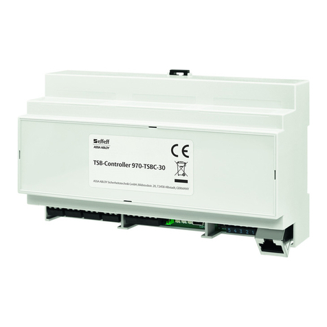
Fig. 1:
TSB Controller II

7
EN
Operation
General description
Bus technology is primarily used in modern control technology in equipment
where a larger number of individual devices are monitored and controlled.
The TS bus uses two-wire technology to ensure that installation between the
individual devices and a central control point is restricted to a two-wire bus line.
Up to 110 peripherals can be controlled and monitored on the PC via the
two-wired bus line.
Usage and range of functions
· Use in systems with up to 110 peripherals.
· Minimum installation work when using effeff TS bus.
· Interface for OPC and visual display of building layout.
·FT Manager web interface
· Configuration and parametrisation for systems and devices
· Events logging
· Maintenance module
As a central interface, the FT Manager web interface offers the system integrator
the option of integrating configuration and administration functions by linking
them into its user interface. No special software must be installed and maintained
on the computer except a standard web browser (Internet Explorer 7 and above,
Mozilla Firefox 3 and above). A service PC is directly connected using a crossover
cable (included in the supply package). The system can also be integrated into the
building network. A patch cable must be used to connect to a building network
(not included in the supply package). System security is assured thanks to
password protection, a backup function and encrypted transmission to the PC.
TS bus (door
control bus)
110 peripherals
Operation

8EN Operation
Note!
Functionality in the event of PC failure: If the PC should crash, the TS bus will
continue to function. The doors can be controlled using an optional control panel
instead. If the TS bus fails, the safety functions in escape door control units or
escape door control terminals and connected components, such as escape door
strikes and emergency open switches, remain operative for safety reasons.
Control and monitoring
Peripherals and escape doors are controlled and monitored from the PC,
preferably using the effeff escape route visual display 970-VIS. System status
messages and statistics are configured and displayed on the integrated web
application FT manager.
I
970-VIS and
FT Manager

9
EN
Installation
Warning!
Danger due to faulty Installation: The bus controller module and connected
devices may only be installed and set up for operation by a qualified electrician.
Danger due to non-compliance with the applicable regulations: You must ob-
serve and comply with the German Electrical Engineering Association (VDE) and
local electricity company regulations when installing equipment.
You must also comply with safety regulations regarding work on electrical sys-
tems..
Important!
Components at risk of electrostatic discharge: Electronic components in
equipment should not be touched to ensure that electrostatic discharge does not
cause injury or damage. If you cannot avoid touching electronic components, you
should use a suitable anti-static tool.
To ensure that the risk of electrostatic discharge is kept to a minimum, the person
who is working on the system should ensure that they are not carrying an electric
charge. They should take suitable measures such as wearing an anti-static wrist
strap.
!
A
Installation

10 EN Installation
Lines and wiring
You must comply with a few installation requirements to ensure that the system
functions correctly. Please follow the instructions below and carry out installation
and connection work carefully.
TS bus installation
Important!
Disturbances due to excessive total line length and line resistances: The total
length of the bus line should be no longer than 1,000 m and resistance in the line
to peripherals should be no greater than 65 ohm. This ensures that no problems
arise due to high interconnect capacitances and resistances. We recommend
using bus repeater 901-35 for projects where longer line lengths are required.
· You must install a separate, shielded line which is used exclusively to connect
peripherals to the bus. We recommend using telecommunications cable type
J-Y(St)Y with a cross-section of 0.28 mm² or 0.5 mm².
· Do not use free wires in the bus line for additional control tasks or power supply
to external peripherals, since this may interfere with data transmission.
· Install only one wire for the data line and one wire for ground in the bus con-
nection for the whole system. Never connect two or more wires in parallel to
increase the cross-section size, as this can cause malfunctions.
Connecting peripherals to the TS bus
Important!
Damage due to short circuit: The bus line is poled. If the bus line is connected
incorrectly, it will short-circuit and block the whole bus system, possibly damag-
ing connected devices permanently.
Each peripheral features two connecting terminals for the TS bus, to which the
bus line is connected:
·TS bus data terminal: for connecting the data cable
·TS bus GND terminal: for the system ground
Connect TS bus
A
A

11
EN
Installation
Bus controller installation
The TSB Controller II is intended for installation in a suitable electrical distributor.
It is mounted on top-hat rails according to DIN EN 60715 TH35. The wiring takes
place via screw-type terminals.
The installation location of the TSB Controller II distributor must meet the follow-
ing conditions:
· It must be on the inside of the building.
· It must not be exposed to any unusual environmental conditions, such as ag-
gressive vapours or high humidity.
· The TSB Controller II should be easily accessible in a protected area and not be
exposed to direct sunlight.
· When mounting the TSB Controller IIon the wall, take care not to damage any
wiring or pipes inside the wall itself. The module rack for the TSB Controller II and
fastening screws must not come into contact with conductive elements in the
building’s structure.
Power supply
The TSB Controller II must be powered by an external power supply.
The power supply unit must comply with the specifications described in chapter
“Technical data”, page22.
Installation
location
external power
supply

12 EN Installation
Connections
Fig. 2:
Terminal strip
BMA
4 3 2 1
+24 V
GN D
nc c no
6 5
9
1
12 11 10 9 8 7
15 14 13
18 17 16
21 20 19
24 23 22
nc c no nc c no nc c no
2
–
+
11 12 14
13
ON
346
75
10
8
Functional earthing
Connection
Fire alarm
No fire alarm
Local connection Central connection
Jumper 8 inserted Jumper 8 not inserted
10 9 8 7
Connection of a fire alarm system
4 3
BMA
+
–
12 11
GND
+ 24 V DC
Input 1:
10 9 8 7
Input 2:
4 3
BMA
+
–
12 11
GND
+24 V DC ± 15%
Input 3:
Connection
Inputs
10 9 8 7

13
EN
Installation
Pos. No. Description Pos. No. Description
1 1
2
3
4
reserved
reserved
supply + 24V
supply 0V
2 5
6
TSB ground
TSB data
3 7
8
9
10
11
12
Input 1
Input 2
Ground
Input 3
Fire alarm system +
Fire alarm system -
4 13
14
15
Relay 1 no
Relay 1 c
Relay 1 nc
5 16
17
18
Relay 2 no
Relay 2 c
Relay 2 nc
6 19
20
21
Relay 3 no
Relay 3 c
Relay 3 nc
7 22
23
24
Relay 4 no
Relay 4 c
Relay 4 nc
8 Jumper (plug connector)
for deactivating a fire
alarm system
Jumper set: Fire alarm
system off
9 LED signalling: (page 15)
LED red
LED yellow
LED green
10 DIP switch 1 – Reserved
for expansions at a later
date
11 DIP switch 2 –
For factory reset
12 Port–Reserved for
expansions at a later date
13 Functional earthing FE 14 Ethernet
Tab. 1:
Key for Fig. 2

14 EN Installation
Resetting to factory settings
Resetting to factory settings will lose all changes to the operating data.
Reset to factory settings
The factory settings are reset from the basic state or from a fault.
1 Set DIP switch 2 to OFF if necessary (Fig. 2– 11 ).
DIP switch 2 is now in the OFF position.
2 Set DIP switch 2 from OFF to ON.
Red LED, yellow LED and green LED flash (1 : 1).
3 Wait at least 10 seconds.
Red LED continues to flash (1 : 1), yellow LED and green LED are off.
4 Set DIP switch 2 from ON to OFF again.
Red LED, yellow LED and green LED are on.
Factory settings are applied.
This resets the IP address.
After a pause of 3 seconds, a restart takes place automatically.
The TSB Controller II is back in its basic state.
5 Perform a commissioning (“Set-up operation”, page16).
Replacing the battery
In the event of a power failure, the battery buffers the RTC (real-time clock). If the
battery needs to be replaced, contact support (“Warranty, disposal”, page23).

15
EN
Installation
LED signalling
The LEDs are used for status indication. Start, basic state (normal operation), data
traffic, faults and the reset to factory settings are indicated and documented by
the behaviour of the LEDs.
LED red LED yellow LED green
After switching on/booting
On On On Booting procedure after switching on
Booting takes about 20 seconds.
Only then will the controller take control of the LEDs.
Off On On Reference run (bus scan)
Normal operation
Off Off On Basic state – no data traffic
Off Flashes 5: 1 Data traffic via TS bus
Off Flashes 5: 1 Data traffic via network bus
Off Flashes 5: 1 Flashes 5: 1 Data traffic via network bus and TS bus
Faults
On Malfunction
On Off Off No device on the bus (only during
restart)
On Flashes 1: 1 Off Device on bus is missing
On Off Flashes 1: 1 New device on the bus (only during restart)
Tab. 2:
LED signals

16 EN Set-up operation
Check list
Check installation
· Is the power supply to the peripherals secured?
· Are all peripherals, escape door strikes and contacts connected?
· Is the bus line connected to the peripherals?
· Is the power supply connected to the controller?
· Is the bus line connected to the controller?
Check the settings on the 970 TSB Controller and peripherals
· Have the system settings been configured?
· Are all peripherals set to Bus operation?
· Has each peripheral been assigned a peripheral address?
Turning on the system
Initial operation of peripheral devices
1 Switch on the power supply to each individual peripheral.
2 Check each individual peripheral at its installation location to verify that it is
fully functional.
3 There must be no alarm active on peripherals once they are checked. If an
alarm is active, it must first be switched off and the cause of the alarm
eliminated before continuing.
Initial operation of the 970 TSB Controller
1 Turn on the power supply.
After switching on, the operating status is signalled via the LEDs (“LED
signalling”, page15).
2 Switch on your PC and make the required settings in FT Manager.
Inspecting
Commissioning
Set-up operation

17
EN
Set-up operation
Network connection
You need to establish a network connection between the TSB Controller and your
PC, so that you can access the web interface in the FT Manager .
This can be done in several ways:
· Direct network connection using a cross-over cable (included in supply package)
· Initial/set-up operation using service PC
· A patch cable to connect to a building network (not included in the supply package).
· Coordination with the network administrator required
· Configuration for use in the network.
Escape route technology network structure
Fig. 3:
Network structure
TS Bus
Repeater
901-35
Service
PC
FT-Manager
Configuration of escape route technology
using a web browser on TSB Controller web
interface
Server
PC
FT-Server
Interface to WINMAG
Monitor and control
OPC server option
Monitor and control
WebFT
For visual display and
controling over Microsoft
Internet Explorer
WINMAG
Alarm management
as OPC client
Visual display using:
Server PC monitor
Client PC with MSIE
Ethernet
1
2
3
4
5
TSB-Controller
970-TSBC-20

18 EN Set-up operation
FT Manager
Connection to service PC
The network connection between the TSB Controller and a service PC is estab-
lished using a cross-over cable.
The escape route technology is configured under Windows®10 using FT Manager
and a web browser.
System settings
The system settings on the controller, such as TCP/IP address assignment, are
made via the FT Manager’s web interface.
Configuring the network connection
You need to check the LAN settings on the network card and adjust if necessary to
ensure that the TSB Controller can communicate with your PC.
The bus controller’s DHCP server is active ex works.
1 Open the Windows settings window (Fig. 4 – 1 ).
2 Click Network and Internet (– 2 ).
The Settings window opens.
3 Click Change adaptation options (– 3 ).
4 Double-click on Ethernet (– 4 ).
5 Click on Properties (– 5 ). Depending on the configuration of your PC, you
may need to confirm your authorization with a password.
6 Select Internet Protocol version 4 (TCP/IPv4) (– 6 ) and confirm with OK.
7 Select the options Obtain IP address automatically and
Obtain DNS server address automatically (– 7 ) and confirm with OK.
The network connection is configured.
FT Manager
System
settings

19
EN
Set-up operation
Fig. 4:
Configuring the
network
connection
1
4
3
2
1
5
7
7
6

20 EN Set-up operation
Opening the FT Manager
Once configuration is complete, you can then open up the FT Manager in a web
browser.
1 Start your web browser.
2 Enter the following URL in the address bar:
https://1.1.1.1 and confirm the entry.
A security notice will appear.
Note!
Unknown security certificate warning message: The security certification
encrypts communication between the computer and the 970-TSBC. This security
certification is trustworthy, but the web browser won’t recognise it
3 You will therefore need to select Continue to load this website ... (Fig. 5 – 1 ).
The FT Manager will now open in the browser window (Fig. 6).
Connection to server PC
If the TSB Controller is to be used in a network, you will need to coordinate with
the network administrator.
Configuration for use in a network
You can permanently assign IP addresses in a network or obtain them
automatically.
The TSB Controller requires a permanent address. The required settings should be
configured in FT Manager.
Web browser
I
Use in the
network
This manual suits for next models
1
Table of contents
Other Assa Abloy Controllers manuals

Assa Abloy
Assa Abloy CLIQ CLM User manual

Assa Abloy
Assa Abloy InControl 3270 User manual

Assa Abloy
Assa Abloy Sargent 52-4424 User manual

Assa Abloy
Assa Abloy effeff 970-TSBC-30-10 User manual

Assa Abloy
Assa Abloy Incedo EAC-M90 User manual

Assa Abloy
Assa Abloy Sargent P106 User manual

Assa Abloy
Assa Abloy Sargent 700 User manual

Assa Abloy
Assa Abloy Sargent IN100 Guide

Assa Abloy
Assa Abloy LCU9016III User manual