Assa Abloy Incedo EAC-M90 User manual

1
Incedo™
EAC-M90
Installation Guide

www.assaabloyopeningsolutions.com
3
1 Introduction
Product Description
Incedo™ Cloud is ASSA ABLOY’s access control
system, optimised for small to medium sized
businesses that require an agile access solution
to keep the business moving.
This powerful access control solution has features
which punch well above its weight. An Incedo
system is easy to install, configure and manage,
thanks to its design and use of plug-and-play
hardware with simple in-field configuration.
The addition of the EAC-M90 updater controller
offers many enterprise security features without
the associated costs. The Incedo EAC-M90 has
been designed to provide not only a high level
of security for your building by utilising Seos®
technology and OSDP Signo®readers, but also
to manage ASSA ABLOY PULSE energy-harvesting
keys, cylinders, Aperio offline locks and
credentials.
2 What’s in the packaging?
EAC-M90 Contents
Incedo Cloud, hosted within ASSA ABLOY’s
ultra-secure environment offers the owner and an
administrator access to the system 24/7. No longer
must you be on-site to amend configuration or
access vital information to run reports. Simply
connect to Incedo from a PC with internet access
to take real-time control of your Incedo system.
The interface is easy to use, with auto ID of
hardware, simple configuration menus, and
multiple means of adding credentials to the
system with the software being automatically
updated as new releases become available.
Reliable and backed by a strong warranty,
ASSA ABLOY puts access control from a trusted
industry leader within reach.
Version 1.0 Version 1.0
Drill Guide
Quick Start Guide
+VIN
-VIN
TAMPER
0V COM
PSU MON
BAT LOW
CNTCT I1
COM
EXIT I2
I3
COM
I4
NC
COM
NO
+
0V
RELAY1
NC
COM
NO
RELAY2
NC
COM
NO
PORT1
NC
COM
NO
RELAY4
AUX 1AUX 2
+
0V
CNTCT I1
COM
EXIT I2
I3
COM
I4
RELAY3
+
B
A
-
PORT2
+
B
A
-
CAN
+
HI
LO
-
ON
6.3A, 250V AC
5mm x 20mm
Drill Guide
Quick Start Guide
+VIN
-VIN
TAMPER
0V COM
PSU MON
BAT LOW
CNTCT I1
COM
EXIT I2
I3
COM
I4
NC
COM
NO
+
0V
RELAY1
NC
COM
NO
RELAY2
NC
COM
NO
PORT1
NC
COM
NO
RELAY4
AUX 1AUX 2
+
0V
CNTCT I1
COM
EXIT I2
I3
COM
I4
RELAY3
+
B
A
-
PORT2
+
B
A
-
CAN
+
HI
LO
-
ON
6.3A, 250V AC
5mm x 20mm

www.assaabloyopeningsolutions.com
5
4 System Architecture
TCP/IP
TCP/IP
EAC-M90 master
controller
Customers’
network
Fused Spur
Please refer to reader
manufacturers wiring
specification
The EAC-M90 will only
accommodate up to
2 wired doors in total
in a combination of 2
doors with readers and
exit requests or 2 doors
read in/read out
Version 1.0
3 Installation preparation
System requirements
∙ Compatible PC Browser
∙ Connection to a network with
access to the Internet
∙ Mains power with 6A fused spur
Suggested Tools
∙ Electric drill
∙ Drill bits (masonry/steel to suit the site
wall materials)
∙ Screwdriver, small, flat
∙ Wire strippers
∙ Side cutters
∙ Site plan (to lay out door and reader locations)
Additional Hardware
∙ ASSA ABLOY signo readers
∙ Electric strike locks and/or magnetic locks
∙ Push buttons for Request-to-Exit (REX)
∙ Door Position Sensor (DPS)
∙ Mains power cable
∙ Cable for Door Position Sensor and Request-
to-Exit
5 Mounting the EAC-M90
Mounting Location Considerations
Shelter and Security
Secure Indoor location Away from weather
Single EAC-M90 cable run considerations
Customers’
network
Choose a mounting location
to reduce door cablings runs
Fused spur
Version 1.0
Drill Guide
Quick Start Guide
+VIN
-VIN
TAMPER
0VCOM
PSUMON
BATLOW
CNTCTI1
COM
EXITI2
I3
COM
I4
NC
COM
NO
+
0V
RELAY1
NC
COM
NO
RELAY2
NC
COM
NO
PORT1
NC
COM
NO
RELAY4
AUX1AUX 2
+
0V
CNTCTI1
COM
EXITI2
I3
COM
I4
RELAY3
+
B
A
-
PORT2
+
B
A
-
CAN
+
HI
LO
-
ON
6.3A, 250V AC
5mm x 20mm
DPS DPS
RTE
Entry reader Entry reader
Exit reader

www.assaabloyopeningsolutions.com
7
Removal/Fitting the Lid
Mark up the mounting holes using the drilling template
1. Select fasteners that are appropriate for the
mounting surface (masonry/wood/drywall)
2. Select the drill size appropriate for the fasteners
3. Fix the Drilling Template against the chosen
vertical surface making sure that the top edge
is horizontal. (Remember to allow 30 mm
clearance on the left of the EAC-M90 enclosure
to allow the door to hinge fully open)
4. Centre punch the two mounting hole locations
5. Drill holes of a diameter that is suitable
for the fasteners
6. Remove the cover from the enclosure
(as per instructions above)
7. Mount the enclosure to the surface
8. Replace the cover after the system wiring is
complete, making sure to re-attach the earth
strap to the cover
Version 1.0 Version 1.0
2/8
Drill Guide
8 mm 38 mm
DRAFT 08
3/8
YUASA
NP7-12 (BT00578)
12V, 7Ah
+VIN
-VIN
TAMPER
0V COM
PSU MON
BAT L OW
CNTCT I1
COM
EXIT I2
I3
COM
I4
NC
COM
NO
+
0V
RELAY 1
NC
COM
NO
RELAY 2
NC
COM
NO
PORT1
NC
COM
NO
RELAY 4
AUX 1 AUX 2
+
0V
CNTCT I1
COM
EXIT I2
I3
COM
I4
RELAY 3
+
B
A
-
PORT2
+
B
A
-
CAN
+
HI
LO
-
ON
DRAFT 08
8/8
We reserve the right to make technical modifications. Version Incedo Metal Box QSG Version 2. 10 2022 ENG
TM
+VIN
-VIN
TAMPER
0VCOM
PSUMON
BAT LOW
CNTCTI1
COM
EXITI2
I3
COM
I4
NC
COM
NO
+
0V
RELAY1
NC
COM
NO
RELAY2
NC
COM
NO
PORT1
NC
COM
NO
RELAY4
AUX1 AUX 2
+
0V
CNTCTI1
COM
EXITI2
I3
COM
I4
RELAY3
+
B
A
-
PORT2
+
B
A
-
CAN
+
HI
LO
-
ON
EAC-M90
}
DRAFT 08
Fitting of PCB to board
PCB is supplied as a
separate component
to M90 enclosure
and must be fitted
after mounting the
M90 enclosure to the
wall using the screws
provided.
(battery not supplied with product)

www.assaabloyopeningsolutions.com
9
6 Wiring the System
EAC-M90 updater controller cable specifications
Metal Oxide Variators (MOV’s) included
in the packaging
Where to use the supplied MOV’s
The MOV’s must be connected across the cable
supply for the Locking device, at the device, not at the
controller, to prevent sparking at the relay contacts.
The Supplied MOV’s are only for 12V applications
and are MANDATORY.
NO
COM
+12V
∙Application ∙Conductors
∙(#of Wires)
∙Cross
∙Sectional Area ∙AWG ∙Max Cable
Length
Door Locking
Device (12V
and higher)
20.75 mm218 150m*
Card Reader 4 0.33 mm222 1200m
Door
Contact 20.52 mm220 150m
Request-
to-Exit 20.52 mm220 150m
∙MOV Rating 25V RMS 500A 77V Max Clamping*
0V
*Depends upon
voltage of door lock
*Replacement MOV’s
are available on
Amazon or other
good retailers
Version 1.0 Version 1.0
NC
2 doors read in/read out
6/8
+V
0V
MOV
CAT5
Incedo
Metal Boxed
Controller
EAC-M90
Made in South Africa NR PCS 1
DC
200-240V AC
12V, 7Ah
3.15A N
L1
L
N
E
PSU
+V
0V
MOV
B
A
-
+
B
A
-
+
A
B
+
-
A
B
+
-
OSDP OSDP
12
12
11
22
+VIN
-VIN
TAMPER
0V COM
PSU MON
BAT L OW
CNTCT I1
COM
EXIT I2
I3
COM
I4
NC
COM
NO
+
0V
RELAY 1
NC
COM
NO
RELAY 2
NC
COM
NO
PORT1
NC
COM
NO
RELAY 4
AUX 1 AUX 2
+
0V
CNTCT I1
COM
EXIT I2
I3
COM
I4
RELAY 3
+
B
A
-
PORT2
+
B
A
-
CAN
+
HI
LO
-
ON
EOL TERM
ON OFF
DRAFT 08
EAC-M90 key component diagramThe EAC-M90 will
accommodate either
2 wired doors in a
combination of 2 doors
with readers and exit
requests or 2 doors
read in/read out
2 doors with readers and exit requests
5/8
+V
0V
MOV
CAT5
Incedo
Metal Boxed
Controller
EAC-M90
Made in South Africa NR PCS 1
DC
200-240V AC
12V, 7Ah
3.15A N
L1
L
N
E
PSU
+V
0V
MOV
B
A
-
+
A
B
+
-
OSDP OSDP
12
11
22
+VIN
-VIN
TAMPER
0V COM
PSU MON
BAT L OW
CNTCT I1
COM
EXIT I2
I3
COM
I4
NC
COM
NO
+
0V
RELAY 1
NC
COM
NO
RELAY 2
NC
COM
NO
PORT1
NC
COM
NO
RELAY 4
AUX 1 AUX 2
+
0V
CNTCT I1
COM
EXIT I2
I3
COM
I4
RELAY 3
+
B
A
-
PORT2
+
B
A
-
CAN
+
HI
LO
-
ON
EOL TERM
ON OFF
DRAFT 08

www.assaabloyopeningsolutions.com
11
Some strike locks and maglocks have built-in arc
suppression. Consult the installation information
for the locks you are using. It is recommended
that the MOV’s (supplied with the EAC-M90) are
connected across any inductive local to the load.
NB: The supplied MOV’s are only suitable for 12V
applications.
Terminal blocks easily
unplug giving simple
access to the terminal
screw heads.
Caution: Inadequate
spark suppression can
result in early failure of
relay contacts – and will
void the warranty on
the affected EAC-M90
updater controller
Version 1.0 Version 1.0
PCB handling
The Controller and Reader Modules are sensitive
to Electrostatic Discharges (ESD). Observe
precautions while handling the circuit board
assemblies by using proper grounding straps and
handling precautions at all times.
Mains supply Connection
Mains Cable Specification
∙ Connect the power cable to a non-switched
6.3 A fused spur which is local to the panel
and clearly identified
∙ Select a cable that is in accordance to National
Wiring code best practices of your local authority
Version 1.0
Mains Cable Connection
1. Connect your mains cable between the fuse
spur and the EAC-M90 updater controller
(if unsure seek assistance from a qualified
electrician)
2. Pass the mains cable through the access holes
provided and follow the route indicated by the
yellow arrow. (It should pass behind the battery,
if it were installed)
3. Strip the ends mains cable, exposing 10 mm
of the conductors
4. Press down on the terminal buttons while
threading each stripped wire end into its
corresponding terminal block (highlighted
in the below diagram by the yellow arrow)
5. Releasing the terminal button will clamp the
stripped wire end in place
6. Turn on the mains supply
7. The LCD panel will illuminate and show the IP
address once a network connection has been
established
8. It is now safe to connect the recommended
12V battery (not included) using the EAC-M90’s
integrated spade terminal plugs
Tamper
Circuit Switch
Battery Cables
Lid Earth
Cable Plug
Mains Cable Route
Power Supply
Mains Terminal Block
www.assaabloyopeningsolutions.com
13
Version 1.0 Version 1.0
LCD display panel menu flow
Within the EAC-M90 unit, there is a panel showing the connection, network,
status and system details.
Update
No Updates Found
Updating (USB)
Verifying
Cancel/
Exit
Navigate
UP
Navigate
DOWN Select/
Enter
Mac: 00177A2C0026
IP: 192.168.100.1
00177A2C0026
No Connection
CONNECTION
Menu Network Network
Incedo Status
Connected
(0)
Disconnected
(19)
Cancel/
Exit
Navigate
UP
Navigate
DOWN Select/
Enter
CUSTOMERS’ NETWORK
Menu Status
Cancel/
Exit
Navigate
UP
Navigate
DOWN Select/
Enter
STATUS
Menu System System Update Update
Checking Updates
Update
USB
Start Update
< No Yes >
Updating (USB)
Flashing
Cancel/
Exit
Navigate
UP
Navigate
DOWN Select/
Enter
SYSTEM DETAILS
To navigate through the menu there are 4 keys left, up, down and right,
see below each of them including:

www.assaabloyopeningsolutions.com
15
Version 1.0
∙Contact Rating ∙Configuration
“[3A, 30V DC]
[3A, 125V AC]”
Single Pole Double Throw
(Break-Before-Make)
∙Contacts ∙Operations
NO, NC, COM 100000
∙Auxiliary Power Ports (2x) ∙Specification
Connector 2-Way Screw Plug
Supply voltage 10-13.8V DC
Overcurrent limit threshold 2.1A (per port)
∙Readers Ports (2x) ∙Specification
Connector 4-Way Screw Plug
Supply voltage 10 -12V DC
Overcurrent limit threshold 0.7A (per port)
∙Power supply ∙Specification
Supply voltage 200-240V AC (50/60Hz)
Power consumption 0.8A
Output current (max.) 5A (incl. battery charging current)
Battery charging current 1A
“Output voltage
(buffer operation)” 11-13. 8V DC
“Output voltage
(battery-assisted operation)” 10-13.8V DC
∙Battery ∙Specification
Type Lead Acid
Voltage 12V
Capacity 7Ah
Physical Dimensions 65 mm x 101 mm x 151 mm
∙Battery Protection Fuse ∙Specification
Length 20 mm, 0.787"
Type Slow-blow
Rating 6.3A
Location Under power supply cover
∙Connector ∙Purpose
Rj45 Ethernet, 10/100 Base T,
half or full duplex
Note:
∙ Only connect the
battery after all
system wiring is
complete and
tested on the
built-in power supply
7 Electrical Specifications

www.assaabloyopeningsolutions.com
17
8 Copyright and Trademarks
Copyright
© 2023 ASSA ABLOY Corporation/ASSA ABLOY AB.
All rights reserved.
This document may not be reproduced,
disseminated or republished in any form without the
prior written permission of ASSA ABLOY Corporation
Trademarks
ASSA ABLOY, Incedo and SEOS are trademarks or
registered trademarks of ASSA ABLOY, ASSA ABLOY
AB, or its affiliate(s) in the US and other countries
and may not be used without permission. All other
trademarks, service marks, and product or service
names are trademarks or registered trademarks of
their respective owners.
Packaging disposal information:
Box – PAP 20 – Paper
Bag – PET 1 – Plastic
Leaflet – PAP 22 – Paper
Bubblewrap – LDPE 4 – Plastic
Please check your country regulations
for waste management.
Version 1.0 Version 1.0
9 Notes

www.assaabloyopeningsolutions.com
19
Version 1.0 Version 1.0

The ASSA ABLOY Group is the global leader
in access solutions. Every day, we help billions
of people experience a more open world.
ASSA ABLOY Opening Solutions leads
the development within door openings
and products for access solutions in
homes, businesses and institutions. Our offering
includes doors, door and window hardware, locks,
access control and service.
© Images: All rights reserved by ASSA ABLOY. We reserve the right to make technical modifications. Version: 3140168_AA_IncedoTM_installationguide_07_2023_ENG
ASSA ABLOY Opening Solutions Middle East
UAE Office
P.O. Box 37765
Jabel Ali, Industrial Area 1
Dubai, United Arab Emirates
Tel: +971 4 880 4888
Fax: +971 4 880 4888
Qatar Office
P.O. Box 32522
D-Ring Road, Al Mataar
Al Qadeem District, Regus Business Centre
Fax: +971 4 880 4888
1st Floor, Office 109
Jabel Ali, Industrial Area 1
Doha, Qatar
Tel: +974 4 442 31264/65/66
Saudi Arabia Office
P.O. Box 25960
Abdulaziz Main Road,
2nd Floor, Riyadh, Kingdom of
Saudi Arabia
Tel: +966 1141 62075
Egypt Office
P.O. Box 11341
4A, Shafik Ghorbal
St. Roxy Cairo, Egypt
Tel: +20 1223475737
Fax: +20 2225 7481
www.assaabloy.com
Table of contents
Other Assa Abloy Controllers manuals

Assa Abloy
Assa Abloy effeff 970-TSBC-30-10 User manual

Assa Abloy
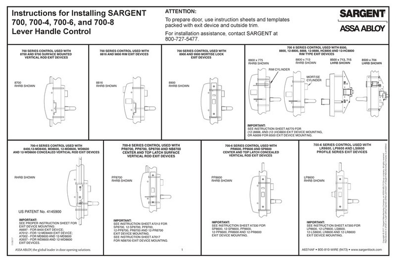
Assa Abloy Sargent 700 User manual

Assa Abloy
Assa Abloy effeff TSB-Controller II User manual

Assa Abloy
Assa Abloy CLIQ CLM User manual

Assa Abloy
Assa Abloy Sargent 52-4424 User manual

Assa Abloy
Assa Abloy Sargent IN100 Guide

Assa Abloy
Assa Abloy Sargent P106 User manual

Assa Abloy
Assa Abloy LCU9016III User manual

Assa Abloy
Assa Abloy InControl 3270 User manual