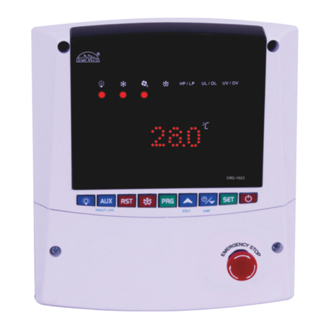
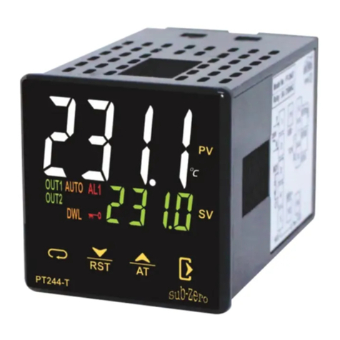
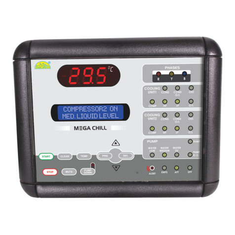
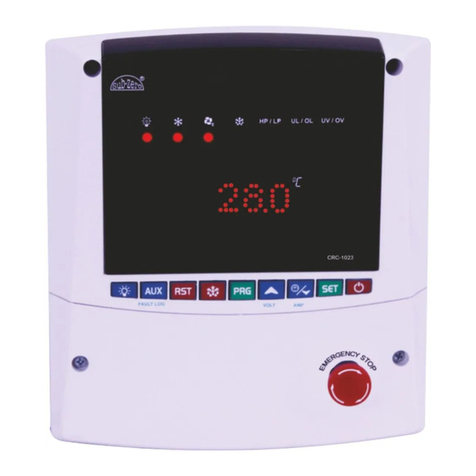
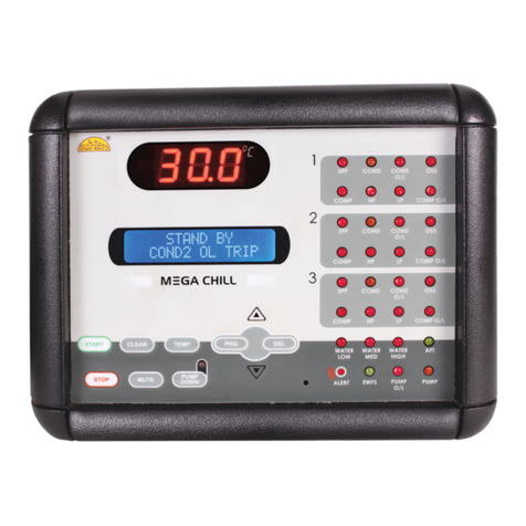
Sub-Zero Mega Chill User manual

COMPRESSOR2 ON
MED. LIQUID LEVEL
0
29.5C
R
R
A. S. C
ONTROLS
PVT. LTD.
Navi Mumbai, India 91-22-27782005 91-22-27782002Tel: Fax: email: [email protected] www.ascontrols.comweb:

CONTENTS
1. Accessaries in Box 3
2. Introduction
2.1 Main Features 4
2.2 Hardware Description 4
3. Hardware 5
3.1 Mega Chill User Interface 5
3.2 Input/Output Board 7
3.3 Sensors 8
3.4 Prokey 8
3.5 Transformer 8
3.6 Dimensions 9
3.7 Connections 10
4. Operations 12
4.1 Description - Inputs / Outputs 12
4.2 Mega Chill Keypad 13
4.3 How to Turn On/Off the Chiller 15
4.4 Water Pump 16
4.5 Water Temperature 16
4.6 Set-Point and Differential 16
4.7 Antifreeze 16
4.8 PUMP-DOWN 17
4.9 Water Level 17
5. Programming 18
5.1 Programming Levels 18
5.2 USER Parameters 18
5.3 FACTORY Parameters 19
5.4 Parameter Description & Values 21
6. Alarms 25
7. Technical Specifications 26
8. Precautions & Care 27
1
2 COMPRESSOR2 COMPRESSOR

NO.
1.
2.
3.
4.
QTY
1No.
1No.
4Nos.
1No.
ITEMS
TOROIDAL TRANSFORMER WITH SCREW
(I/P: 0-230V, O/P1: 0-9V @0.35A, O/P2: 0-10V @0.5A)
CATALOG
PROKEY
SCREWS (4X12)
5. 2Nos.
NTC SENSORS (1.5m)
6. 1No.
COMMUNICATION CORD(2m)
LIQUID LEVEL SENSORS (2m)
OR
LIQUID LEVEL SWITCH
23
1.AccessariesinBox
ItemsIncluded
Specifications are subject to change due to continuous improvements of
our products. No consequential damage or field labour is included in the
sales of products mentioned in this manual. The manufacturer is not
liableforincorrectuse/misuseoftheproductmentioned.
A.S. Controls Pvt Ltd. All rights reserved Sub-Zero and the Sub-Zero logo are
registeredtrademarksofA.S.ControlsPvtLtd.
NO.
1.
QTY
3Nos.
ITEMS
OptionalItems
NTC SENSORS (1.5m)
2. 4Nos.
2 COMPRESSOR2 COMPRESSOR

54
2. INTRODUCTION
The “MEGA CHILL-2COMP” is a
two compressor chiller controller .
This integrates all the required
functionsofthechiller.
It is very user friendly due to the
LCD provided which gives all the
parameters, messages, alarms
etc on the display. In addition to
the LCD there are LED's provided
for instant status on all controls in
thesystem.
2.1 MainFeatures
The Mega Chill controller allows
you to manage refrigeration units
havingdifferentconfigurations.
WATERcondensation.
AIRcondensation.
System’sFunctions:
Thesystemcontrolsandregulates
thefollowingconditions:
Water temperature
according to the user’s
location of the sensor.
Protection of the
compressor with indication
of any possible fault.
Display of Chiller status on
temperature on
LCD and
LED display.
Regulates level of water via
a water solenoid valve.
2.2HardwareDescription
Thebasicsystemcomprisesof
MegaChillUserinterface
Input/Outputboard
Mega chill is the intelligent part
of the system. It also represents
the ‘user interface’ for an easy
communication between user and
thecontroller.
3.1 MegaChillUserInterface
Mega Chill User Interface is a user friendly board which integrates all
controllerkeys,displayLCDanddisplayLEDs.
3. Hardware
COMPRESSOR2 ON
MED. LIQUID LEVEL
2 COMPRESSOR2 COMPRESSOR
29.5
COMPRESSOR2 ON
MED. LIQUID LEVEL
29.5

67
LiquidCrystalDisplay(LCD)
TheLCDscreenshowsdescription
of the controller parameters, and
any other information concerning
thecontrolledvariables.
Display2rowsX16characters.
CharacterSize5.56X2.96mm.
Liquid Crystal Display (LCD)
LightEmittingDiodes(LED)
There are 23 LED indications on
thechillerfrontpanelindicating:
Phases-all3phasesare
displayedasRYB.
Faults - Red blinking LED
ALERT Indicates that there is a
fault.
Individual device fault - Red
LED indicates that there is a
faultinthatparticulardevice.
Device OK status - Green LED
indicatesthatthedeviceisOK.
Deviceisinactive-Blank LED
indicatesthatthedeviceis
inactive.
COMPRESSOR 2 ON
MED. LIQUID LEVEL
Light Emitting Diodes (LED)
3.2 Input/OutputBoard
The Relay board represents the
core of the system, where the
signals coming from the probes,
digitalinputsetc.areprocessed.
Onthisboardyoucanlocate:
1. Terminalsforpowersource-
10Vac(yellow)&9Vac(red).
2. Liquid level sensor inputs
(LevelSensors).
3. Analoginputs(sensors).
4. DigitalInputs(alarms).
5. Digitaloutputs(relay).
6. Telephone connector for user
interfaceconnection.
Input/ Output
2 COMPRESSOR2 COMPRESSOR

89
3.3 Sensors
Japanese NTC thermistors, housed in a water proof I.P. 68 metal
casing.
(Custom made sensors are available in various sizes and material)
3.4 Prokey
This hardware key enables the manufacturer to enter programming
Level2(FactoryLevelProgramming).
Prokey
(Only for equipment manufacturer)
3.5 Transformer
System uses a highly reliable Toroidal transformer as it’s power supply
source.
Transformer
Standard Sensor ½”BSP Sensor SS 316L Sensor
3.6 Dimensions
Input/OutputBoard
MegaChillUserInterface
Panelcutout124mmX167mm (Alldimensionsinmm)
167
45
124
160
205
178
163
119
134
2 COMPRESSOR2 COMPRESSOR
243mm
130mm
150mm
75mm
50mm
10mm
10mm
85mm
50mm
223mm
To Display

10 11
3.7 Connections
8wayLANcable
Chiller Interface Terminal for panel mounting
Input/OutputBoard
2 COMPRESSOR2 COMPRESSOR
ALL FUSE = 1.5Amp
FUSE
FUSE
C
NO
FUSE
NC
PUMP
COND.1
COMP.2
COND.2
C
NO
COMP.1
C
NO
C
NO
C
NO
C
NO
FUSE
FUSE
WATER SV
FUSE
To Display
AC1
AC2
TRANSFORMER
~ ~
9V
10V
PUMP
DOWN SV2
PUMP
DOWN SV1
FUSE
FUSE
ALARM
C
NO
C
NO
C
NO
FUSE
HIGH
MED
LOW
LIQ
LEVEL
SENSOR
ANTI FREEZE
WATER IN
COND OUT
COND IN
CONTROL
WATER OUT
TRIP SIGNAL
B PHASE
Y PHASE
R PHASE
HP1
LP1
COMP1 O/L
OSS1
HP2
LP2
COMP2 O/L
OSS2
COND1 O/L
COND2 O/L
EWFS
SPP
NEUTRAL
PUMP O/L
SENSOR
COMPRESSOR2 ON
MED. LIQUID LEVEL
29.5
LIQ
LEVEL
SWITCH
OR
MED
LOW
REF.

12 13
4.1 Description- Input /Outputs
Analog Inputs (Probe)
The system has the following
analog (probe) inputs.
1. CONTROL - Used as the
main controlling probe based
on which the set point will
regulate the system.
2. COND IN - Indicates
Condenser Inlet temperature.
3. COND OUT - Indicates
Condenser Outlet
temperature.
4. WATER IN - Senses Water
(Chiller) Inlet temperature.
5. WATER OUT - Senses Water
(Chiller) Outlet temperature.
6. ANTI FREEZE : Used as an
Internal Anti Freeze control.
Digital Outputs (Relay)
System will operate the following
devices
1. Chiller Pump
2. Compressor1
3. Condenser Fan1
4. Liquid SV1 for Pump Down1
5. Compressor2
6. Condenser Fan2
7. Liquid SV2 for Pump Down2
8. Water SV
9. Alarm
Mega chill manages the following
protections
Digital Inputs (Trip Signals)
1. HP1 - High Pressure for Comp1
2. LP1 - Low Pressure for Comp1
3. Compressor Overload1
4. OSS1 - Oil Safety Switch1
5. COND. Fan O/L1 -
Condenser Fan Overload1
6. HP2 - High Pressure for Comp2
7. LP2 - Low Pressure for Comp2
8. Compressor Overload2
9. OSS2 - Oil Safety Switch for
Comp2
10.COND. Fan O/L2 -
Condenser Fan Overload2
11.EWFS (water cooled)-
Evaporator Water Flow
Switch.
12.Pump Overload
13.Single Phase Preventor
14.Antifreeze Trip (Internal)
15.R - R Phase (Input)
16.Y - Y Phase (Input)
17.B - B Phase (Input)
Controller informs the user of a fault
condition via a Buzzer and an
ALARM RELAY.
WARNING:
AllHP,LP,OSSandAntifreezearebydefaultinmanual
resetmode.Incaseofanyfaulttheusercanresetthemby
pressingtheCLEARkeyfor4sec.Thesecanbechanged
toautoresetbychangingP4parameter.
4.Operations
00.04
MUTE
CLEAR
4.2 MegaChillKeypad
1
2
3 4 5 6 7
COMPRESSOR2 ON
MED. LIQUID LEVEL
2 COMPRESSOR2 COMPRESSOR
29.5

14 15
TEMP
4. MUTE
Press this key for 1 second, to
disablethebuzzerandalarmrelay.
5. TEMP
Press and hold this key for 1
seconds to display temperatures
for all probes. Use up/down key to
scroll through the various probes
attached. To exit this mode, press
thetempkey.
6. PUMPDOWN
Pressing PUMP DOWN for 4
seconds forces a manual pump
Down cycle (If pump down
parameterH1isactive).
7. PRG,SEL,UP&DOWN
Used to enter and navigate in
programmingmode.
1. START
Press and hold this key for 4
seconds to bring the controller in
an operative status from the
stand-by status, in which it
normally is after being powered
on except if H2 parameter is set
toAUTOSTARTmode.
2. STOP
Press and hold this key for 4
seconds to stop the system and
operateinStandBymode.
3. CLEAR
Press and hold this key for 4
seconds to reset HP, LP and
antifreeze alarms which have
been set for MANUAL RESET
incase P4 parameter is set to
MANUALRESETmode.
START
00.04
STOP
00.04
MUTE
00.0 I
CLEAR
00.04
Press and hold the ‘START’key for
4 sec. the unit will change from
standbyto working status.Unit can
onlybeswitchedonwhenthereare
noerrors.
Thefirstdevice to startistheWater
Pump. Then, as required, Mega
Chill will switch on the compressor
and other devices depending on
thesetting.
Pump trip
pump ol 0=auto start off
i=auto start on
4.3 HowtoTurnON/OFFtheChiller
WARNING:
The pump functioning has total
priority. If the pump stops due to
anyalarmcondition,thecontroller
will be placed in a standby
position.
Theunitalsoturnsoffandmovesto
astandby position when thereisan
errorstatus.
NOTE:
It is also possible to enable
the auto start function by
selecting ‘1’ in H2 parameter.
Once selected, the machine
will automatically restart after
apoweroffcondition.
START
00.04
STOP
00.04
Pressandhold the ‘STOP’keyfor 4
sec. to switch the controller into
standbyposition.
2 COMPRESSOR2 COMPRESSOR
PUMP
DOWN

16 17
4.4 WaterPump
PUMP is the first device to be
activated after the chiller has
started. Pump functioning has
absolutepriorityamongstall other
devices.
The pump’s status is always ON
even if the set temperature has
beenachieved.
ALARMS
Thealarmsthatcanblock
thepumpare:
WATERFLOWSWITCH
(Thisalarmisignoredfor
a selectedtimeas
per parameter P1&P2)
PUMPOVERLOAD
LOWLIQUIDLEVEL
4.6 Set-PointandDifferential
Set point is the temperature at
which the chiller has to be
regulated.At this temperature the
compressor will switch off.
Differential is the temperature
added to the set point after which
the compressor restarts. For
0
example, If the Setpoint is 7 C,
0
and the differential is 2 C, the
0
compressor will switch off at 7 C
0 0 0 0
andrestartat9 C(7 C+2 C=9 C).
4.7 Antifreeze
The antifreeze procedure
activates when the AFT probe
temperature reaches or goes
below the selected threshold in
parameter A1, The compressors
are immediately stopped, without
pump-down procedure and the
liquid line solenoid valve is de-
energised.Theantifreezealarmis
displayedontheLCD.
The system will not allow a restart
until AFT temperature reaches or
goesaboveA1+A2.
To disable the ANTIFREEZE
based on the internal AFT
probe, change A0 parameter
to0.
4.5 Watertemperature
Regulation of the water
temperature is based on the
CONTROL PROBE. This control
probe can be installed by the user
at the inlet or outlet of the
evaporator, or any other location,
where he wants to regulate the
water/media.
4.8 PUMP-DOWN
The PUMP-DOWN procedure can
beenabledthroughH1parameter.
PUMP-DOWNSTAGE:
A. De-energisation of the Liquid
SolenoidValve.
B. The compressor keeps
operating until the LOW pressure
cutout input intervenes.
C.Whenthesystemcutsoffonthe
inputfrom the low pressure cutout,
the compressor turns OFF and the
PUMP-DOWNprocedureisover.
If the compressor remains on for
more than 50 seconds without
cutting off on the low pressure
switch, Megachill will force a
compressor shut down and
indicate a FAULTY PUMP-DOWN
procedure provided the CUT IN
temp has not been achieved. In
this case check the LIQUID
SOLENOID VALVE and LOW
PRESSURE CONTROL. If within
50 seconds, the CUT IN temp has
been achieved, the system will
activate the solenoid and continue
operating normally without pump
down.
PUMP-DOWNCYCLE
A pump-down cycle is used to
pump all refrigerant into a receiver
orcondensor during theOFF cycle.
The purpose is to prevent
refrigerant from migrating to the
crankcase, where it can condense
and saturate the oil. Without a
pump-down cycle, the crankcase
can fill liquid refrigerant during a
long off-cycle.At start up, the liquid
refrigerant can flood the cylinders
and damage the compressor much
like a floodback. (Large
compressors have springs on
intake)After the system has cooled
the evaporator sufficiently, a
solenoid valve closes in the liquid
line and the compressor pumps
refrigerant into the condenser or
receiver, where it remains until the
nexton-cycle.
4.9 WaterLevel
System controls the level of water
in the evaporator tank via three
water level sensors, High, Med &
Low. As soon as the level of water
goes below the Medium level, the
controller will activate a Water
Solenoid Valve. In case the level
goes below the Low level sensor,
thesystemtripsanddisplays a Low
LiquidLevelFault.
WARNING
If the machine controlled by mega chill is not using
the water level sensing feature, it is necessary to
short all water inputs concerning the water level.
Thiswilldisabletheliquidlevelerrors.
2 COMPRESSOR2 COMPRESSOR
WATER
MEDIUM
WATER
LOW WATER
SV
18 19
5.1 ProgrammingLevels
There are two programming levels allowing authorized personnel to
enterandchangeparameters
LEVEL1-USER
Can be directly accessed by the
userfortheselectionof
MainProbecalibration.
AFTProbecalibration.
SetPointforComp1.
SetPointforComp2.
Differential1.
Differential2.
SystemAutostart.
KeypadLock.
5.2 USERPARAMETERS
1) If you press and hold SEL for 4
seconds, the display shows the
codeofthefirstparameter.
2) UsingtheUPandDOWNkeys
allowsscrollingalluser
parameters.
3) Press SEL again to display the
required user parameter and
modify it’s value with the UP
and DOWNkey.
LEVEL2-MANUFACTURER
Can only be accessed by the
chiller manufacturer via a
PROKEYfor.
Settingofallparameters.
Program mode
main probe cal
Program mode
main probe cal
5. PROGRAMMING
00.04
00.04
4) Press PRG to store the
modified parameters and
return to the user parameters
menu.
5) To end programming and exit
user mode, press SEL key
whenLEDdisplayshowsEP.
If you do not press any key within 60 seconds after having entered this
procedure, the unit will return to normal operation without storing the
valuesofthemodifiedparameters.
5.3 PARAMETERS
These ‘working’ parameter are
protected with a hardware key
(Prokey) to prevent any
unauthorized access to the data.
Program mode
main probe cal
Program mode
time delay
00.05
1) Press PRG + SEL for more
than 5 seconds to enter the
FACTORYparameters.Priorto
entering this mode, the Prokey
must be inserted in a socket
behindtheuserInterface,as
illustratedabove.
2) Press SEL for 2 seconds to
view Set Point and t1, t2 of
Compressor 1 and
Compressor 2, Keypad lock.
Prokey
2 COMPRESSOR2 COMPRESSOR

20 21
3) Using the UP and DOWN keys
allows scrolling all factory
parameters.
4) Press SEL display the required
factoryparameter.
5) Modifyit’svaluewiththeUPand
DOWN key.
6) PressPRGtostorethemodified
values and exit the procedure,
whileSELallowsyoutoreturnto
the FACTORY parameters
menu.
7) To end programming and exit
FACTORY mode, press SEL
key when LED display shows
EP(EndProgramming).
If you do not press any key within 60 seconds after having entered this
procedure, the unit will return to normal operation without storing the
valuesofthemodifiedparameters.
Program mode
time delay
Program mode
end of program
5.4 ParameterDescription&Values
Para : Parameter M.U.: Measuring Unit MAX : Maximum settable Limit
Set By : U = User, F = Factory min : time in minutes MIN : Minimum settable Limit
Fac. : Factory set values Sec : time in seconds Var : Variation
0C : Temperature in degree centigrade Flag : Operating status/condition.
Set
Para Description MIN MAX Fac. M.U. Var.
by
0
T1 “MAIN PROBE CAL” U -10.0 10.0 0.0 C 0.5
Control Probe Calibration
It may so happen that during
the course of time there may
be a slight offset in the actual
temperature and the
temperature shown. For e.g.
if the actual temperature is
0
20 C and the temperature on
0
the controller shows 22 C,set
0
this parameter to -2 C and
once out of this mode, the
temperature will display
0 0 0
20 C (22 C-2 C).
0
T2 “AFT PROBE CAL” U -10.0 10.0 0.0 C 0.5
AFT Probe Calibration
Setting as T1
0
R1 “SET TEMPERATURE1” U R6+0.5 R5-0.5 10.0 C 0.5
Set Point for compressor1
0
R2 “SET TEMPERATURE2” U R6+0.5 R5-0.5 7.0 C 0.5
Set Point for compressor2
0
R3 “DIFFERENTIAL1” U 1.0 10.0 2.0 C 0.5
Differential for
Compressor1
0
R4 “DIFFERENTIAL2” U 1.0 10.0 2.0 C 0.5
Differential for
Compressor2
0
R5 “MAX SET TEMP” F Higher 50.0 50.0 C 0.5
Maximum Cooling Set Point SP
Once set at a particular
value, this will not allow the
set point to go above this
value and below R4 setting.
Eg: Setting this parameter at
O
25 C will not allow the set
O
point to go above 25 C.Also
if the temperature reaches
O
25 C the display will show
Ht (High Temp) indicating
that the temperature has
gone above the value in this
parameter and at this point
the alarm will come on.
2 COMPRESSOR2 COMPRESSOR

22 23
0
R6 “MIN SET TEMP” F A1+1 Lower 5.0 C 0.5
Minimum Cooling Set-Point SP
Use UP/DOWN keys to get
desired value & press set
key to confirm. Once set at
a particular value, this will
not allow the set point to go
below this value and above
R5 setting.
Eg : Setting this parameter at
O
-30 C will not allow the set
O
point to go below -30 C.Also
if the temperature reaches
O
-30 C the display will show
Lt (Low Temp) indicating that
the temperature has gone
below the value in this
parameter and at this point
the alarm will come on.
C1 “COMP1 TIME DELAY” F 0 20 3 Min 1
Time Delay for Compressor1
restart
E.g. If this parameter is set
at 3min, then after cutting
off the compressor1 at set
temperature compressor1
will not restart for a minimum
of 3min.This time delay is
also active at power on of
the system.
C2 “COMP2 TIME DELAY” F 0 20 3 Min 1
Time Delay for Compressor2
restart
E.g. If this parameter is set
at 3min, then after cutting off
the compressor2 at set
temperature compressor2 will
not restart for a minimum of
3min.This time delay is also
active at power on of the
system.
C3 “COMP START DELAY” F 0 120 10 Sec 1
Time Delay between two
Compressor start
E.g. If this parameter is set
to 30sec, then second
compressor will come on
after 30sec delay from first
compressor switch on.
Set
Para Description MIN MAX Fac. M.U. Var.
by Set
Para Description MIN MAX Fac. M.U. Var.
by
2 COMPRESSOR2 COMPRESSOR
F1 “FAN START LOGIC” F 0 1 0 Flag 1
Fan Start Logic
0 = Fan always On.
1 = On when compressor
is ON.
F2 “FAN START TIME” F 0 10 10 Sec. 1
Starting Time of Fans
Fans will start these many
seconds before the
compressor starts.
A0 “AFT PROBE ACTIVE” F 0 1 0 Flag 1
To activate Antifreeze(AFT)
Probe Function
0 = Disable AFT probe.
1 = Enable AFT probe.
0
A1 “AFT SET TEMP.” F -30 R6-1 4 C 1
Antifreeze Set Point for
AFT Probe
0
A2 “AFT DIFFERENTIAL” F 1 10 2 C 1
Differential for AFT Probe
P1 “WFS STARTUP DELAY” F 0 120 5 Sec 1
Flow switch alarm delayed
at power on
System will activate the alarm
only if the error persists for
more than the P1 secs at
system startup.
P2 “WFS NORMAL DELAY” F 0 90 5 Sec 1
Flow switch alarm delayed
during normal operation
If this parameter is set at 10
seconds, the system will
activate the flow switch alarm
only if the error persists for or
more than 10 seconds. In this
manner a false alarm can be
avoided during normal
operation.
P3 “LP START DELAY” F 0 120 40 Sec 1
Low Pressure Alarm
delayed during
compressor start up
If this parameter is set at 30
seconds, the system will
activate the low pressure
switch alarm only if the error
persists for or more than 30
seconds. In this manner a

24 25
Set
Para Description MIN MAX Fac. M.U. Var.
by Set
Para Description MIN MAX Fac. M.U. Var.
by
2 COMPRESSOR2 COMPRESSOR
H1 “ACTIVE PUMP DOWN” F 0 1 0 Flag 0
To activate Pumpdown
Procedure
This parameter is used to
activate or deactivate pump
down procedure at every
refrigeration cycle.
0 = Inactive.
1 = Active.
H2 “SYSTEM AUTOSTART” F 0 1 0 Flag 1
Autostart on power on
0 = Controller Standby on
power on.
1 = Controller Autostart on
power on.
H3 “PHASE ERRORS” F 0 1 1 Flag 1
R Y B Phase Error
0= Inactive.
1= Active.
Incase of 0 system will
ignore R Y B errors.
H4 “UNIT1 SELECTION” F 0 1 1 Flag 1
0= Unit1 Off.
1= Unit1 On.
Incase of 0 system will not
activate UNIT1 and all
its faults.
H5 “UNIT2 SELECTION” F 0 1 1 Flag 1
0= Unit2 Off.
1= Unit2 On.
Incase of 0 system will not
activate UNIT2 and all
its faults.
H6 “PUMP START LOGIC” F 0 1 0 Flag 1
PUMP with Comp
It defines Pump working logic.
0= Pump Always On.
1= Pump On/Off with Comp.
false alarm can be avoided
due to low pressure at
Compressor start up.
P4 “ALARM RESET” F 0 1 0 Flag 1
Reset of Alarms
0= Manual Reset for all
HP, LP, OSS and AFT alarms
1= Auto Reset for HP, LP
OSS and AFT alarms.
H7 “FAULT IN STANDBY” F 0 1 0 Flag 1
It Enable/Disable fault
sensing in standby mode.
0 = Disable.
1 = Enable.
FO “FAULT SENSE LOGIC”
Fault sense logic of F 0 1 0 Flag 1
digital inputs
0 = Faults at 0V.
1 = Faults at 230V.
LP “KEYPAD LOCK” U 0 1 0 Flag 1
0 = Keypad Active.
1 = Keypad Locked.
FS “FACTORY SET” F 0 1 0 Flag 1
Factory Set Parameters
1 = Restore factory set
parameters.
EP “END OF PROGRAM” F Flag
End programming mode
Once in this mode press the
SET key. The controller goes
into the normal mode and all
settings are saved.

26 27
Controller should be installed in a place
protected by vibration, water and
corrosive gases and where ambient
temperature does not exceed the values
specifiedinthetechnicaldata.
Probe:Togivecorrectreading, theprobe
mustbeinstalledinaplaceprotectedfrom
thermal influences, which may affect the
temperaturetobecontrolled.
8. PRECAUTIONS&CARE
WARNING:
Improper wiring may cause irreparable
damage and personal injury. Kindly
ensure that wiring is done by qualified
personnelonly.
CAUTION
WIRING : The probe and its
corresponding wires should never be
installed in a conduit next to control or
power supply lines. The electrical wiring
should be done as shown in the diagram.
The power supply circuit should be
connected to a protection switch. The
2
terminalsadmitwiresofupto2.5mm .
Maintenance
Cleaning : Clean the surface of the
controller with a soft moist cloth. Do not
use abrasive detergents, petrol, alcohol
orsolvents.
Notice:Theinformationinthisdocumentissubject tochangeinordertoimprovereliability,
design or function without prior notice and does not represent a commitment on the part of
thecompany. Innoevent willthecompanybe liablefordirect,indirect, special,incidentalor
consequential damage arising out of the use or inability to use the product or
documentation, even if advised of the possibility of such damages. No part of this manual
may be reproduced or transmitted in any form or by any means without the prior written
permissionofthecompany.
Disclaimer : This manual & its contents remain the sole property ofA.S.Controls Pvt.Ltd.,
India and shall not be reproduced or distributed without authorization.Although great care
hasbeentakeninthepreparationsofthisdocument,thecompanyoritsvendorsinnoevent
will be liable for direct, indirect, special, incidental or consequential damage arising out of
the use or inability to use the product or documentation, even if advised of the possibility of
such damages. No part of this manual may be reproduced or transmitted in any form or by
any means without the prior written permission of the company. A.S.Controls Pvt.Ltd.
reservestherighttomakeandchangesorimprovementswithoutpriornotice.
Warranty : This product is warranted against defects in materials and workmanship for a
period of one year from the date of purchase. During the warranty period, product
determined by us to be defective in form or function will be repaired or, at our option,
replaced at no charge. This warranty does not apply if the product has been damaged by
accident, abuse, and misuse or as a result of service or modification other than by the
company. This warranty is in lieu of any other warranty expressed or implied. In no event
shall the company be held liable for incidental or consequential damages, such as lost
revenueorlostbusinessopportunityarisingfromthepurchaseofthisproduct.
1. Analog Inputs
a) Sensor type : Japanese NTC
thermistors. 0
b) Specification : 10K @ 25 C
0
c) Resolution : 0.5 C
0
d) Accuracy : +/- 1 C
Controlling Temp. Range
0 0
a) -30 C to + 50 C
2) Digital Inputs
(Potential Contacts)
a) Max continuous input
voltage : 230 Vac
b) Input current (closed
contract): 10 mA
3) Digital Output (Relay)
a) Type : SPDT
b) Contacts : C & NO
(C,No, NC for compressor)
c) Rating : 250 Vac, 5A(resi)
All digital outputs are fused
4) Operating Temperature
(User Interface & Relay Board)
0 0
A) -50 C to +50 C
(Non-condensing)
5) Storage Temperature
(User interface & Relay Board)
0 0
a) -20 C to + 70 C
(non-condensing)
6) Operating Humidity
Max 80% (non-condensing)
7) Storage Humidity
Max 80% (non-condensing)
8) Mounting
a) User interface :
Panel mounting
b) Relay Board :
Panel mounting
9) I.P. Standards
a) Probe - IP68
b) Mega Chill User Interface -
If buzzer hole is sealed, rating
is IP65 for front. Silicon
sealant should be applied
along the perimeter of the
panel cut out before the unit is
fitted to obtain IP65 grade.
c) I/O Board - Not Applicable
10) Min. Cable Section
(Screw terminal relay board)
2
0.5 mm
11) Max. Cable Section
(Screw terminal relay board)
2
2.5 mm
12) Fuse 1.5A
13) Transformer Torroidal type
Primary Input : 230Vac, 50Hz
Output :
Secondary 1: 9Vac, 350mA
Secondary 2: 10Vac, 500mA
7.TECHNICAL SPECIFICATIONS
2 COMPRESSOR2 COMPRESSOR
04 / 04.07.13
Other manuals for Mega Chill
1
This manual suits for next models
1
Table of contents
Other Sub-Zero Controllers manuals

Sub-Zero
Sub-Zero SZ-7511-WV User manual

Sub-Zero
Sub-Zero CRC-1001 User manual

Sub-Zero
Sub-Zero SZ-CRC-1100A User manual

Sub-Zero
Sub-Zero Mega Chill User manual

Sub-Zero
Sub-Zero Mega Chill-3Comp User manual

Sub-Zero
Sub-Zero SZ-7524-P User manual

Sub-Zero
Sub-Zero CRC-1023 User manual

Sub-Zero
Sub-Zero PT244-T User manual

Sub-Zero
Sub-Zero NANOCHILL NC-120A User manual

Sub-Zero
Sub-Zero CRC-2052 User manual