KSL-E101
10/2007
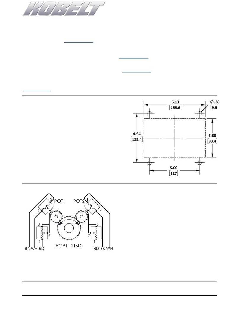
Diagram 4: Example of installation for rudder movement 35°-0-35°
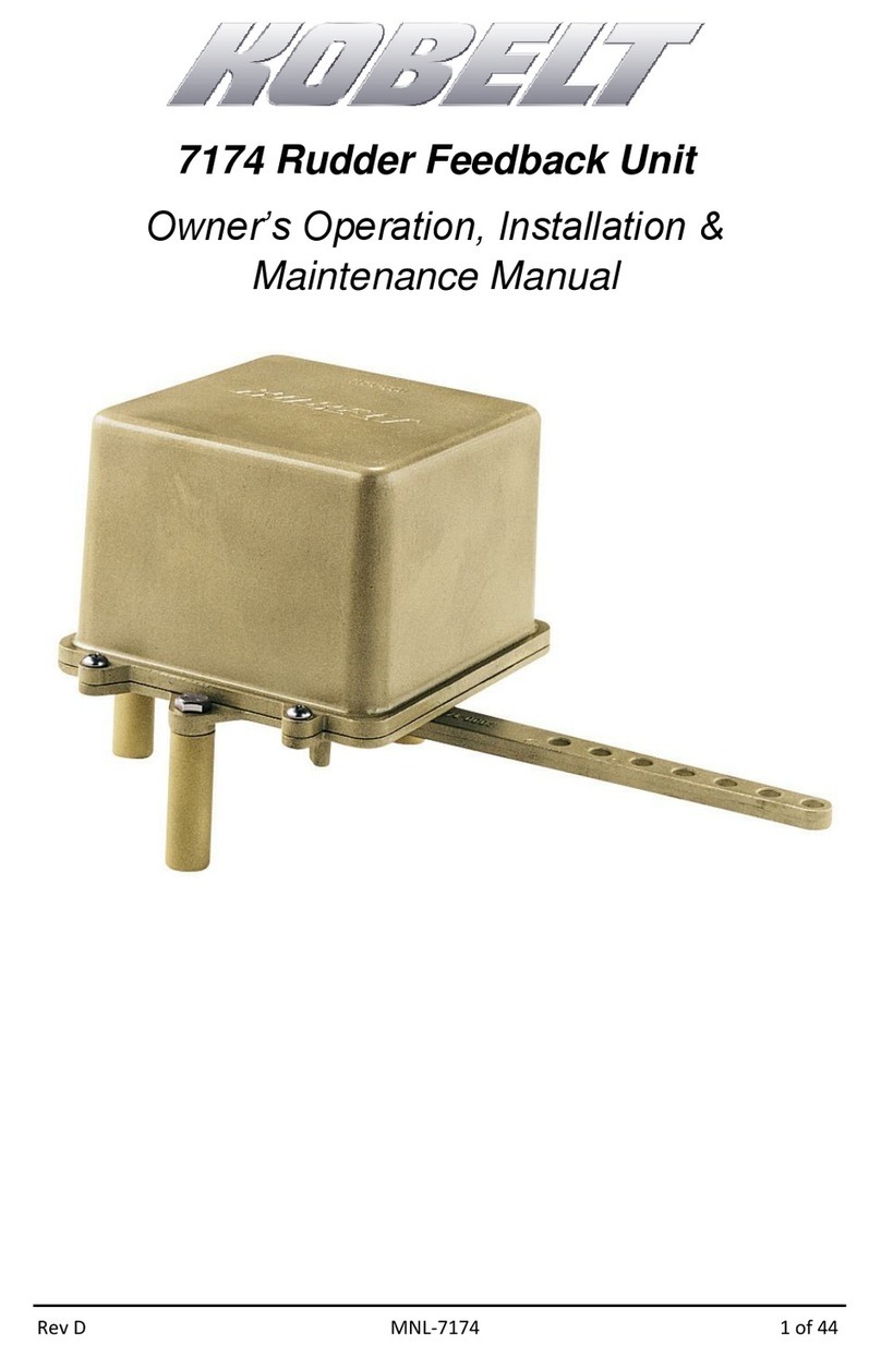
1. Determine the length of the connecting linkage to be used according to space available for
installation of the rudder angle feedback unit (model 7174). An example of the positions and
locations of connection point are as shown in diagrams 3 and 4. The actual position will depend on
factors such as available space and size of tiller. Ensure that there is no interference on either
equipment throughout the full range of movement. For questions or help on other installation
positions, please consult the dealer or Technical Support Department at Kobelt Manufacturing.
2. Secure the rudder angle feedback unit horizontally on a flat surface at a distance consistent with the
length of the connecting link.
3. With the feedback unit lever in the centre position, secure the connecting link to the lever arm at the
appropriate connection hole.
4. Secure the fasteners on both ends.
5. Ensure there is no obstruction in the movement of both tiller and feedback unit arms.
6. Calibrate the 7174 feedback unit for its full range of lever arm travel after installation.
