ASTRO U159 User manual

Version 10-2018A

Contents
Operating Manual U 159 - Version 10-2018Apage 2
Contents
Before starting operation of the device......................................................................................page 03
Symbols and conventions used.................................................................................................page 03
Proper use.................................................................................................................................page 04
Target group of this manual ......................................................................................................page 04
Device description .....................................................................................................................page 04
Important safety information......................................................................................................page 06
Warranty conditions...................................................................................................................page 07
Disposal.....................................................................................................................................page 08
Performance description ...........................................................................................................page 08
Connecting and installing the module .......................................................................................page 09
Quick start – starting operation of the U 159.............................................................................page 12
“Status” menu............................................................................................................................page 18
“IP Interfaces” menu..................................................................................................................page 21
“Network” menu.........................................................................................................................page 22
“IP RX Channels” menu ............................................................................................................page 24
“TS Multiplexer” menu ...............................................................................................................page 26
“RF Settings” menu ...................................................................................................................page 36
“RF Channels” menu .................................................................................................................page 37
“TS Processing” menu...............................................................................................................page 39
“NIT” menu ................................................................................................................................page 40
“LCN” menu...............................................................................................................................page 42
“User Settings” menu ................................................................................................................page 43
“TLS Settings” menu .................................................................................................................page 44
“Licensing” menu.......................................................................................................................page 45
“Configuration” menu.................................................................................................................page 46
“Update” menu ..........................................................................................................................page 47
“Logging” menu .........................................................................................................................page 49
“Active Alarms” menu ................................................................................................................page 50
“Statistics” menu........................................................................................................................page 51
“U 100” menu ............................................................................................................................page 52
“Documentation” menu..............................................................................................................page 52
Troubleshooting.........................................................................................................................page 53
Maintenance and repair.............................................................................................................page 53
Servicing....................................................................................................................................page 53
Technical data ...........................................................................................................................page 54

page 3
Before starting operation of the device
Operating Manual U 159 - Version 10-2018A
Before starting operation of the device
HINWEIS: Read this operating manual attentively! It contains important information about
installation, ambient conditions and maintenance of the device. Keep this operating manual for
future use and for handover in the event of a change of owner or operator. A PDF version of this
manual is available to download on the ASTRO website (there may be a more recent version).
The ASTRO company confirms that the information in this manual was correct at the time of
printing, but it reserves the right to make changes, without prior notice, to the specifications, the
operation of the device and the operating manual.
Symbols and conventions used
Symbols used in these instructions
Pictograms are visual symbols with specific meanings. You will encounter the following pictograms in
this installation and operating manual:
Warning about situations in which electrical voltage and non-observance of the instructions in this
manual pose a risk of fatal injuries.
Warning about various dangers to health, the environment and material.
Recycling symbol: indicates components or packaging materials which can be recycled (cardboard,
inserts, plastic film and bags). Used batteries must be disposed of at approved recycling points.
Batteries must be completely discharged before being disposed of.
This symbol indicates components which must not be disposed of with household rubbish.
Copyright information
Parts of the software used with this product originate from third-party vendors and were developed
under a variety of licensing conditions. Detailed information on the licences can be found on the
device's web user interface. If you select the menu item “Licensing” on the web browser interface of
the device, you will find a link to a page with detailed information.
You can obtain the source code for licence-free parts of the software upon request and against
payment of a processing fee.
Please contact us at:
ASTRO Strobel Kommunikationssysteme
Olefant 1-3
D-51427 Bergisch Gladbach (Germany)
Phone: (+49) 2204 405-0
All other parts of the software used with this product are subject to the copyright owned by ASTRO
Strobel GmbH.

Proper use
Operating Manual U 159 - Version 10-2018Apage 4
Proper use
The devices of the U 1xx- and U 2xx series are only used for converting signals of different modulation
to / from IP data streams in multimedia cable networks. The power supply unit U 100 SNT eco / U 100
SNT eco+ may only be used for the power supply of the U 1xx- and U 2xx units within the base unit
U 100-230. Modification of the devices or use for any other purpose is not permitted, and will immedi-
ately void any guarantee provided by the manufacturer.
Target group of this manual
Installation and starting operation
The target group for installation and starting operation of the ASTRO headend technology are qualified
experts who have training enabling them to perform the work required in accordance with EN 60728-11
and EN 60065. Unqualified persons are not allowed to install and start operation of the device.
Device configuration
Target group for the configuration of the ASTRO headend are persons who have received instructions
and have training enabling them to perform a configuration. Knowledge of EN 60728-11 and EN 60065
is not necessary for configuration.
Device description
The delivery is comprised of the following parts:
U 159 Edge QAM module and backplane
Operating manual
The U 159 plug-in module and the U 100 base unit feature a CE marking. This confirms that the prod-
ucts comply with the relevant EC directives and adhere to the requirements specified therein.
Figure 1, top:
U 159, installed in the U 100 base unit
(fitted with three plug-in modules)
Figure 1, middle:
U 159, front panel
[1] Display for management IP addresses,
data IP addresses, status messages, etc.
[2] Status display
[3] Control and data knob, menu switch
Figure 1: U 159
1
2
3

page 5
Device description
Operating Manual U 159 - Version 10-2018A
HINWEIS: Turning the data knob [3] (fig. 2, above) allows you to navigate through the indi-
vidual menu items in the U 159 display. Press the data knob to switch on the display.
The ASTRO logo will be the first display to appear following activation.
Turning the data knob clockwise allows to you access the individual displays:
Management A / B: The data for both management ports is displayed.
Status: The current hardware status and software status are both displayed.
Active alarms: The current error messages are displayed.
Licences: The licences currently installed are displayed.

Important safety information
Operating Manual U 159 - Version 10-2018Apage 6
Important safety information
To avoid any potential risks to the greatest extent possible, you must adhere to the following safety
information:
ACHTUNG: Failure to observe this safety information may result in personal injury due
to electrical and thermal dangers!
Proper use
Only use the device at the approved operating sites and in the ambient conditions allowed (as
described in the following), and only for the purpose described in the section “Proper use”.
Before starting operation of the device
HINWEIS: Read this operating manual attentively! It contains important information
about installation, ambient conditions and maintenance of the device. Keep this operating
manual for future use and for handover in the event of a change of owner or operator. A PDF
version of this manual is available to download on the ASTRO website (there may be a more
recent version).
Check the packaging and the device for transport damage immediately. Do not start operation of
a device that has been damaged.
Transporting the device by the power cable may damage the mains cable or the strain relief, and
is therefore not permitted.
Installation and operation
The device may only be installed and operated by qualified persons (in accordance with EN
60065) or by persons who have been instructed by qualified persons. Maintenance work may only
be carried out by qualified service personnel.
The module can only be installed in U 100-230 and U 100-48 base units. The safety information
in the operating manuals of the base units must be obeyed in addition to the safety information
described in this manual.
The installation site must be planned in a way that prevents children from playing with the device
and its connections.
In order to prevent inadmissible operating statuses from occurring, only the components
described in this manual, or components approved by the manufacturer for the base unit, may be
used.
The ambient temperatures specified in the technical data must be complied with, even when
climatic conditions change (e.g. due to sunlight). If the device overheats, the insulation used to
isolate the mains voltage may be damaged.
The device and its cable may only be operated away from radiant heat and other sources of heat.
To avoid trapped heat, ensure there is good ventilation on all sides (minimum interval of 20 cm to
other objects). Installing the device in a niche or covering the ventilation openings is not permitted.
The device does not feature protection against water and may therefore only be operated and
connected in dry rooms. It must not be exposed to splash water or drip water, condensation or
similar effects of water, as this may impair the isolation from the mains voltage.
Do not install the unit in locations with excessive dust formation, as this may impair the isolation
from the mains voltage.
Electromagnetic compatibility (EMC)
In order to avoid malfunctions from occurring when operating radio and telecommunications equip-
ment, as well as other operating units or broadcasting services, the following points must be observed:
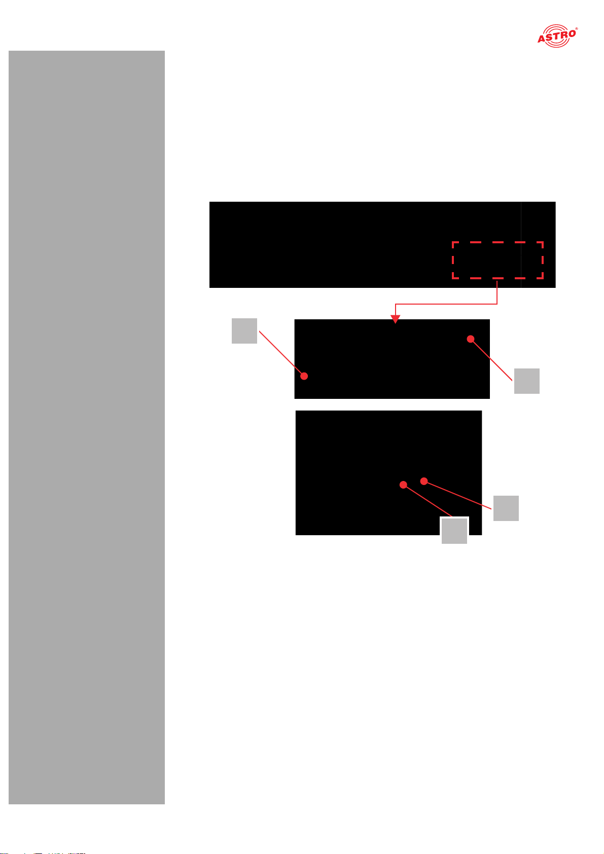
Before installation, the device must be checked for mechanical damage. Damaged or bent covers
or housings may not be used.
During operation, the device must always be covered by the components provided for this
purpose. Operation with an opened cover is not permitted.
The braided line or the contact springs may not be damaged or removed.

page 7
Warranty conditions
Operating Manual U 159 - Version 10-2018A
Maintenance
The operating display only shows whether the DC current, which supplies the device components,
has been disconnected. However, operating displays (on the power supply unit or the device) that
are not lit up in no way indicate that the device is completely disconnected from the mains. There
may still be voltages in the device that are dangerous to touch. You may therefore not open the
device.
Read carefully: EN 60728-11 – Part 1, Safety requirements / No service tasks during electrical
storms!
Repair
Repairs may only be performed by the manufacturer. Improperly performed repairs may result in
considerable dangers for the user.
If malfunctions occur, the device must be disconnected from the mains and authorised experts
must be consulted. The device may need to be sent to the manufacturer.
General information
Store or use the device in a safe location, well out of reach of small children. It may contain small
parts that can be swallowed or inhaled. Dispose of any small parts that are not needed.
Plastic bags may have been used for packaging the device. Keep these plastic bags away from
babies and children in order to avoid any danger of suffocation. Plastic bags are not toys.
Do not store the device near chemicals or in places in which a leakage of chemicals may occur.
Organic solvents or fluids in particular may cause the housing and/or cables to melt or disintegrate,
presenting a danger of fire or electric shock. They may also cause device malfunctions.
Warranty conditions
The general terms and conditions of ASTRO Strobel GmbH apply. You will find these in the current
catalogue or on the Internet under “www.astro-kom.de”.
Disposal
All our packaging materials (cardboard boxes, insert sheets, plastic films and bags) are fully recyclable.
After use, this device must be disposed of as electronic waste in an orderly manner according to the
current disposal regulations of your district / country / state.
ASTRO Strobel is a member of the Elektro system solution for the disposal of packaging materials. Our
contract number is 80395.
Performance description
The U 159 is a plug-in module that is only intended for use in the base units
U 100-230 and U 100-48. It can receive up to 1024 MPEG data streams encapsulated in accordance
with Internet Protocol (IP). These are converted in up to 64 QAM channels and are output using the
two HF outputs in the U 159.
To use the devices properly, read the following safety and operating instructions attentively.
The U 159 plug-in module features the following performance characteristics:
Conversion of up to 1,024 IP gigabit Ethernet multicast groups
QAM signals are fed out in 64 channels
Outstanding output parameters provided by Direct Digital Technology

Connecting and installing the module
Operating Manual U 159 - Version 10-2018Apage 8
Connecting and installing the module
HINWEIS: The instructions for the base unit U 100 include a description of how to prepare
the base unit for installation.
Observe that you need to insert an SD memory card into the module prior to installation in the
base unit (see figure at left)
Coding and installing the backplane
A backplane is included with every U 1xx signal converter. This is used to establish a mechanical
connection between the signal converter and the base unit. Both the mains HF connections and the
network connections are connected to this
backplane.
To ensure the position of the backplane, and therefore the position of the respective signal converter
in the U 100 base unit, is correct, you must plug a corresponding control dial onto the circuit board on
the backplane. Proceed as described in the following.
[1] Left slot
[2] Middle slot
[3] Right slot
Figure 2: Coding the backplane
123
1
2
3

page 9
Connecting and installing the module
Operating Manual U 159 - Version 10-2018A
To prepare the backplane for installation, proceed as follows:
Turn the control dial to the position required for the intended installation position in the way it is shown
in figure 2.
HINWEIS: A control dial that has not been correctly set to correspond to the installation
position will result in incorrect LED displays on the front of the U 100 base unit (see section
“Device description”). Furthermore, the correct position cannot be displayed on the web
browser user interface.
[1, 2] Phillips-head screws
[3] Cable for signal supply
[4] Cable for power supply
You can now install the backplane in the base unit. To do so, proceed as follows:
Figure 3: Installing the backplane in the base unit
3
4
1
2

Connecting and installing the module
Operating Manual U 159 - Version 10-2018Apage 10
AUFGABE
1. When the U 100 base unit is in its delivery state, the three installation slots for the backplanes are
covered by dummy plates (see figure 3, above). Start by removing the Phillips-head screws [1] and
[2] from the dummy plate at the required installation position (left, middle or right) and remove the
dummy plate.
2. You can now see the two connection cables for the selected slot (power supply and signal cable).
Connect the cables to the backplane as shown in figure 3 (above).
3. Now carefully insert the backplane into the slot of the U 100. Make sure the cables are not jammed.
You can push the backplane into the housing by applying light pressure.
ERGEBNIS:
The backplane is now connected and installed. Once installed, it should correspond to the figure at the
left.

page 11
Quick start – starting operation of the U 159
Operating Manual U 159 - Version 10-2018A
Quick start – starting operation of the U 159
Connecting the U 159 to a PC or laptop
To be able to configure the U 159, you now need to connect the network sockets (Management A or
Management B) on the backplane of the device (see figure at left) to your PC or laptop using a
network cable.
Once you have connected the base unit to the power supply, the U 159 will switch on automatically.
Once it has booted (approx. 90 seconds), the ASTRO logo initially appears in the display.
Turn the knob to the right of the display clockwise until the menu item “Interface settings” is displayed.
The two management IP addresses (Management A and Management B) for the device now appear in
the upper lines.
Make a note of the address of the management connection which you are using for your PC or laptop
to ensure you can enter this in the address line of your web browser later on.
HINWEIS: Please note that your PC or laptop must be in the same sub-network as the
U 159! The sub-network mask of the U 159 is set to 255.255.205.0 upon delivery. The PC or
laptop which is connected must therefore be assigned an IP address with the following structure:
172.23.xx.yy (whereby the digits for xx and yy depend on the MAC address)
Net mask: /16
You can now start the configuration using the web browser user interface.
General information on the structure of the web browser interface
The configuration interface is divided into the following sub-areas:
Figure 4: Structure of the web browser interface
Status line (header) [1]: Displays general information on the module.
SW: Software status
FW: Current version of the software installed
HW: Hardware version
Up: Runtime since the system was booted
Time: Date and time
Name, location, contact: corresponds to the settings which were made in the configuration area
Navigation menu [2]: Displays the individual configuration areas which you can select by clicking
the mouse. A detailed description of these areas can be found on the following pages of this
chapter.
Content area [3]: The respective configuration form – depending on the menu item selected – is
displayed here.
HINWEIS: The browser display is not updated automatically. Use the corresponding button
in the menu of your browser to update the display.
1
2
3

Quick start – starting operation of the U 159
Operating Manual U 159 - Version 10-2018Apage 12
Logging in
To log in, enter the IP address of the U 159, which appears in the device display, in the address line of
the browser. The menu page “Status” will then appear. Select the item “Log in” from the navigation
menu at the left. The input mask for the log in should then appear (see figure 6, below). In delivery state,
you must use the following log-in data:
User name: “user” or “admin” (input without inverted commas)
Password: astro
Figure 5: Log in
After logging in, the start page of the U 159 with all relevant system information will appear. The navi-
gation menu and the log-in status display will appear at the left.
Only one user can be logged into the user interface of the U 159 at a time. The current user is displayed
in the column at the left, below the menu.
The device status is indicated by a green or red circle. If a green circle is displayed, the device is op-
erational. If the circle is red, then a fault has occurred.
A list of current errors is available under the menu item “Active alarms”.
HINWEIS: For security reasons, you should change the access data valid upon delivery (user
name and password) to prevent unauthorised access!
The procedure is described in the section “Changing user data”.
Changing the IP address
HINWEIS: If you wish to change the IP address, then the settings on the PC must be changed
accordingly. IP addresses can only be changed by the administrator!

page 13
Quick start – starting operation of the U 159
Operating Manual U 159 - Version 10-2018A
Start by changing the IP addresses for the data port and the management. To do so, click on the item
“IP Interfaces” in the menu at the left. You will now see the following table in the content area:
Figure 6: “Data Interfaces” table
You can enter the IP addresses for the data ports A, B, C and D in the “IPv4 Address/Subnet” line. Make
sure that you activate the ports being used by activating the corresponding radio button in the “Active”
line. You can also enter IP addresses in the “IPv6 Address/Subnet” line. Entering values for IPv4 or
IPv6 only is also possible.
You can enter the IP addresses for both management ports in the “Management Interfaces” table fur-
ther down. Make sure that you activate the ports being used in this case as well by activating the cor-
responding radio button in the line “Active”.
Figure 6: Changing the IP address
To save your changes, click on the “Apply” button at the top in the header.
The signal flow in the U 159
The overview on page 15 shows the possible signal paths for the U 159. The specific
signal flow can be divided into the following sub-areas:
The IP receivers receive a signal via data port A, B, C or D (each can be activated).

Quick start – starting operation of the U 159
Operating Manual U 159 - Version 10-2018Apage 14
Ethernet
SPF
Data C
1024
U159
IP
RX1
IP
RX256
IP
RX257
IP
RX512
IP RX
IP
RX513
IP
RX768
IP
RX769
IP
RX1024
+
RF
RF
A
mplifier
DAC RF
A
ttenuator
Modulator 1
Modulator 2
Modulator 64
-20dB
Data
A
Data B
Data D
...
...
...
...
...
64
Multiplexer
TS MUX

Quick start – starting operation of the U 159
page 15
Operating Manual U 159 - Version 10-2018A
Figure 7: The signal flow in the U 159

Quick start – starting operation of the U 159
Operating Manual U 159 - Version 10-2018Apage 16
Configuring the IP receiver
Now start configuring a signal path in the U 159. Start by clicking on the item “IP RX Channels” in the
web browser interface menu. You will now see the following tables:
Figure 8: Setting the source for the data stream and activating the connection to the data port
Enter the IP address and the port for the data stream in the “Adding/Deleting of IP RX Channels”
table. Optionally, you can also enter a source select address in the“Source Address” input field.
Important: Activate the checkbox in the “Add TS Channel” column.
Activate the “add channel” checkbox in the TS Multiplexer column.
Please keep in mind that you must create an output in order to route any other signals (see section
“Configuring output channels”, page 17).
Now click on the plus symbol to activate the reception channel. The channel should now appear in the
“IP RX Settings” table.
Checking the data reception rate
Now click on the menu item “Status” in the menu at the left. You will then see the following overview:
Figure 9: Displaying reception statistics
A data reception rate > 0 at data ports A, B, C or D should now appear in the “Payload Receive” line in
the “IP Interfaces” table.

page 17
Quick start – starting operation of the U 159
Operating Manual U 159 - Version 10-2018A
Configuring HF output channels
Start by defining the required number of output channels, the maximum overall level and the channel
spacing. To do so, click on the item “RF Settings” in the menu at the left. You will now see the following
table:
Figure 10: “RF Main Settings” table
You can select the required value from the drop-down list in the “Value” column in the “Used RF chan-
nels” line.
You can enter the required level in the input field in the “Channel Power” line.
You can select the required channel spacing from the drop-down list in the “Current Channel Grid” line.
To save your changes, click on the “Apply” button at the top in the header.
To complete the process, you should configure and activate the HF output channels. To do so, click on
the menu item “RF Channels” in the web browser interface menu. You will now see the following table:
Figure 11: Configuring HF output channels
Add a channel as an example by selecting a value for the QAM modulation from the drop-down list
“Modulation” in the “Adding/Deleting of RF Channels” table, and then selecting a channel frequency
from the drop-down list “Channel”. Now activate the “Enable” checkbox and click on the plus symbol.
The channel should now be listed in the “RF Channel Settings” table. You then still need to select the
required transport stream.
To save your changes, click on the “Apply” button at the top in the header.
HINWEIS: More information on setting the HF modulators can be found in the sections “RF
Settings” menu and “RF Channels” menu.

“Status” menu
Operating Manual U 159 - Version 10-2018Apage 18
“Status” menu
To have the current settings for the U 159 displayed, click on the item Status in the menu at the left.
You can now see the overview shown in figure 12:
Figure 12: Status display
The following tables are displayed:
Set data and status of the IP interfaces:
Figure 13: Status display – IP interfaces
The values for the following parameters are displayed and configured here respectively in accordance
with the six connections on the backplane of the U 159 (Data A, Data B, Data C, Data D, Management
A and Management B, see section “Device description”):

page 19
“Status” menu
Operating Manual U 159 - Version 10-2018A
MAC: MAC address of the respective interface
IPv4-Addr./Net: IPv4 address (left field) / sub-network (right field)
IPv6-Addr./Net: also supports: IPv6 address (left field) / network (right field)
Status: switched off (off) or active (transmission rate is displayed); when using 1000base-x SFP
modules, this is only the link to the module
OS Transmit: Data rate in transmit direction, generated by the operating system
OS Receive: Data rate in receive direction, generated by the operating system
Total Receive: Total data rate in receive direction, gross (OS + payload)
Payload Receive: User data rate in receive direction, net
Status display of the IP reception channels:
Figure 14: Status display – IP RX channels
The up to 32 reception channels routed to a data port are each represented by a square in the “IP RX
Channels” table. Depending on the status of a channel, the square either appears in green (no errors)
or in red (error has occurred). If the cursor is held over one of the squares, a pop-up window with infor-
mation about the respective channel appears. In the event of an error, several parameters can also be
shown.
Status display of the HF output channels:
Figure 15: Status display – RF channels
The up to 64 QAM output channels are each represented by a square in the “RF Channels” table. De-
pending on the status of a channel, the square either appears in green (no errors) or in red (error has
occurred). If the cursor is held over one of the squares, a pop-up window with information about the
respective channel appears. These are specifically:
RF Channel: Channel frequency
Max. data rate: Maximum transmission rate (used + null)
Used data rate: Effective load
Null data rate: Null packets
Utilization: Used data rate / max. data rate (in %)
HINWEIS: Inactive channels are marked in grey!
The following information can also be found in the lower line:
Calculated power: Calculated output power (specified in dBµV)
Measured power: Output power measured at the HF socket (specified in dBµV)
Termination mismatch: Power difference due to a fault in the output end of the cable
(specified in dB)

“Status” menu
Operating Manual U 159 - Version 10-2018Apage 20
Status messages on monitoring:
Figure 16: Status display – monitoring
The “Monitoring” table allows a series of hardware functions to be monitored; specifically, these are:
Temperature front: Temperature displayed in °C for the mainboard
Temperature center: Temperature displayed in °C for the mainboard
Temperature preamp: Temperature displayed in °C for the preamplifier
Temperature DAC: Temperature displayed in °C for the converter
Temperature backplane: Temperature displayed in °C for the HF output stage
Fan: Fan rotation speed
Voltage XX: Supply voltage XX in volts
Current XX: Current in A for the corresponding supply voltage
U 100 voltage supply:
Figure 17: Status display – U 100 power supply
The respective values for the power supply, fan and temperature of the two U 100 power modules is
displayed in the “U 100 power supply” table. If only one power module is installed, then the information
“not fitted” appears for the second power module.
Table of contents
Other ASTRO Media Converter manuals