ATB AQUAmax BASIC series User manual

Innovations for clean water
AQUAmax®BASIC / CLASSIC
Operation and maintenance manual


Operation and maintenance manual AQUAmax®BASIC/CLASSIC
ATB WATER GmbH, Südstraße 2, D-32457 Porta Westfalica, www.atbwater.com /
Art.-No.: 9060 0210 / Status: 30.01.2019 / Page 3 from 40
Contents
General and safety information…………………………… .......................................... 4
Functional description........................................................................................ 6
Control unit ATBcontrol© 3 ................................................................................... 8
General information on operation.................................................................... 9
Commissioning .............................................................................................. 10
Main level...................................................................................................... 12
Logbook .................................................................................................... 12
Settings..................................................................................................... 13
Service Mode............................................................................................. 15
Manual operation / Info .............................................................................. 16
Date/Time / Language / Error Reset ............................................................ 17
Pre-set Parameters........................................................................................ 18
Current limiting values ................................................................................... 19
Error messages ............................................................................................. 19
UVS®............................................................................................................ 19
USB-connection............................................................................................. 20
Control Circuit Board / Fuses.......................................................................... 20
Potential-free Contact .................................................................................... 21
Configuration of the Connection Socket........................................................... 21
Technical Data .............................................................................................. 20
Information on routine maintenance .................................................................... 24
Self-monitoring by the operator .......................................................................... 25
Information on disposal...................................................................................... 26
Rectification of faults ......................................................................................... 27
Important data for fault diagnosis of the electrical units ....................................... 29
Operations diary ................................................................................................ 30
CE documentation / Declaration of performance .................................................. 30
EC Declaration of Conformity ............................................................................. 38
Dear customer,
At this point we would like to thank you for the trust which you have shown with the purchase of
this product.
On the following pages you will find everything necessary about the ioperation and the
maintenance requirements of your AQUAmax®small wastewater treatment plant.
Please observe that the maintenance are very important for a good treatment performance.

Operation and maintenance manual AQUAmax®BASIC/CLASSIC
ATB WATER GmbH, Südstraße 2, D-32457 Porta Westfalica, www.atbwater.com /
Art.-No.: 9060 0210 / Status: 30.01.2019 / Page 4 from 40
General and Safety Information
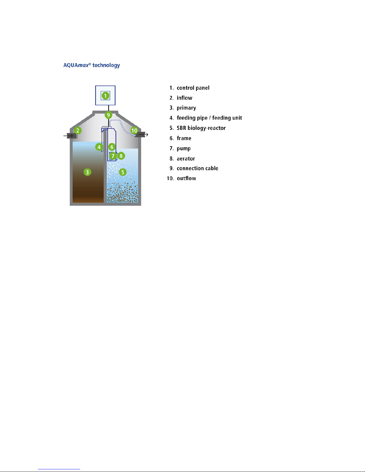
With the AQUAmax®one is concerned with a technical system which, in combination with a multi-
chamber tank, is employed as small wastewater treatment plant for the aerobic biological treatment
of domestic and comparable wastewater of up to 75 PE from single or several buildings.
Dimensioning, design and operation are to take place up to 50 PE in accordance with EN 12566-3.
With employment in accordance with regulations no hazards whatsoever emanate from the plant. If
the AQUAmax®is used for other purposes without the explicit approval of ATB WATER GmbH
and/or the following safety information is ignored, this can lead to the hazarding or injury of
persons and to malfunctions or defects in the plant. In this case any liability is excluded,
Modifications to the plant or unauthorized conversion is not permitted.
The AQUAmax®and accessories are not intended to be used by persons (including children) with
limited physical, sensory or mental capabilities or due to a lack of experience and/or knowledge,
unless they are supervised by or receive instruction from a person responsible for their safety, as
to how the AQUAmax®and accessories are to be used. Children are to be supervised in order to
ensure that they do not play with them.
Before use the AQUAmax®is to be installed correctly and in agreement with the installation
instructions. Installation instructions, operating and maintenance instructions are to be read
thoroughly and the instructions included therein are to be followed implicitly.
With assembly and installation, commissioning and operation as well as, if required,
decommissioning, national standard specifications and regulations are to be complied with. All
tasks may be carried out by trained and qualified specialists with appropriate certificate of technical
qualification. The operator is to be instructed by the fitter.
With the connection of the control system the national applicable regulations and the details on the
type plate are to be complied with (mains voltage, frequency etc.). The equipment is to be operated
on a network which includes a protective earth conductor (PE). Attention is to be paid to correct
phase connection (even with plug-in design)! The connection to the mains must take place by
means of separate fusing and residual current protective circuit breaker. Before commissioning,
the correct function of the electrical protective measures must be checked!
The installation work is to be carried out by qualified electricians only. With work on the equipment
fundamentally the mains plug is to be disconnected. A separation or extension of the cable is not
permitted. The electrical connection data is to be taken from the type plate on the equipment.
Operate no equipment which has a damaged connector/connection cable or plug, which indicates
a malfunction, has been dropped or has been damaged in any way.
With all maintenance and repair work the plant is to be disconnected from the mains. The
AQUAmax®can be removed easily from the tank. If the plant is to be climbed into, this may take
place only with the presence of a second person (this is fundamental!). Particular care is to be
taken. The applicable accident prevention regulations and rules of technology are to be complied
with.
In the versions with submersible aerator the AQUAmax®feeds the required air to the wastewater
through a rapidly rotating propeller. Never work in the vicinity of the aerator as long as the
AQUAmax®is connected with the mains. Danger of injury!
The correct function can only be guaranteed with the employment of original spare parts or spare
parts approved by ATB. Before commissioning, all points of the operating instructions are to be
checked. Keep these instructions readily to hand at all times!

Operation and maintenance manual AQUAmax®BASIC/CLASSIC
ATB WATER GmbH, Südstraße 2, D-32457 Porta Westfalica, www.atbwater.com /
Art.-No.: 9060 0210 / Status: 30.01.2019 / Page 5 from 40
Explanation of the warning notices used:
Attention! Danger due to electrical voltage!
Rotating parts. Danger of crushing and being drawn into the area of the submersible aerator!

Operation and maintenance manual AQUAmax®BASIC/CLASSIC
ATB WATER GmbH, Südstraße 2, D-32457 Porta Westfalica, www.atbwater.com /
Art.-No.: 9060 0210 / Status: 30.01.2019 / Page 6 from 40
Functional Description
The wastewater treatment plant works according to the activated sludge principle using the
retention process (single tank or SBR plant). With this, the contaminants from the wastewater are
taken up by suspended micro-organisms (activated sludge) and converted into biomass.
The wastewater first reaches the coarse interceptor. Every 2 hours – according to the principle of a
communicating pipe and with the aid of an excess sludge pump – the retained wastewater is fed
into the aeration stage. The aeration takes place intermittently via a submersible motor aerator or
with a compressor and membrane tube diffusers on the tank bottom (CLASSIC ZB).
After 6 hours the aeration phase ends and the settling phase begins.
After 2 hours settling time the treated wastewater is pumped out using the clarified water pump.
The switch-off point is determined via a float switch. If, as a result of a pump defect, this minimum
water level is not achieved an alarm is triggered. After ca. 8 hours, with the end of the clarified
water removal, the cycle is ended and a new one begins.
The control unit can be matched to the respective requirement case. With commissioning the plant
is set to the maximum number of persons connected. A modification of this setting is not required
with short-term over or underloading.
The plant achieves its full treatment performance after a run-up period of ca. one month. With more
extreme underloading or temperatures under 12° C it can also take longer until the biology has
developed completely. In this case it is recommended to seed using activated sludge in order to
accelerate matters.
With the AQUAmax®BASIC charging, removal of excess sludge and the drawing off of clarified
water take place using only one pump. The water streams with this are fed into the individual areas
using a patented hydraulic system.
*alternatively membrane tube diffuser on the tank bottom
*

Operation and maintenance manual AQUAmax®BASIC/CLASSIC
ATB WATER GmbH, Südstraße 2, D-32457 Porta Westfalica, www.atbwater.com /
Art.-No.: 9060 0210 / Status: 30.01.2019 / Page 7 from 40
Holiday / energy-saving operation
If, over a period of more than 4 hours, no wastewater flows into the plant, then the system switches
automatically into the energy-saving holiday operation. The aeration time is reduced to the point
that the micro-organisms just have sufficient oxygen available. With normal loading the plant
switches back into the operating mode set.
Sampling
As the pumping out process is of a short duration only, the treated water is collected into a suitable
container in the filtering tank (accessory: 1.5 l sampling bottle). The container is mounted in the
vicinity of the cover and is thus easily accessible from above.
Alternatively a container can be deployed in a separate sampling shaft.
Installation and dimensioning
Dimensioning and statutory installation conditions are described in more detail in the German
National General Technical Approval.
Operation and maintenance
Small wastewater treatment plants must be checked by the operator at certain intervals as well as
being serviced twice a year by a specialist. Both are important for a correct operation of the plant.
The sludge removal of the primary settling stage takes place, depending on utilisation, once a year
or as required.
Further details on this can be taken from the corresponding chapter.
Application possibilities
The AQUAmax®is conceived for the treatment of domestic wastewater. The following may not be
fed to the small wastewater treatment: commercial/trade wastewater (insofar as it is not
comparable with domestic), infiltration water (e.g. drainage water), cooling water, runoff water from
swimming pools, precipitation water.
Technical data
The AQUAmax®consists of the following electrical units:
•1 (BASIC) or 2 submersible pump(s)
•1 or 2 submersible motor aerator(s)
or compressor(s)
•1 float switch (BASIC and CLASSIC 1-16
integrated)
•1 control unit
The units are designed for 230V, 50 Hz.
In addition, the AQUAmax®consists of a carrier frame, pipelines and hoses.
The electrical components are subjected to systematic wear. In individual cases these components
must be exchanged after 2 years. The service life of the units, from experience, lies between 5 and
10 years.
Treatment performance
The AQUAmax®meets the following limiting values (with standard conditions and correct
operation):
•BOD5: 20 mg/l
•COD: 90 mg/l
•NH4N (>12°C): 10 mg/l
•N
tot: 25 mg/l (>12°C)
Modular system
In combination with the control unit proControl©the AQUAmax®BASIC or AQUAmax®CLASSIC
forms the basic framework for the phosphate removal and UV disinfection (CLASSIC only).

Operation and maintenance manual AQUAmax®BASIC/CLASSIC
ATB WATER GmbH, Südstraße 2, D-32457 Porta Westfalica, www.atbwater.com /
Art.-No.: 9060 0210 / Status: 30.01.2019 / Page 8 from 40
Control unit ATBcontrol© 3
Control unit for the activation of small wastewater treatment plants of the types AQUAmax®BASIC
/ CLASSIC and AQUAPRIMO
General and safety information
With intended employment of the equipment no hazards whatsoever emanate from the unit.
National applicable regulations and technical data are to be observed.
Should the ATBcontrol© 3 be used for other purposes without the express approval of ATB WATER
GmbH and/or if the following safety information is disregarded, this can lead to malfunction of or
defects in the plant. In this case any liability is ruled out.
Modifications to the unit are not permitted and lead to the loss of all claims under warranty.
Do not operate any unit which indicates malfunctions, has been dropped or is damaged in any
way.
Features
•Microprocessor controlled
•USB connection for data readout and input
•Splash water protected. Conditionally suitable for outside areas (IP54)
•Wall mounting
•Voltage failure detection system (UVS®)
•Potential-free contact for an additional alarm facility
•Simple and rapid operation
•Times for all parameters completely pre-programmed
•Automatic run-in phase with suppression of excess sludge removal
•Parameter settings freely selectable
•Alarm interval
•Alarm volume adjustable
•Deployable for AQUAmax®BASIC / CLASSIC and AQUAPRIMO
•Plug-in
•Winter operation and sludge removal mode for the reduction of the aeration times

Operation and maintenance manual AQUAmax®BASIC/CLASSIC
ATB WATER GmbH, Südstraße 2, D-32457 Porta Westfalica, www.atbwater.com /
Art.-No.: 9060 0210 / Status: 30.01.2019 / Page 9 from 40
General information on operation
The operation of the control unit takes place via three short-stroke keys. By pressing a key the
display illumination is switched on (lapses if no key is operated within 5 minutes).
Key functions:
↑↓ Scroll upwards or downwards / menu selection
OK Transition of cursor to the character, which is to be changed / value input is saved /
selection of menu point / menu setback.
With temperatures below 0°C a severely limited function of the LC display is to be anticipated.
The ATBcontrol© 3 is supplied as plug-in variant. Cabling on site is dispensed with.
All tasks, which nevertheless require an opening of the control unit, are to be carried out by
a qualified electrician!
ATTENTION! Before opening the ATBcontrol© 3 and/or the connection box it/they
must be disconnected from the mains supply. Work on opened units may be
carried out exclusively by qualified electricians! Pay attention to phase-correct
connection (even with plug-in design)!
As you are concerned with an electrical plant with submerged motor units, a
separate B16 fuse and a (separate) upstream 30 mA ELCB (earth leakage circuit
breaker) is absolutely essential!
Attention is to be paid to correct laying of the protective earth conductor up to the
earthing of the building.

Operation and maintenance manual AQUAmax®BASIC/CLASSIC
ATB WATER GmbH, Südstraße 2, D-32457 Porta Westfalica, www.atbwater.com /
Art.-No.: 9060 0210 / Status: 30.01.2019 / Page 10 from 40
Commissioning
With first commissioning basic settings and tests are carried out. Please ensure that all information
for this is available. With input of the plant values all important parameters are pre-set. However,
we recommend that, following commissioning, the parameters are again checked under
Settings, as false values can, inter alia, lead to an increased power consumption.
In the Service Mode you have the possibility later of undertaking modifications.
Language selection
Enter language you need.
Password input
Please enter the six-figure code number.
Date and time
Enter the date and time.
Important for the correct entries in the logbook
Selection of the plant type
Select between BASIC, CLASSIC or AQUAPRIMO.
Number of inhabitants
Select the connected PT.
The settings belonging to the number of inhabitants are carried out
automatically.
Serial number
Enter the serial number, which is located on the frame of the AQUAmax®
(not the serial number of the control unit), here. Please ensure that the serial
number is entered right-aligned, in order that leading zeros result.

Operation and maintenance manual AQUAmax®BASIC/CLASSIC
ATB WATER GmbH, Südstraße 2, D-32457 Porta Westfalica, www.atbwater.com /
Art.-No.: 9060 0210 / Status: 30.01.2019 / Page 11 from 40
New plant?
With yes the sludge return feed is suppressed for half a year (run-in phase).
Test run
In test run operation the current float level and the current power input are
indicated. Pressing OK carries out the test run.
With this make absolutely sure that no one is working in the danger area of the
running submerged aerator!
The individual units are taken into operation for 4 seconds and are checked for overload and/or
underload. If the minimum permitted value is undercut or the maximum permitted value is
exceeded a warning signal results.
By manual switching of the float switch (BASIC / CLASSIC: submerging in or removing from the
water) the test run can be repeated and concluded.
AQUAmax®BASIC and CLASSIC are equipped with the AQUAswitch©. With this you are
concerned with a reed contact switch, which is integrated in the air intake line. The actual
float body cannot be seen from outside. For switching, the AQUAmax®has to be
submerged or removed or tilted.
The test run can be interrupted through OK.
Saving of the parameters
Have you made an incorrect input? By selecting no and OK the
commissioning can be repeated.
If the inputs are correct, confirm with yes and OK.
Float at the top =
Contact closed Float at the bottom =
contact open

Operation and maintenance manual AQUAmax®BASIC/CLASSIC
ATB WATER GmbH, Südstraße 2, D-32457 Porta Westfalica, www.atbwater.com /
Art.-No.: 9060 0210 / Status: 30.01.2019 / Page 12 from 40
Info indication / Current phase
A switchover to info indication now takes place. Indicated is the plant type,
the selected PT number, the software version and serial number of the
wastewater treatment plant type.
With this commissioning is completed. Should in the course of time a
necessity for an amendment to the settings arise, then the specialists have
the possibility of undertaking this in the Service Mode.
The current phase is indicated after ca. 5 minutes. By pressing ↑↓ you,
however, have the possibility of changing over again to info indication or to
the main level.
The indication of the current phase informs you about the current status of
the wastewater treatment plant. Indicated are the operating hours of the individual units, the
current cycle phase and its duration as well as the time. In the case of malfunction, in addition, the
fault which has occurred is indicated. By a single pressing of any key the background lighting is
activated lapses 5 minutes after the last operation of a key).
Main Level
In the main level you have the possibility, using OK, ↑↓ and OK again, of
accessing various sub-menus, which enables the acquisition of further
information, amendment of settings or moving into manual operation.
You leave the main level through ↑↓ until the point Return and OK.
Logbook
All relevant errors, run times, events and messages are lodged in the
logbook.
You access the individual points using ↑↓ and OK.
Errors
Recording of the error messages which have
arisen (max. 1000). An explanation of the
indicated messages can be found in the appendix.
Return using OK.
Run times
You can have the run times
shown in a weekly summary
and over the complete
operating time.

Operation and maintenance manual AQUAmax®BASIC/CLASSIC
ATB WATER GmbH, Südstraße 2, D-32457 Porta Westfalica, www.atbwater.com /
Art.-No.: 9060 0210 / Status: 30.01.2019 / Page 13 from 40
Events
Documentation of manual interventions (max.
1000). E.g. Changes of run times.
Return using OK.
Messages
Every change of status is documented here; e.g.
when the float switch has switched, when the
compressor has switched on and off (also whether
automatically or manually), failure of the mains
supply voltage.
Settings
All relevant settings can be reviewed here.
Modifications are, with the exception of the confirmation of a sludge removal
and of the signal tone, are possible in the Service Mode.
Operating parameters
feeding: specification of the feeding time (with
the BASIC the number of charging batches) for
the build-up of the communicating pipe between
coarse filter and sludge activation.
fed. pause: Time period between batches.
Deni phase: Duration of the denitrification
phase. The denitrification phase is component
part of the aeration phase and takes place
following the charging.
Deni aer. ON/OFF: Aeration times/pauses
during the denitrification phase.
Aer. phase: Duration of the complete charging phase.
ON/Off norm: Aeration times/pauses during the normal phase.
Aer. ON/OFF econ: Aeration times/pauses during the economy
phase.
sediment.: Duration of the settling phase.
CW evacuation: If the removal of the clarified water at the end of the
settling phase takes longer than the run time specified a flooding
warning takes place.
followup: As the AQUAswitch©has a very small switching hysteresis,
the clarified water pump still continues to run on for the set time after

Operation and maintenance manual AQUAmax®BASIC/CLASSIC
ATB WATER GmbH, Südstraße 2, D-32457 Porta Westfalica, www.atbwater.com /
Art.-No.: 9060 0210 / Status: 30.01.2019 / Page 14 from 40
reaching the actual float switch tripping point. Thus an inadvertent
“false” level signal caused by water movements is prevented.
Sl back: Time for the excess sludge removal. This takes place once
during a cycle, immediately following an aeration.
Flush pulse: In order to free the clarified water pump of activated
sludge, which has collected in the casing during the aeration phase,
the pump is operated during the settling phase for the time set (with the
BASIC the number of the charging batches). Through the short-term
build-up of a head of water and the subsequent subsidence, the sludge
is driven out of the casing.
run-in phase: During the listed number of days no excess sludge
removal takes place.
Current limits
Minimum/maximum current consumption of the
individual units below/above which an alarm
signal takes place.
Alarm pause
If errors occur within the selected time interval
(max. 12 hours), then the acoustic alarm is
emitted only after run-out of this time.
Sludge evacuation
With activation the aeration times are reduced by
20% for a period of six weeks (no further reduction
in winter operation).
Following successful activation this function is
blocked for six months.
Signal sound
Selection of the volume of the alarm sound.

Operation and maintenance manual AQUAmax®BASIC/CLASSIC
ATB WATER GmbH, Südstraße 2, D-32457 Porta Westfalica, www.atbwater.com /
Art.-No.: 9060 0210 / Status: 30.01.2019 / Page 15 from 40
Service mode
The access to the Service Mode takes place via a 6 figure code number,
which is made available exclusively to the authorised specialist firm.
In the Service Mode all parameters relevant and necessary for the
operation of the wastewater treatment plant are set and changed. Please
note that false inputs can lead to a faulty process!
The inputs are not checked for plausibility! ATB WATER
GmbH rejects any claims under warranty for the results of
inappropriate inputs!
Our service department will be very happy to provide you
with support.
Operating parameters
With the selection of the PT number with
commissioning, the parameters lodged in the
memory are loaded. At this point you have the
chance of carrying out modifications. For
description of the individual points see above
(Settings).
Product type
Selection of the product type.
Inhabitants
Selection of the connected inhabitants. The
associated parameter values are loaded
automatically.
Current Limits
Minimum/maximum current consumption of the
individual units below/above which an alarm
signal takes place.
Serial number
Possibility of correction of the serial number,
which is located on the AQUAmax®-frame (not
the serial number of the control unit!).
Please ensure that the serial number is entered
right-aligned, in order that leading zeros result.

Operation and maintenance manual AQUAmax®BASIC/CLASSIC
ATB WATER GmbH, Südstraße 2, D-32457 Porta Westfalica, www.atbwater.com /
Art.-No.: 9060 0210 / Status: 30.01.2019 / Page 16 from 40
Floating contact
Activation/deactivation of the floating contact
(Standard: deactivated).
Factory settings
All parameters are set back to the values for the
selected plant type and the population figure.
Test run
Mode of operation s. Commissioning.
Winter operation
Activation/deactivation of the winter operation
(Standard: activated).
With the activation the aeration times in the
months December, January and February are
reduced by 20% (no further reduction following
activated sludge removal).
Manual mode
In the manual mode the individual units can be
commissioned manually and the function of the
potential-free contact can be checked.
With the changeover to manual operation the normal
programme sequence is maintained (all units = OFF) and following ending of the manual operation
is continued at the respective point.
Indicated are the position of the float switch and the actual current consumption.
Info
Under this point you can call up the details for the
selected type, the PT value set, the version number and
the date of commissioning.

Operation and maintenance manual AQUAmax®BASIC/CLASSIC
ATB WATER GmbH, Südstraße 2, D-32457 Porta Westfalica, www.atbwater.com /
Art.-No.: 9060 0210 / Status: 30.01.2019 / Page 17 from 40
Date / Time
Possibility for input / correction for date and time.
Important for the correct entries in the
logbook!
Language
Possibility of modifying the language settings.
Delete error
Following acknowledgement of an error message this,
with a renewed occurrence over a period of 72 hours, is
suppressed.
If this is not wanted, i.e. the error should be reported
immediately with the next occurrence, press OK.

Operation and maintenance manual AQUAmax®BASIC/CLASSIC
ATB WATER GmbH, Südstraße 2, D-32457 Porta Westfalica, www.atbwater.com /
Art.-No.: 9060 0210 / Status: 30.01.2019 / Page 18 from 40
Pre-set Parameters
Type BASIC CLASSIC
[PT] No. Duration Pause Dur ation ON OFF ON OFF ON OFF
[sec ] [h ] [min ] [sec] [min] [h]
min / max14/10 4/3 0 1.5 / 2 1 0/9 0 5/ 60 5 /20 3 /2 2 0 :3 0 / 15 7:30 / 20 0:3 0/15 7:30/20
100:30 00:30
200:30 00:30
400:42 00:30
600:48 00:30
801:00 00:30
10 01:18 00:39
12 01:36 00:48
16 01:54 00:57
20 01:00 00:30
24 01:12 00:36
28 01:24 00:42
32 01:36 00:48
36 01:48 00:54
40 01:54 01:00
44 02:18 01:06
48 02:30 01:12
50 02:42 01:18
60** 5 10:00 05 :00
75** 615:00 07:30
Type BASIC CLAS SIC BASIC CLASSIC BASIC CL ASS IC ZB
[PT] No.
[min] [min] [sec] [sec] [sec] [sec] [sec]
min / max
1
60/120 10/1 20 0/120 0 /12 0 0/30 0 /90 0.2/1.0 0 .2 /0.5
120 0 0 58
220 11 65
420 2 2 85
620 33 102
820 44 123
10 20 5 5 142
12 22 6 6 165
16 29 8 8 201
20 36 10 258
24 43 12 290
28 50 13 332
32 58 15 374
36 65 17 565
40 72 19 607
44 80 21 659
48 86 23 706
50 90 24 746
60** 20 24 885
75** 25 24 1101
1Min imum or maximum possible input valu es
2The maximum time corre sponds to the spe cifie d time of the aeration ph ase.
3W ith stand ard cond itio ns. These value s can, in practice, vary by +/- 10%.
BASIC / CLAS SIC
[kWh/a]
0,2
90 0
1561
1192
1268
1374
1462
1068
943
818
755
Economy mode
202
270
195
07:30 07:30
Energy consumption³Sludge removal
No rmal operati on
Aeration Aeration
10 10 6,0
Cha rging De nitrification Aeration
phase
Flushing surge
Aera tio n
[min:sec] [min:sec]
5
7
Settling
phase
Water
removal
Run-on time
41
2,0
30
311
379
120
0,5
10
30
436
522
622
The setting of the control system takes place to the above details. The table is saved in the control
unit; a manual input of the individual values is not necessary and at this point serves solely for
checking.
** For the ZB variants (pressure aeration), the parameters for 60 and 75 PE must be
entered manually!

Operation and maintenance manual AQUAmax®BASIC/CLASSIC
ATB WATER GmbH, Südstraße 2, D-32457 Porta Westfalica, www.atbwater.com /
Art.-No.: 9060 0210 / Status: 30.01.2019 / Page 19 from 40
Current Limiting Values**
T
yp
e Aerator Com
p
ressor Char
g
in
g
p
um
p
Clar. water
p
um
p
ZB-version**
[
EW
]
[
A
]
[
A
]
[
A
]
[
A
]
min/ma
x
0 / 6,5 0 / 6,5 0 / 6,5 0 / 6,5
1
2 Quarter-/ Half chamber
40
,
2 … 0
,
6
6
8 Full chamber
10 0,3 … 0,9
12
16
20
24
28
32
36
40
44
48
50
60**
75** 1,6 … 5,0 2,2 … 5,4
0,5 ... 3, 7
0,5 ... 2,0
1,3 ... 6, 3
(CLASSIC
only)
0,6 … 2,0
1,2 … 4,0
** For the ZB variants (pressure aeration), the current limiting values for the
compressor must be entered manually (for 60 and 75 PE also for the pumps)!
Error Messages
"Current min" The minimum permitted current of the respective unit is undercut for
longer than 5 seconds following switching OFF of the unit. The
value of the current, which is measured, is saved as environmental
condition.
"Current max" The maximum permitted current of the respective unit is exceeded
for longer than 5 seconds following switching ON of the Unit. The
value of the current, which is measured, is saved as environmental
condition.
"Flooding" A flooding alarm is identified as, despite the maximum, activation
time of the clarified water pump, no change of the float has been
identified.
"Float supply" For the measurement of the float level, the float is supplied with a
separate voltage, which is used for diagnosis. An error “Float
supply” leads to the generation of a default value “Float up”, i.e. the
processes run in normal mode with cyclical flooding alarm as
pseudo error.
UVS®(Under Voltage Signalling / Voltage failure detection)
The UVS®simplifies the safeguarding of an efficient operation. If there is a power failure (supply
voltage < 100 V), e.g. through the activation of the residual current circuit breaker (RCCB) or a
fuse, an acoustic alarm is initiated. The pulse tone continues, depending on the charged status of
the accumulator, for up to 24 hrs. The signal is deactivated by pressing any key or as soon as a
sufficiently high voltage is generated. Adjustments do not have to be undertaken. A power failure is
recorded in the logbook.

Operation and maintenance manual AQUAmax®BASIC/CLASSIC
ATB WATER GmbH, Südstraße 2, D-32457 Porta Westfalica, www.atbwater.com /
Art.-No.: 9060 0210 / Status: 30.01.2019 / Page 20 from 40
ATBcontrol© 3 – Control Circuit Board
Unit fuses: T 6.3 A; 250 V Potential-free contact
(1.1) Sludge pump, (1.2) Clarified water pump, (1.3) Aerator
USB Connection
You have the possibility of reading the logbook data via the USB connection (e.g. using USB stick).
For this, open the control unit and insert the USB stick in the socket provided.
ATTENTION! Voltage carrying component. Implementation by qualified personnel
only!
If the unit is ready there is an acoustic signal. The info window must be visible in the display.
Press the ▲and OK keys simultaneously. A renewed acoustic signal
indicates the successful transfer of data. The data can be read subsequently
as an Excel file.
Fuses
The control system has three socketed insert fuses of the TR5 type. The fuses can be exchange
using needle-nosed pliers.
Should an exchange of fuses be necessary the control unit MUST be disconnected
from the mains beforehand!
Cl. W. Pump
A
erator
Sludge pump (CLASSIC) only
USB connection
This manual suits for next models
2
Table of contents
Other ATB Water Filtration System manuals
Popular Water Filtration System manuals by other brands

SunSun
SunSun HW-302 quick start guide

Vulcan-Hart
Vulcan-Hart SCALEBLOCKER SPS600V Installation & operation manual

Fluval
Fluval FX UVC instruction manual

Acuva
Acuva Eco NX-Silver Owner's Product Manual

Clean Water Systems
Clean Water Systems 7500-REV2.5 installation guide

BWT
BWT bestaqua24 HQ Fitting and operating instructions