ATB AQUAmax PROFESSIONAL G Parts list manual

Innovations for clean water
AQUAmax®PROFESSIONAL G
Installation Instruction
-
Operating and Maintenance
Manual

Installation, operating and maintenance manual AQUAmax®PROFESSIONAL G
ATB WATER GmbH, Südstraße 2, D-32457 Porta Westfalica, www.atbwater.com /
Art.-Nr.: 9060 XXXX / Stand: 08.01.2019 / Seite 2 von 56

Installation, operating and maintenance manual AQUAmax®PROFESSIONAL G
ATB WATER GmbH, Südstraße 2, D-32457 Porta Westfalica, www.atbwater.com /
Art.-Nr.: 9060 XXXX / Stand: 08.01.2019 / Seite 3 von 56
Contents
General and safety information ................................................................................................4
Scope of delivery......................................................................................................................6
Functional description ............................................................................................................10
Services to be provided by the customer ...............................................................................12
Float switch ............................................................................................................................13
Tank preparation ....................................................................................................................14
Employment of the AQUAmax®..............................................................................................15
Employment of the charging pump.........................................................................................16
Sampling bottle, clarified water and charging hoses ..............................................................17
AQUAmax®with pressure aeration (PROFESSIONAL GZB) ................................18
Cable connection and test run, closing operations.................................................................20
Check before commissioning .................................................................................................21
The control system proControl©2 ..........................................................................................23
General and safety information..........................................................................................23
Eqipment characteristics / Assembly.................................................................................24
Cycle process ....................................................................................................................25
Commissioning ..................................................................................................................27
Display information / Main menu / Logbook.......................................................................28
Settings..............................................................................................................................29
Service mode.....................................................................................................................31
Manual mode / Info / Date, time.........................................................................................36
Language / Error reset.......................................................................................................37
List of pre-programmed parameters / current limits...........................................................38
Possible error messages ...................................................................................................39
Technical data ...................................................................................................................42
Terminal Box .....................................................................................................................43
Information on maintenance...................................................................................................44
Self-monitoring by the operator ..............................................................................................45
Information on disposal ..........................................................................................................46
Fault correction.......................................................................................................................47
Operators logbook..................................................................................................................50

Installation, operating and maintenance manual AQUAmax®PROFESSIONAL G
ATB WATER GmbH, Südstraße 2, D-32457 Porta Westfalica, www.atbwater.com /
Art.-Nr.: 9060 XXXX / Stand: 08.01.2019 / Seite 4 von 56
Dear customer,
at this point we would like to thank you for the trust which you have shown in us by the purchase of
this product.
On the following pages you will find everything necessary about the installation, operation and
maintenance requirements of your AQUAmax®small wastewater treatment plant.
Please note that the careful installation of the wastewater treatment plant and the later
maintenance are very important for a good treatment performance.
Regular maintenance is laid down by the authorities. Through the conclusion of a maintenance
contract the plant and its biological discharge values are monitored continuously.
General and safety information
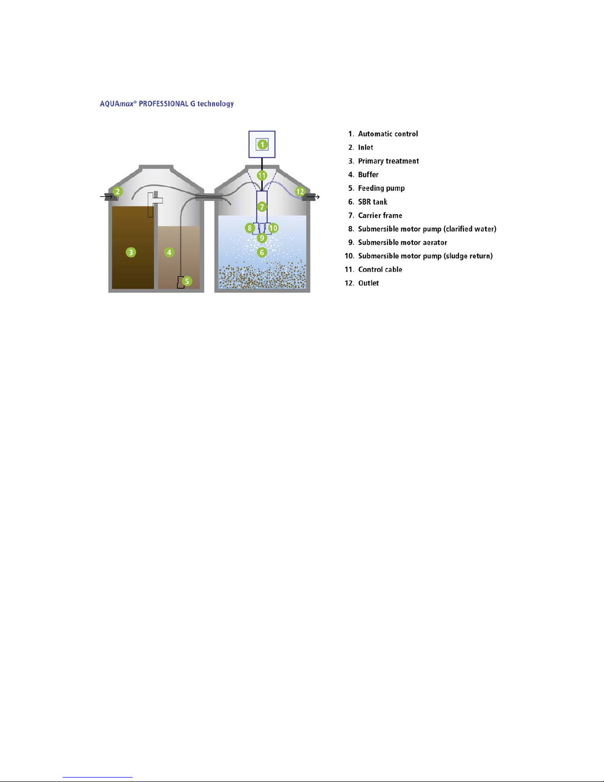
With the AQUAmax®one is concerned with a technical system which, together with a multi-
chamber, can be employed as small wastewater treatment plant for the aerobic biological
treatment of domestic and comparable wastewater of up to 8 m³/d from individual or several
buildings, collected using a separate system. Dimensioning, configuration and operation are to
take place in accordance with DIN EN 12566-3 and the approval of the German Institute for
Structural engineering (DIBt)!
With employment according to regulations no hazards whatsoever emanate from the plant. If the
AQUAmax®is used for other employment purposes without the express approval of ATB
Umwelttechnologien GmbH and/or if the following safety information is disregard, this can lead to
the hazarding or injury of persons and to malfunctions of or defects in the plant. In this case every
liability is excluded. Modifications to the plant or unauthorised conversions are not permitted.
The AQUAmax®and accessories are not intended to be used by persons (including children) with
limited physical, sensory or mental capabilities or without experience and/or knowledge, unless
they are supervised by a person responsible for their safety or receive from him/her instruction on
how to use the AQUAmax®and accessories. Children are to be supervised in order that they do
not play with these.
Before use the AQUAmax®is to be installed correctly and in agreement with the installation
instruction. Installation instructions, operation and maintenance instructions are to be read careful
before assembly and commissioning and the instructions contained therein must be followed
implicitly.
With assembly and installation, commissioning and operation as well as, if necessary,
decommissioning, the customary national standard specifications and provisions are to be
observed. All tasks may be carried out by trained and qualified specialists with an appropriate
certificate of qualification only. The operator of the plant is to be instructed by the service
technician.
With the connection of the control system the national applicable provisions as well as the details
on the specification plate are to be observed (mains voltage, frequency etc.). The equipment is to
be operated only on network configurations which include a protective earth (PE) conductor.
Attention is to be paid to correct phase connection (even with ready-to-plug
configurations)! Connection to the mains must be by means of separate fusing and earth leakage
circuit breaker (ELCB). Before commissioning the faultless function of the electrical safety
measures must be checked! Installation tasks are to be carried out by electrically skilled persons
only. With work on the equipment the mains plug must be disconnected. A separation or extension
of the leads is not permitted. The electrical connection data is to be taken from the specification
plate on the equipment.

Installation, operating and maintenance manual AQUAmax®PROFESSIONAL G
ATB WATER GmbH, Südstraße 2, D-32457 Porta Westfalica, www.atbwater.com /
Art.-Nr.: 9060 XXXX / Stand: 08.01.2019 / Seite 5 von 56
Do not operate any equipment which has a damaged connection/connecting lead or plug, which
exhibits a malfunction, has been dropped or is damaged in any way.
With all maintenance and repair tasks the plant is to be disconnected from the mains. The
AQUAmax®can be removed easily from the pit. If the plant has to be entered then this
(fundamentally) may take place only with the presence of a second person. Particular care is to be
taken. The applicable accident prevention regulations and the rules of technology are to be
observed.
The AQUAmax®submersible aerator feeds the required air to the wastewater through a rapidly
rotating propeller. Never operate in the vicinity of the aerator as long as the AQUAmax®is
connected to the mains supply. Danger of injury!
Only with the use of original spare parts or with spare parts authorised by ATB can correct function
be assured. Before commissioning all points of the operating instructions are to be checked again.
Keep these instructions available at all times!
Explanation of the warning notices used:
ATTENTION! Hazard due to electrical voltage!
Rotating parts. Danger of crushing or ingestion in the area of the submersible aerator!

Installation, operating and maintenance manual AQUAmax®PROFESSIONAL G
ATB WATER GmbH, Südstraße 2, D-32457 Porta Westfalica, www.atbwater.com /
Art.-Nr.: 9060 XXXX / Stand: 08.01.2019 / Seite 6 von 56
Scope of delivery
ATB goes to great lengths to ensure complete commissioning and product-matching
packaging for all equipment and parts supplied. Nevertheless, please check the
delivery for transport damage and completeness.
Technical data
(all units 230 V AC,
50 Hz):
Submersible aerator
AQUA 5: 0,56 kW / 2,5 A
Pumps
ATBLift 2: 0,3 kW / 1,3 A
FEKA 600: 1,0 kW / 4,3 A
More data for fault
diagnosis s.p. 49
AQUAmax®PROFESSIONAL
GZ 1-16
consisting of:
•1 carrier frame made of
PE/V2A for chain suspension
•1 submersible aerator AQUA 5
•1 submersible pump ATBlift 2
as clarified water pump
•1 submersible pump ATBlift 2
as excess sludge pump
•1 each float switch for HW,min
und HW,max
•15 m connection cable 7x1,5
mm² with special plug
AQUAmax®PROFESSIONAL
GZ 17-50
bestehend aus:
•1 carrier frame made of V2A for
chain suspension
•2 submersible aerators AQUA 5
•1 submersible pump ATBlift 2
as clarified water pump
•1 submersible pump ATBlift 2
as excess sludge pump
•1 each float switch for HW,min
und HW,max
•15 m connection cable 7x1,5
mm² with special plug
Accessories, loose:
•1 control system proControl©2,
230 V, for internal installation
•1 submersible pump FEKA 600
as charging pump with a
separate float switch as
protection against dry running
•1 sampling bottle made of PE
with harness
•5 m PVC-hose Ø 30 mm for
discharge
•10 m PVC-hose Ø 30 mm for
charging
•10 m PVC-hose Ø 30 mm for
sludge return
•1 set securing material
•1 information plate
Zubehör, lose:
•1 control system proControl©2,
230 V, for internal installation
•1 submersible pump FEKA 600
as charging pump with a
separate float switch as
protection against dry running
•1 sampling bottle made of PE
with harness
•5 m PVC-hose Ø 30 mm for
discharge
•10 m PVC-hose Ø 30 mm for
charging
•10 m PVC-hose Ø 30 mm for
sludge return
•1 set securing material
•1 information plate

Installation, operating and maintenance manual AQUAmax®PROFESSIONAL G
ATB WATER GmbH, Südstraße 2, D-32457 Porta Westfalica, www.atbwater.com /
Art.-Nr.: 9060 XXXX / Stand: 08.01.2019 / Seite 7 von 56
AQUAmax®PROFESSIONAL
GZB 1-16
consisting of:
•1 carrier frame made of
PE/V2A for chain suspension
•1 submersible pump ATBlift 2
as clarified water pump
•1 submersible pump ATBlift 2
as excess sludge pump
•1 each float switch for HW,min
und HW,max
•15 m connection cable 7x1,5
mm² with special plug
AQUAmax®PROFESSIONAL
GZB 17-32
consisting of:
•1 carrier frame made of
PE/V2A for chain suspension
•1 submersible pump ATBlift 2
as clarified water pump
•1 submersible pump ATBlift 2
as excess sludge pump
•1 each float switch for HW,min
und HW,max
•15 m connection cable 7x1,5
mm² with special plug
Accessories, loose:
•1 control system proControl©2,
230 V, for internal installation
•1 compressor JDK-S-120
•1 submersible pump FEKA 600
as charging pump with a
separate float switch as
protection against dry running
•1 sampling bottle made of PE
with harness
•5 m PVC-hose Ø 30 mm for
discharge
•10 m PVC-hose Ø 30 mm for
charging
•10 m PVC-hose Ø 30 mm for
sludge return
•2 tube aerators, 820 mm
•1 set securing material
•1 information plate
Accessories, loose:
•1 control system proControl©2,
230 V, for internal installation
•1 compressor JDK 200
•1 submersible pump FEKA 600
as charging pump with a
separate float switch as
protection against dry running
•1 sampling bottle made of PE
with harness
•5 m PVC-hose Ø 30 mm for
discharge
•10 m PVC-hose Ø 30 mm for
charging
•10 m PVC-hose Ø 30 mm for
sludge return
•3 tube aerators, 1070 mm
•1 set securing material
•1 information plate
Technical data: All units 230 V AC, 50 Hz
Compressor: JDK-S-120: 0,095 kW JDK 200: 0,18 kW
Pumps: ATBlift 2: 0,3 kW / 1,3 A FEKA 600: 1,0 kW / 4,3 A

Installation, operating and maintenance manual AQUAmax®PROFESSIONAL G
ATB WATER GmbH, Südstraße 2, D-32457 Porta Westfalica, www.atbwater.com /
Art.-Nr.: 9060 XXXX / Stand: 08.01.2019 / Seite 8 von 56
AQUAmax®PROFESSIONAL
GZB 33-50
consisting of:
•1 carrier frame made of PE/V2A
for chain suspension
•1 submersible pump ATBlift 2
as clarified water pump
•1 submersible pump ATBlift 2
as excess sludge pump
•1 each float switch for HW,min
und HW,max
•15 m connection cable 7x1,5
mm² with special plug
AQUAmax®PROFESSIONAL
GZB 51-75
consisting of:
•1 carrier frame made of V2A for
chain suspension
•1 submersible pump FEKA 600
as clarified water pump
•1 submersible pump FEKA 600
as excess sludge pump
•1 each float switch for HW,min
und HW,max
•15 m connection cable 7x1,5
mm² with special plug
Accessories, loose:
•1 control system proControl©2,
230 V, for internal installation
•2 compressors JDK 200
•1 submersible pump FEKA 600
as charging pump with a
separate float switch as
protection against dry running
•1 sampling bottle made of PE
with harness
•5 m PVC-hose Ø 30 mm for
discharge
•10 m PVC-hose Ø 30 mm for
charging
•10 m PVC-hose Ø 30 mm for
sludge return
•4 tube aerators, 107 mm
•1 set securing material
•1 information plate
Accessories, loose:
•1 control system proControl©2,
230 V, for internal installation
•2 compressors JDK 300
•1 submersible pump FEKA 600
as charging pump with a
separate float switch as
protection against dry running
•1 sampling bottle made of PE
with harness
•5 m PVC-hose Ø 30 mm for
discharge
•10 m PVC-hose Ø 30 mm for
charging
•10 m PVC-hose Ø 30 mm for
sludge return
•4 tube aerators, 1070 mm
•1 set securing material
•1 information plate
Technische Daten: Alle Aggregate 230 V AC
Verdichter: JDK 200: 0,18 kW JDK 300: 0,23 kW
Pumpen: ATBlift 2: 0,3 kW / 1,3 A FEKA 600: 1,0 kW / 4,3 A

Installation, operating and maintenance manual AQUAmax®PROFESSIONAL G
ATB WATER GmbH, Südstraße 2, D-32457 Porta Westfalica, www.atbwater.com /
Art.-Nr.: 9060 XXXX / Stand: 08.01.2019 / Seite 9 von 56

Installation, operating and maintenance manual AQUAmax®PROFESSIONAL G
ATB WATER GmbH, Südstraße 2, D-32457 Porta Westfalica, www.atbwater.com /
Art.-Nr.: 9060 XXXX / Stand: 08.01.2019 / Seite 10 von 56
Functional description
The sewage treatment plant operates according to the activated sludge principle in the back-up
process (SBR plant). The pollutants from the waste water are absorbed by floating microorganisms
(activated sludge) and converted into biomass.
A correspondingly large buffer volume is taken into account for buffering large quantities of waste
water that occur at peak times (e.g. hall operation of restaurants on weekends, commercial
operations).
The wastewater first enters the coarse trap/sludge storage tank and then into the buffer chamber.
At regular intervals, the waste water is pumped into the SBR chamber. When a maximum water
level is reached during revival, the pumping process is stopped. When a minimum water level is
reached in the buffer tank or after the preset charging time has elapsed, the pumping process is
terminated. Aeration occurs intermittently via a submersible motor aerator or a compressor and
diaphragm tube aerator. After approx. 6 hours the aeration phase ends and the settling phase
begins.
After a settling time of 1.5 hours, the treated wastewater is pumped off with the clear water pump.
The switch-off point of the pump is set via a float switch. If this minimum water level cannot be
reached due to a pump fault, an alarm is triggered. After approx. 8 hours the cycle ends with the
end of the clear water discharge and a new cycle begins.
The system reaches its full cleaning performance after a start-up time of approx. one month. In the
case of strong underload or temperatures below 12° C, it can also take longer for the biology to
develop completely. In this case it is recommended to inoculate with activated sludge to accelerate
this process.
The control system can be adapted to the particular case of need. During commissioning, the
system is set to the maximum number of persons connected. It is not necessary to change this
setting in the event of a short-time overload or underload.
Economic operation
If no wastewater flows into the system over a period of more than 4 hours, the system
automatically switches to energy-saving economic operation. The aeration time is reduced to such
an extent that the microorganisms have sufficient oxygen available. Under normal load, the system
switches back to the set operating mode.

Installation, operating and maintenance manual AQUAmax®PROFESSIONAL G
ATB WATER GmbH, Südstraße 2, D-32457 Porta Westfalica, www.atbwater.com /
Art.-Nr.: 9060 XXXX / Stand: 08.01.2019 / Seite 11 von 56
Sampling
Since the pumping process is of short duration, the purified water is collected in a suitable
container in the clear water tank (accessory: 1.5 l sampling bottle). The vessel is placed near the
cover and is therefore easily accessible from above. Alternatively, a vessel can also be placed in a
separate sampling chamber.
Installation and dimensioning
The systems can be individually dimensioned according to requirements.
Operation and maintenance
Small sewage treatment plants must be checked by the operator at certain intervals and should
maintained by a specialist for example twice a year. Both are important for the proper operation of
the systems. Depending on capacity utilization, the sludge is removed once a year or as required.
The machine technology can be pulled out through the system cover for maintenance purposes.
Application possibilities
The AQUAmax® PROFESSIONAL G is designed for the treatment of domestic wastewater. It is
particularly suitable for objects with irregular waste water production, e.g. hotels, restaurants,
butcher's shops, etc. For the treatment of waste water from e.g. apartments, other ATB sewage
treatment plants can be used.
The system must not be supplied with: commercial waste water (if not comparable with domestic
waste water), external water (e.g. drainage water), cooling water, discharge water from swimming
pools, rainwater.
Modular system
Phosphate removal and UV disinfection can be retrofitted.

Installation, operating and maintenance manual AQUAmax®PROFESSIONAL G
ATB WATER GmbH, Südstraße 2, D-32457 Porta Westfalica, www.atbwater.com /
Art.-Nr.: 9060 XXXX / Stand: 08.01.2019 / Seite 12 von 56
Services to be provided by the customer
•The tanks are offset at the appropriate height and watertight.
•A watertightnesss test has been carried out and concluded successfully. For this, the
installation instructions of the tank manufacturer are to be observed.
•All chambers of the plant are accessible to persons (clear openings of at least 600mm
diameter).
•A fully functioning aeration and ventilation of the plant must be assured. In normal cases this
takes place via the roof ventilation and a cover with ventilation openings in the (last) tank or
ventilation in the run-off pipe. The correct operation is to be documented and verified.
•The run-off pipeline is connected to the manhole and reaches ca. 15 cm into the shaft (do not
cut off at the manhole wall).
•Behind the wastewater treatment plant is located a further distributor, control or percolation
shaft. If this is not the case then a possibility for sampling is to be installed in the SBR tank.
•Should the buffer tank be divided into several chambers, then the partition wall must have
openings at the bottom.
•A 230 V power line is laid to the location of the control unit and is fused separately as follows:
B 16 A, and 25 A / 30 mA earth leakage circuit breaker (ELCB).
•Between the control unit and the wastewater treatment plant there are laid one (buffer and
SBR in one tank) or two (buffer and SBR in separate tanks) cable conduits (≥DN 100). There
may be no bends laid with a greater curvature angle than 30°! The cable conduits are to be
sealed odour-tight.
•Pull wires are included in the conduits. The maximum distance between control system and
AQUAmax®or buffer for the ready-to-plug variants is 35 m (for plants with compressor aeration
[GZB] 12 m).
•The tank is free of wastewater and cleaned.
•The AQUAmax®incl. accessories are on the construction site at the start of assembly.
•The inlet pipeline is connected to the primary settling stage. With retrofitting this, as a rule, has
been laid (if necessary please take note of the project sketch).
•The connection pipeline between primary settling stage, buffer and aeration stage is carried out
in DN 150. There may be no bend laid with a greater curvature angle than 45°.

Installation, operating and maintenance manual AQUAmax®PROFESSIONAL G
ATB WATER GmbH, Südstraße 2, D-32457 Porta Westfalica, www.atbwater.com /
Art.-Nr.: 9060 XXXX / Stand: 08.01.2019 / Seite 13 von 56
Float switches
Open float switch
= 0 in the status display
(Float switch has dropped)
Closed float switch
= 1 in the status display
(Float switch has floated up)
ATTENTION! Switching action is noticeable through a distinct "clack". The
switching situation changes relatively late (ca. +/- 50° related to the surface of the
water), so that an apparently floated up float switch can still be open or an
apparently dropped float switch can still be closed. Take note of status indicator!
Switch-OFF point (HW,min), all types
The switch-OFF point of the float switch, with all
types, is located at the height of the partition edge
between upper and lower part of the aerator
housing. The difference (= HW,min) between this
point and the tank sole may not be undercut.
Please take the values for HW,min from data sheets
or the technical clarification calculations.

Installation, operating and maintenance manual AQUAmax®PROFESSIONAL G
ATB WATER GmbH, Südstraße 2, D-32457 Porta Westfalica, www.atbwater.com /
Art.-Nr.: 9060 XXXX / Stand: 08.01.2019 / Seite 14 von 56
Tank preparation
A watertightness test must be carried out!
The openings between the primary
settling chambers must remain.
Openings and jointing between
primary settling stage and buffer or
SBR as well as between buffer and
SBR are to be closed and sealed.
It must be ensured that an
emergency overflow (> 40 cm²) exists
between buffer and SBR tanks.
Install T-piece
for the over-
flow between
(last) primary
settling
chamber and
buffer tank as
well as for the
runout.
The level
should lie at
one height.
For the cable
feed, plan one
(buffer and
SBR in one
tank) or two
(buffer and
SBR in
separate tanks)
openings (≥DN
100) per tank.

Installation, operating and maintenance manual AQUAmax®PROFESSIONAL G
ATB WATER GmbH, Südstraße 2, D-32457 Porta Westfalica, www.atbwater.com /
Art.-Nr.: 9060 XXXX / Stand: 08.01.2019 / Seite 15 von 56
Employment of the AQUAmax®
Please note with all connection work, that cables and hoses are long enough so
that the AQUAmax®can be removed from the plant without problem. Furthermore,
it is to be ensured that no cable is loaded under tension.
The stainless steel hooks provided are to be so fixed
to the tank cover, that the AQUAmax®is positioned
as far as possible in the middle of the tank. See to it
that the pipeline outlets for sludge and clarified water
point approximately in the direction of the
corresponding inlet and outlet pipelines (the outlets
have limited capability for rotation).
Now hang the AQUAmax®to the chains provided so
that the difference between the switch-OFF point of
float switch SW1 and the tank sole must correspond
at least with the value for HW,min from data sheet or
technical clarification calculation.
With this, the slope of the tensioned chain should not
be more than 45°.
Float switch SW2
Mount a further stainless steel hook above the SBR
tank.
Form a loop from the cable of the float switch for the
maximum water level in the SBR tank [HW,max / SW2]
with the aid of 2 cable straps. Following hanging up,
the difference between the switch-ON point of the
float switch and the switch-OFF point of the float
switch for HW,min [SW1] must at least correspond to
the difference between HW,min and HW,max from
technical clarification calculation/data sheets. Please
do not forget the float weight (mount ca. 10 cm in
front of the cable screw connection).
Please see that the switch-ON point of
SW2 in each case lies below the outlet!

Installation, operating and maintenance manual AQUAmax®PROFESSIONAL G
ATB WATER GmbH, Südstraße 2, D-32457 Porta Westfalica, www.atbwater.com /
Art.-Nr.: 9060 XXXX / Stand: 08.01.2019 / Seite 16 von 56
Employment of the charging pump
Mount a stainless steel hook above the buffer tank.
Prepare the charging pump with angled hose
nozzle, PVC hose (40 mm) and chain. The chain is
already secured to the pump handle using a
shackle.
The float switch is also attached to the handle
using two cable clips. The switch-OFF point should
lie approximately at the height of the centre of the
pump.
Please take care that the float switch moves freely
upwards and downwards and cannot jam.
For better handling hose, chain and cable are fixed
using cable straps.
Hang the pump ca. 5 cm above the sole in the
buffer tank. Here also take care that the pump is
not located to near the tank wall in order to ensure
the free movement of the float switch.
Secure the distributor box with the connection
cable to the cone.
Roll up the freely hanging cable and hang it up in
the OBO grip.
Pull the charging hose through the connecting pipe
in the SBR tank and secure the end to the cover
using a plastic clip.
Please ensure that you take care that
the free end of the charging hose
does not dip into the water in the SBR
tank or can submerge in order to
avoid a syphon effect (communicating
pipes)!

Installation, operating and maintenance manual AQUAmax®PROFESSIONAL G
ATB WATER GmbH, Südstraße 2, D-32457 Porta Westfalica, www.atbwater.com /
Art.-Nr.: 9060 XXXX / Stand: 08.01.2019 / Seite 17 von 56
Sampling bottle, clarified water and charging hoses
Up to 16 PT and from 51 PT red, from 17
to 50 PT blue connection cover!
Mount the sampling bottle on the cone so that the
sampling is easily achieved and the sample can be
easily removed. Screw the hose nozzle on to the
prepared clarified water hose (DN 25) to the threaded
connection on the pressure pipe of the clarified water
pump and cut it to length so that it can be pushed on to
the hose nozzle of the sampling bottle. With this take
note of the direction of flow of the sampling bottle!
Sampling bypass
A sampling bypass is included in the scope of delivery
for variants from 51 EW.
The sampling bottle represents a bottleneck, which
means, that the clear water discharge takes an
increasingly unfavourable period of time for larger
systems. This is prevented by the bypass, because a
part of the clear water flow is directed around the
sampling bottle.
Push the remaining hose far enough into the outlet so
that the clarified water cannot flow back (if necessary
provide an elbow on the outlet). Secure the hose
against slipping out using a pipe clip. If there is a non-
return valve installed in the clarified water hose or if the
sampling bottle is significantly higher than the outlet,
further measures can be necessary. In these cases
please contact our service department. A sufficient
freedom of movement for the removal of the bottle is to
be taken into account.
The pressureless outflow of the clarified water must be
guaranteed!
Screw the prepared hose for the excess sludge return
feed (DN 32) to the pressure pipe of the excess sludge
pump.
Pull the hose through the connecting pipe into the
coarse interceptor/sludge storage and secure the end
thereto the cover using a plastic clip.
Immersion in the wastewater of the coarse
interceptor/sludge storage is to be
avoided at all costs!
from
AQUAmax®
outlet
Bypass

Installation, operating and maintenance manual AQUAmax®PROFESSIONAL G
ATB WATER GmbH, Südstraße 2, D-32457 Porta Westfalica, www.atbwater.com /
Art.-Nr.: 9060 XXXX / Stand: 08.01.2019 / Seite 18 von 56
AQUAmax® with compressor and membrane tube diffusers
(AQUAmax® PROFESSIONAL GZB)
As an alternative to the submerged aerator, air can be blow in by one or two compressors and a
corresponding number of membrane tube diffusers (GZB versions).
The following figure shows an example of installation with two compressors
Using 25 mm hose compressor outputs are connected on preferably short distance to the air
adapter (not required if only one compressor is provided). This is connected in the tank to the air
allocator via 25 mm hose (empty pipe between compressor/adapter and tank). From here, the air is
transferred to the membrane diffusers via a 16 mm hose.
The air allocator is prepared for mounting in the tank above the water level or near the tank
opening.
The membrane diffusers are to be arranged on the bottom of the SBR so that an optimal aeration
is guaranteed. Due to their weight, they can be positioned without separate fixing.
Air adapter
Air allocator

Installation, operating and maintenance manual AQUAmax®PROFESSIONAL G
ATB WATER GmbH, Südstraße 2, D-32457 Porta Westfalica, www.atbwater.com /
Art.-Nr.: 9060 XXXX / Stand: 08.01.2019 / Seite 19 von 56
The AQUAmax® PROFESSIONAL GZB 1-16 is supplied with air via a 16 mm fabric hose, which is
laid directly from the compressor through the empty pipe into the tank. This is connected to the
membrane tube diffusers via a Y-piece.

Installation, operating and maintenance manual AQUAmax®PROFESSIONAL G
ATB WATER GmbH, Südstraße 2, D-32457 Porta Westfalica, www.atbwater.com /
Art.-Nr.: 9060 XXXX / Stand: 08.01.2019 / Seite 20 von 56
Cable connection and test run
Only for British standard plug system with earthing contact!
Take the adapter plug and the plug.
Press the plug into the adapter plug
The new plug is ready.
One-way assembly, to the unique
and for fixed connection. Without
destruction not solvable!
Pull the cable from the pit(s) through the empty
conduit(s) up to the proControl©2 control system
(pull wire). Cable lengths longer than 15 m are to
be considered when ordering.
Insert the special plug into the appropriate socket
of the proControl©2 control system and hand
tighten (see next pages).
Still do not connect the control system to the
mains.
The plant must now be filled be
filled with water at least up to the
switch-ON point of the lower float
switch in the SBR [SW1].
Following connection of the control system to the
mains it is activated and is in the program mode.
Please continue with commissioning and
functional check in accordance with the details
for the proControl©2 in the corresponding
chapter of this operating manual.
Table of contents
Other ATB Water Filtration System manuals
Popular Water Filtration System manuals by other brands

Schaffner
Schaffner FN 5060 Series General Mounting and Installation Guidelines

Kenmore
Kenmore Deluxe 625.384450 owner's manual

PTE
PTE ECOFLO STB-650B owner's manual

CALEFFI
CALEFFI 5709 Series manual

OSF
OSF WATERFRIEND exclusiv MRD-2 Installation and operating instructions

Davey
Davey Microlene UV68-CA Installation and operating instructions