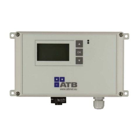
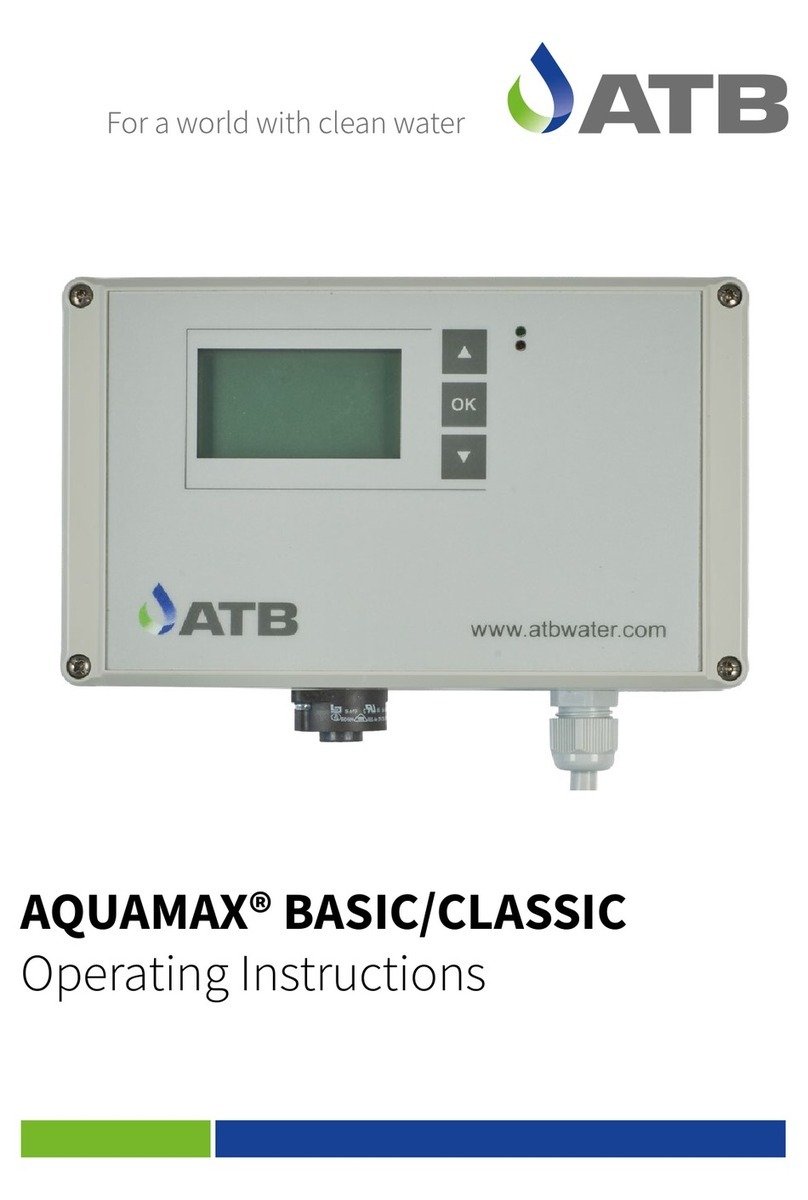
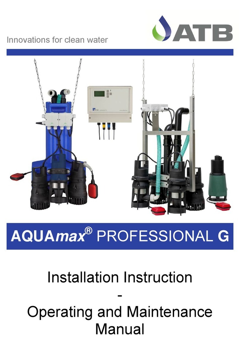
ATB AQUAmax CLASSIC series User manual

Innovations for clean water
AQUAmax®BASIC/CLASSIC
Installation Instructions


Installation instructions AQUAmax®BASIC/CLASSIC 1-75
ATB WATER GmbH, Südstraße 2, D-32457 Porta Westfalica, www.atbwater.com /
Art.-No.: 9060 0209 / Status: 17.01.2019 / Page 3 from 24
Contents
Page 4: General and safety information
Page 6: Scope of delivery
Page 9: Services to be provided by the customer
Page 10: Tank preparation / installation example
Page 12: Assembly drawing AQUAmax®CLASSIC Z, Switch-off point float switch
Page 13: Preparation of the AQUAmax®
Page 14: Installing of the AQUAmax®
Page 16: AQUAmax® with compressed aeration (ZB)
Page 18: Sampling bottle / Sampling bypass
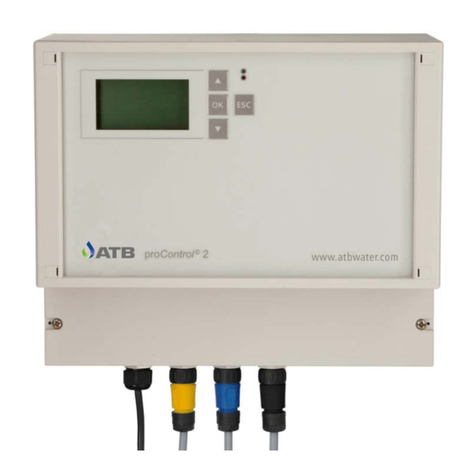
Page 19: The ATBcontrol© 3 control equipment
Page 21: Cable connection + test run
Page 22: Pre-commissioning check
Dear customer,
at this point we would like to thank you for the trust which you have shown with the purchase of this
product.
On the following pages you will find everything necessary about the installation, operation and the
maintenance requirements of your AQUAmax®small wastewater treatment plant.
Please observe that the careful installation of the wastewater treatment plant is very important for a
good treatment performance.

Installation instructions AQUAmax®BASIC/CLASSIC 1-75
ATB WATER GmbH, Südstraße 2, D-32457 Porta Westfalica, www.atbwater.com /
Art.-No.: 9060 0209 / Status: 17.01.2019 / Page 4 from 24
General and Safety Information
With the AQUAmax®one is concerned with a technical system which, in combination with a multi-
chamber tank, is employed as small wastewater treatment plant for the aerobic biological treatment
of domestic and comparable wastewater of up to 75 PE from single or several buildings.
Dimensioning, design and operation are to take place up to 50 PE in accordance with EN 12566-3.
With employment in accordance with regulations no hazards whatsoever emanate from the plant. If
the AQUAmax®is used for other purposes without the explicit approval of ATB WATER GmbH
and/or the following safety information is ignored, this can lead to the hazarding or injury of
persons and to malfunctions or defects in the plant. In this case any liability is excluded,
Modifications to the plant or unauthorized conversion is not permitted.
The AQUAmax®and accessories are not intended to be used by persons (including children) with
limited physical, sensory or mental capabilities or due to a lack of experience and/or knowledge,
unless they are supervised by or receive instruction from a person responsible for their safety, as
to how the AQUAmax®and accessories are to be used. Children are to be supervised in order to
ensure that they do not play with them.
Before use the AQUAmax®is to be installed correctly and in agreement with the installation
instructions. Installation instructions, operating and maintenance instructions are to be read
thoroughly and the instructions included therein are to be followed implicitly.
With assembly and installation, commissioning and operation as well as, if required,
decommissioning, national standard specifications and regulations are to be complied with. All
tasks may be carried out by trained and qualified specialists with appropriate certificate of technical
qualification. The operator is to be instructed by the fitter.
With the connection of the control system the national applicable regulations and the details on the
type plate are to be complied with (mains voltage, frequency etc.). The equipment is to be operated
on a network which includes a protective earth conductor (PE). Attention is to be paid to correct
phase connection (even with plug-in design)! The connection to the mains must take place by
means of separate fusing and residual current protective circuit breaker. Before commissioning,
the correct function of the electrical protective measures must be checked!
The installation work is to be carried out by qualified electricians only. With work on the equipment
fundamentally the mains plug is to be disconnected. A separation or extension of the cable is not
permitted. The electrical connection data is to be taken from the type plate on the equipment.
Operate no equipment which has a damaged connector/connection cable or plug, which indicates
a malfunction, has been dropped or has been damaged in any way.
With all maintenance and repair work the plant is to be disconnected from the mains. The
AQUAmax®can be removed easily from the tank. If the plant is to be climbed into, this may take
place only with the presence of a second person (this is fundamental!). Particular care is to be
taken. The applicable accident prevention regulations and rules of technology are to be complied
with.
In the versions with submersible aerator the AQUAmax®feeds the required air to the wastewater
through a rapidly rotating propeller. Never work in the vicinity of the aerator as long as the
AQUAmax®is connected with the mains. Danger of injury!
The correct function can only be guaranteed with the employment of original spare parts or spare
parts approved by ATB. Before commissioning, all points of the operating instructions are to be
checked. Keep these instructions readily to hand at all times!

Installation instructions AQUAmax®BASIC/CLASSIC 1-75
ATB WATER GmbH, Südstraße 2, D-32457 Porta Westfalica, www.atbwater.com /
Art.-No.: 9060 0209 / Status: 17.01.2019 / Page 5 from 24
Explanation of the warning notices used:
Attention! Danger due to electrical voltage!
Rotating parts. Danger of crushing and being drawn into the area of the submersible aerator!

Installation instructions AQUAmax®BASIC/CLASSIC 1-75
ATB WATER GmbH, Südstraße 2, D-32457 Porta Westfalica, www.atbwater.com /
Art.-No.: 9060 0209 / Status: 17.01.2019 / Page 6 from 24
Scope of Delivery
ATB goes to great lengths to achieve a complete consignment and product-specific
packaging of all equipment and parts supplied. Nevertheless, please check the delivery
for transportation damage and completeness.
AQUAmax®BASIC
consisting of:
•1 carrier frame made of
PE/V2A
•1 submers. aerator AQUA 5
•1 submersible pump ATBlift 2
as clarified water, excess
sludge and charging pump
•1 assembled pipeline set
made of PE incl. coarse filter
•1 integrated float switch
AQUAswitch©
•15 m connecting cable 7x1.5
mm² with special plug
•
AQUAmax® CLASSIC 1-16 Z
consisting of:
•1 carrier frame made of PE/
V2A for suspension on chains
•1 submers. aerator AQUA 5
•1 submersible pump ATBlift 2
as clarified water pump
•1 submersible pump ATBlift 2
as excess sludge and
charging pump
•1 integrated float switch
AQUAswitch©
•15 m connecting cable 7x1.5
mm² with special plug
AQUAmax®CLASSIC 17-50 Z
consisting of:
•1 carrier frame made of V2A
for suspension on chains
•2 submers. aerator AQUA 5
•1 submersible pump ATBlift 2
as clarified water pump
•1 submersible pump ATBlift 2
as excess sludge and
charging pump
•1 float switch
•15 m connecting cable 7x1.5
mm² with special plug
Accessories, loose:
•1 control unit ATBcontrol© 3,
230 V for internal attachment
•1 sampling bottle made of PE
with bracket
•3.5 m PVC hose Ø 25 mm for
cleared water
•1 set securing material
•1 indicator plate "Small
wastewater treatment plant
according to DIN"
Accessories, loose:
•1 control unit ATBcontrol© 3,
230 V for internal attachment
•1 sampling bottle made of PE
with bracket
•3.5 m PVC hose Ø 25 mm for
cleared water
•5.0 m PVC hose Ø 30 mm
with screw connection for
charging
•1 assembled pipeline set
made of PE incl. coarse filter
•1 set securing material
•1 indicator plate "Small
wastewater treatment plant
according to DIN"
Accessories, loose:
•1 control unit ATBcontrol© 3,
230 V for internal attachment
•1 sampling bottle made of PE
with bracket
•4,0 m PVC hose Ø 25 mm for
cleared water
•5,0 m PVC-hose Ø 40 mm
with screw connection for
charging
•1 assembled pipeline set
made of PE incl. coarse filter
•1 set securing material
•1 indicator plate "Small
wastewater treatment plant
according to DIN"
Technical Data:
Aerator AQUA 5: 230 VAC / 0,56 kW / 2,5 A. Pump ATBlift 2: 230 VAC / 0,3 kW / 1,3 A

Installation instructions AQUAmax®BASIC/CLASSIC 1-75
ATB WATER GmbH, Südstraße 2, D-32457 Porta Westfalica, www.atbwater.com /
Art.-No.: 9060 0209 / Status: 17.01.2019 / Page 7 from 24
AQUAmax®CLASSIC
1-16 ZB quarter chamber
consisting of:
•1 carrier frame made of PE/
V2A for suspension on
chains
•1 Compressor JDK-S-80
•1 submersible pump ATBlift
2 as clarified water pump
•1 submersible pump ATBlift
2 as excess sludge and
charging pump
•1 float switch
•15 m connecting cable 7x1.5
mm² with special plug
AQUAmax®CLASSIC
1-16 ZB half chamber
consisting of:
•1 carrier frame made of PE/
V2A for suspension on
chains
•1 Compressor JDK-S-100
•1 submersible pump ATBlift
2 as clarified water pump
•1 submersible pump ATBlift
2 as excess sludge and
charging pump
•1 float switch
•15 m connecting cable 7x1.5
mm² with special plug
AQUAmax®CLASSIC
1-16 ZB full chamber
(without dividing wall)
consisting of:
•1 carrier frame made of PE/
V2A for suspension on
chains
•1 Compressor JDK-S-120
•1 submersible pump ATBlift
2 as clarified water pump
•1 submersible pump ATBlift
2 as excess sludge and
charging pump
•1 float switch
•15 m connecting cable 7x1.5
mm² with special plug
Accessories, loose:
•1 control unit ATBcontrol© 3,
230 V, panel mounting
•1 sampling bottle made of
PE with bracket
•3.5 m PVC hose Ø 25 mm
for cleared water
•5.0 m PVC hose Ø 30 mm
with screw connection for
charging
•18 m hose Ø16 mm für
aeration
•1 membrane tube diffuser,
820 mm
•1 assembled pipeline set
made of PE incl. coarse filter
•1 set securing material
•1 indicator plate "Small
wastewater treatment plant
according to DIN"
Accessories, loose:
•1 control unit ATBcontrol© 3,
230 V, panel mounting
•1 sampling bottle made of
PE with bracket
•3.5 m PVC hose Ø 25 mm
for cleared water
•5.0 m PVC hose Ø 30 mm
with screw connection for
charging
•18 m hose Ø16 mm für
aeration
•2 membrane tube diffuser,
1070 mm
•1 assembled pipeline set
made of PE incl. coarse filter
•1 set securing material
•1 indicator plate "Small
wastewater treatment plant
according to DIN"
Technical Data: All 230 V AC
Compressor: JDK-S-80: 0,050 kW JDK-S-100: 0,075 kW JDK-S-120: 0,095 kW
Pumps: ATBlift 2: 0,3 kW / 1,3 A

Installation instructions AQUAmax®BASIC/CLASSIC 1-75
ATB WATER GmbH, Südstraße 2, D-32457 Porta Westfalica, www.atbwater.com /
Art.-No.: 9060 0209 / Status: 17.01.2019 / Page 8 from 24
AQUAmax®CLASSIC
17-32 ZB
consisting of:
•1 carrier frame made of PE/
V2A for suspension on
chains
•1 Compressor JDK 200
•1 submersible pump ATBlift
2 as clarified water pump
•1 submersible pump ATBlift
2 as excess sludge and
charging pump
•1 float switch
•15 m connecting cable 7x1.5
mm² with special plug
AQUAmax®CLASSIC
33-50 ZB
consisting of:
•1 carrier frame made of PE/
V2A for suspension on
chains
•2 Compressor JDK 200
•1 submersible pump ATBlift
2 as clarified water pump
•1 submersible pump ATBlift
2 as excess sludge and
charging pump
•1 float switch
•15 m connecting cable 7x1.5
mm² with special plug
AQUAmax®CLASSIC
51-75 ZB
consisting of:
•1 carrier frame made of V2A
for suspension on chains
•2 Compressor JDK 300
•1 submersible pump FEKA
600 as clarified water pump
•1 submersible pump FEKA
600 as excess sludge and
charging pump
•1 float switch
•15 m connecting cable 7x1.5
mm² with special plug
Accessories, loose:
•1 control unit ATBcontrol© 3,
230 V, panel mounting
•1 sampling bottle made of
PE with bracket
•5 m PVC hose Ø 25 mm for
cleared water
•5.0 m PVC hose Ø 40 mm
with screw connection for
charging
•18 m hose Ø16 mm für
aeration
•25 m hose Ø25 mm für
aeration
•3 membrane tube diffuser,
1070 mm
•1 assembled pipeline set
made of PE incl. coarse filter
•1 set securing material
•1 indicator plate "Small
wastewater treatment plant
according to DIN"
Accessories, loose:
•1 control unit ATBcontrol© 3,
230 V, panel mounting
•1 sampling bottle made of
PE with bracket
•5 m PVC hose Ø 25 mm for
cleared water
•5.0 m PVC hose Ø 40 mm
with screw connection for
charging
•18 m hose Ø16 mm für
aeration
•25 m hose Ø25 mm für
aeration
•4 membrane tube diffuser,
1070 mm
•1 assembled pipeline set
made of PE incl. coarse filter
•1 set securing material
•1 indicator plate "Small
wastewater treatment plant
according to DIN"
Accessories, loose:
•1 control unit ATBcontrol© 3,
230 V, panel mounting
•1 sampling bottle made of
PE with bracket
•5 m PVC hose Ø 30 mm for
cleared water
•5.0 m PVC hose Ø 50 mm
with screw connection for
charging
•18 m hose Ø16 mm für
aeration
•25 m hose Ø25 mm für
aeration
•4 membrane tube diffuser,
1070 mm
•1 assembled pipeline set
made of PE incl. coarse filter
•1 set securing material
•1 indicator plate "Small
wastewater treatment plant
according to DIN"
Technical Data: All 230 V AC
Compressor: JDK 200: 0,18 kW JDK 300: 0,23 kW
Pumps: ATBlift 2: 0,3 kW / 1,3 A FEKA 600: 1,0 kW / 4,3 A

Installation instructions AQUAmax®BASIC/CLASSIC 1-75
ATB WATER GmbH, Südstraße 2, D-32457 Porta Westfalica, www.atbwater.com /
Art.-No.: 9060 0209 / Status: 17.01.2019 / Page 9 from 24
Services to be Provided by the Customer
•The tanks are to be offset to the appropriate height and are to be watertight
•A watertightness test has been carried out and completed successfully. For this the installation
instructions of the tank manufacturer are to be complied with.
•All chambers of the plant are to be accessible for people (clear openings at least 60 cm
diameter).
•The cover of the tank with the aeration chamber must have ventilation openings. In addition a
ventilation facility at the outlet pipe plant is strongly recommended. The correct ventilation via
the roof is to be ensured.
•The outlet pipeline is connected to the manhole and protrudes ca. 15 cm into the manhole (do
not cut off at the manhole wall!).
•Behind the wastewater treatment plant there is a further distribution, monitoring or percolating
manhole. If this is not the case then a sampling possibility is to be installed in the SBR tank.
•A 230 V energy supply is to be laid and fused separately as follows: B 16 A, and residual
current circuit breaker 25 A / 30 mA.
•A cable pipe is to be laid between the control unit and the wastewater treatment plant. The
diameter should be at least 10 cm. No bends with a greater curvature angle than 30° are to be
laid. The cable pipe is to be sealed against odours.
•A draw wire is planned in the empty pipe. The maximum distance between control unit and
AQUAmax®for plug-in variants is 35 m, for plants with compressed aeration (ZB) 12 m.
•The tank is free of wastewater and cleaned.
•The AQUAmax®incl. accessories are on the construction site at the start of assembly.
•The partition wall between aeration stage and sludge storage is to be produced watertight and
provided with an emergency overflow (ca. 10 x 4 cm) in the upper area (single tank plant).
•The maximum difference between lower edge runoff and upper edge partition wall is 30 cm
(AQUAmax®BASIC and M configurations).
•The inlet pipeline is connected to the primary settling stage. With retrofitting this, as a rule, has
been relaid (Note drawing "Tank preparation" or project sketch).

Installation instructions AQUAmax®BASIC/CLASSIC 1-75
ATB WATER GmbH, Südstraße 2, D-32457 Porta Westfalica, www.atbwater.com /
Art.-No.: 9060 0209 / Status: 17.01.2019 / Page 10 from 24
Tank Preparation
AQUAmax®BASIC – New Plant
AQUAmax®BASIC - Retrofitting
Installation Example AQUAmax®BASIC
,
The diagram shows a typical installation of a 3-chamber
tank with installed AQUAmax®. With this, the suction pipe
of the AQUAmax®produces the connection to the last
chamber of the primary settling stage. Here the thick
matter is separated from the influent
Cover opening at least 60 cm diameter with ventilation
openings or separate ventilation pipe.
Emergency overflow, ca. 4 x 10 cm (H x W).
So far as the danger of a back-up exists in the inlet pipeline
and this is to be avoided, the lower edge of the emergency
opening is to be planned below the lower edge of the inlet.
Close openings in the partition wall. If necessary, reseal tank
joints.
Introduce empty pipe > DN 100 for cable at any desired
position.
Inlet and outlet must project ca. 15 cm into the plant.
Coarse interceptor
and slud
g
e store
Coarse interceptor
and slud
g
e store
SBR aeration
Inlet
Outlet
Cover opening at least 60 cm diameter with ventilation
openings or separate ventilation pipe.
Lay inlet into 2nd chamber and seal in.
Close openings in partition wall. If required, reseal tank joints.
Introduce empty pipe > DN 100 for cable at any desired
position.
Inlet and outlet must project ca. 15 cm into the plant (if
necessary, remove old partition walls) and/or mortise spigot
free.
An emergency overflow can be planned here (see above) in
order to use the half-chamber as additional buffer with power
or pump failure, before the water reaches the outlet.
Lower edge overflow must then lie below lower edge outlet but
above HW, max.
Coarse interceptor
and slud
g
e store
Inlet
Outlet
SBR aeration
CI and
slud
g
e store

Installation instructions AQUAmax®BASIC/CLASSIC 1-75
ATB WATER GmbH, Südstraße 2, D-32457 Porta Westfalica, www.atbwater.com /
Art.-No.: 9060 0209 / Status: 17.01.2019 / Page 11 from 24
Tank Preparation AQUAmax®CLASSIC Z – New Plant
Tank Preparation AQUAmax®CLASSIC Z - Retrofitting
Installation Example AQUAmax®CLASSIC Z
The diagram shows a typical installation of a 3-chamber tank with installed AQUAmax®.
With this, the suction pipe of the AQUAmax®produces the connection to the last chamber
of the primary settling stage. Here the thick matter is separated from the influent.
Coarse interceptor
and slud
g
e store
SBR aeration
Inlet Outlet
Cover opening at least 60
cm diameter. With
ventilation opening or
separate ventilation pipe
Introduce empty pipe ≥DN100
for cable at any desired posn
Introduce empty pipe ≥DN100
for cable at any desired posn
Inlet
Outlet
SBR aeration Coarse interceptor
and slud
g
e store
Cover opening at least 60 cm
diameter. With ventilation opening or
separate ventilation pipe
Old inlet, if
necessary, close
Relaying of
inlet pipe

Installation instructions AQUAmax®BASIC/CLASSIC 1-75
ATB WATER GmbH, Südstraße 2, D-32457 Porta Westfalica, www.atbwater.com /
Art.-No.: 9060 0209 / Status: 17.01.2019 / Page 12 from 24
Assembly Drawing AQUAmax® CLASSIC Z
Switch-off Point Float Switch (HW,min), all Types
The switch-off point of the float switch for all types is at the
height of the centre selvedge between upper and lower
part of the aerator housing. The difference (= HW,min)
between this point and the bottom of the tank should not be
exceeded.
The values for HW,min are to be taken from the data sheets
or the wastewater engineering calculations.
(see also marking on the side of the carrier frame)

Installation instructions AQUAmax®BASIC/CLASSIC 1-75
ATB WATER GmbH, Südstraße 2, D-32457 Porta Westfalica, www.atbwater.com /
Art.-No.: 9060 0209 / Status: 17.01.2019 / Page 13 from 24
Preparation of the AQUAmax®
AQUAmax®BASIC
Before locating the AQUAmax®BASIC in the cesspit, check the mounting bracket for the correct,
and for the number of connected inhabitants, matching position. The lower position of the mounting
bracket is provided for 4-8, the upper for 9-16 PT (see also the stamp on the plastic bodywork). If
required, loosen the securing screw and relocate the mounting bracket.
AQUAmax®CLASSIC Z / ZB
Secure the stainless steel hooks supplied in such a way on the tank cover that the
AQUAmax®is positioned as far as possible centrally in the tank. See to it that the pipeline
outlets for sludge and clarified water are approximately pointing in the direction of the
appropriate inflow and outflow pipelines. Connect the outlet hose (25 mm) with the
AQUAmax®by means of a coupler connection.
Now suspend the AQUAmax®on the chains supplied so that the float switch-off point agrees with
HW,min. The slope of the tensioned chain should not be more than 45° to the vertical.

Installation instructions AQUAmax®BASIC/CLASSIC 1-75
ATB WATER GmbH, Südstraße 2, D-32457 Porta Westfalica, www.atbwater.com /
Art.-No.: 9060 0209 / Status: 17.01.2019 / Page 14 from 24
Installing AQUAmax®
A communicating tube forms the connection to the primary chamber. This system
works only with absolute tightness! Please ensure that cables and hoses are long
enough so that the AQUAmax® can be easily take out of the tank. Cables must not be
subjected to tensile stress.
AQUAmax®BASIC, CLASSIC M
AQUAmax®BASIC, CLASSIC M are placed centrally on the partition wall. The immersion pipe
must dip into the 2nd primary settling chamber (not the inlet chamber). With single-chamber primary
settling an additional protective pipe or a scum board is to be provided for the immersion pipe.
Connect the outlet hose with the AQUAmax®by means of a coupler connection.
AQUAmax®CLASSIC Z / ZB
With the AQUAmax®CLASSIC Z push the 30 respectively 40 mm PVC hose through the
connecting pipe to the primary settling stage and, using the coupler connection screw on to the
sludge pipe. Lay the hose in such a way that this does not sag. Secure the sludge pipe using the
enclosed pipe clips such theat the inlet opening is at the height of HW,min. Connect PVC hose and
immersion pipe by means of the enclosed hose clips. If required, the immersion pipe must be
secured against the ingress of thick matter floating sludge (see below).

Installation instructions AQUAmax®BASIC/CLASSIC 1-75
ATB WATER GmbH, Südstraße 2, D-32457 Porta Westfalica, www.atbwater.com /
Art.-No.: 9060 0209 / Status: 17.01.2019 / Page 15 from 24

Installation instructions AQUAmax®BASIC/CLASSIC 1-75
ATB WATER GmbH, Südstraße 2, D-32457 Porta Westfalica, www.atbwater.com /
Art.-No.: 9060 0209 / Status: 17.01.2019 / Page 16 from 24
AQUAmax®with compressed aeration (AQUAmax®ZB)
As an alternative to the submerged aerator, the CLASSIC Z versions can be supplied with air via
one or two compressors and a corresponding number of membrane tube aerators.
An exemplary illustration of the installation with two compressors can be seen in the following
figure.
The compressor outputs are connected to the air adapter using a 25 mm fabric hose in the shortest
possible way (not required if only one compressor is provided). This is also connected to the air
distributor Multi and through the empty pipe in the tank with a 25 mm fabric hose. From here, the
air is routed to the membrane diffusers via a 16 mm fabric hose.
The air distributor is prepared for mounting in the tank above the water level or near the tank
opening.
The membrane aerators are to be placed on the bottom of the biology so that an optimal aeration
pattern is guaranteed. Because of their weight, they can be positioned without separate
attachment.
At the AQUAmax® 1-16 ZB, the air is supplied via a 16 mm fabric hose, which is laid directly from
the compressor through the empty tube into the tank. This is connected directly to the membrane
air diffuser in the case of the quarter-chamber version or via a Y-piece in the case of the half-
chamber version (see next page).
Luftadapter
Luft
verteil
er

Installation instructions AQUAmax®BASIC/CLASSIC 1-75
ATB WATER GmbH, Südstraße 2, D-32457 Porta Westfalica, www.atbwater.com /
Art.-No.: 9060 0209 / Status: 17.01.2019 / Page 17 from 24
AQUAmax®CLASSIC 1-16 ZB (quarter chamber)
AQUAmax®CLASSIC 1-16 ZB
(half- and full chamber)

Installation instructions AQUAmax®BASIC/CLASSIC 1-75
ATB WATER GmbH, Südstraße 2, D-32457 Porta Westfalica, www.atbwater.com /
Art.-No.: 9060 0209 / Status: 17.01.2019 / Page 18 from 24
Sampling bottle
Up to 16 PE and over 51 PE red connection cover, 17-50 PE blue connection cover!
The sampling bottle is attached to the cone of the sewage treatment plant with a holder. The holder
should be provided where is no obstacle when removing the AQUAmax®.
Cut the outlet hose to length and place it on the inlet nozzle of the sampling bottle (note the
marking/flow direction!).
Put the remaining hose on the outlet spout and push it into the outlet so far that the clear water
cannot flow back. Secure the hose with a pipe clamp to prevent it from slipping out. If a non-return
flap is installed in the clear water hose or if the sampling bottle is mounted significantly higher than
the outlet, further action may be necessary. In these cases, please contact our service department.
Sufficient space must be ensured for removing the bottle.
Sampling-Bypass
For variants over 50 PE, a sampling bypass is included in the scope of delivery.
The sampling bottle represents a bottleneck which, in the case of larger systems, means that the
clear water discharge takes up an increasingly unfavourable amount of time. This is prevented by
the bypass, because a part of the clear water flow is routed around the sampling bottle.
Observe flow
direction!
From
AQUAmax®
Outlet
Bypass

Installation instructions AQUAmax®BASIC/CLASSIC 1-75
ATB WATER GmbH, Südstraße 2, D-32457 Porta Westfalica, www.atbwater.com /
Art.-No.: 9060 0209 / Status: 17.01.2019 / Page 19 from 24
Control unit ATBcontrol© 3
Control unit for the activation of small wastewater treatment plants of the types AQUAmax®BASIC
/ CLASSIC and AQUAPRIMO
General and safety information
With intended employment of the equipment no hazards whatsoever emanate from the unit.
National applicable regulations and technical data are to be observed.
Should the ATBcontrol© 3 be used for other purposes without the express approval of ATB WATER
GmbH and/or if the following safety information is disregarded, this can lead to malfunction of or
defects in the plant. In this case any liability is ruled out.
Modifications to the unit are not permitted and lead to the loss of all claims under warranty.
Do not operate any unit which indicates malfunctions, has been dropped or is damaged in any
way.
Features
•Microprocessor controlled
•USB connection for data readout and input
•Splash water protected. Conditionally suitable for outside areas (IP54)
•Wall mounting
•Voltage failure detection system (UVS®)
•Potential-free contact for an additional alarm facility
•Simple and rapid operation
•Times for all parameters completely pre-programmed
•Automatic run-in phase with suppression of excess sludge removal
•Parameter settings freely selectable
•Alarm interval
•Alarm volume adjustable
•Deployable for AQUAmax®BASIC / CLASSIC and AQUAPRIMO
•Plug-in
•Winter operation and sludge removal mode for the reduction of the aeration times

Installation instructions AQUAmax®BASIC/CLASSIC 1-75
ATB WATER GmbH, Südstraße 2, D-32457 Porta Westfalica, www.atbwater.com /
Art.-No.: 9060 0209 / Status: 17.01.2019 / Page 20 from 24
Assembly
Using the mounting materials provided secure the ATBcontrol© 3 to the casing provided for this and
to a suitable, as far as possible, weather-protected position.
The ATBcontrol© 3 is supplied as plug-in variant. Cabling on site is dispensed with.
For the AQUAmax® ZB with compressed aeration, the control unit is already mounted on a
mounting plate. This can be mounted directly on the wall or in an outdoor cabinet.
Next to the control unit there is a distribution box on the mounting plate to which the AQUAmax® is
connected, as well as the sockets for the control unit (and mains cable) and the compressor(s).
AQUAmax®ZB mounting plate for one compressor
(1-32 PE)
AQUAmax®ZB mounting plate for two compressors
(>32 PE)
All tasks, which nevertheless require an opening of the control unit, are to be carried out by
a qualified electrician!
ATTENTION! Before opening the ATBcontrol© 3 and/or the connection box it/they
must be disconnected from the mains supply. Work on opened units may be
carried out exclusively by qualified electricians! Pay attention to phase-correct
connection (even with plug-in design)!
As you are concerned with an electrical plant with submerged motor units, a
separate B16 fuse and a (separate) upstream 30 mA ELCB (earth leakage circuit
breaker) is absolutely essential!
Attention is to be paid to correct laying of the protective earth conductor up to the
earthing of the building.
Compressor 1/2
Mains
AQUAmax
®
Mains
AQUAmax
®
Compressor
This manual suits for next models
9
Table of contents
Other ATB Water Filtration System manuals
Popular Water Filtration System manuals by other brands

Cuisinart
Cuisinart CleanWater WCH-1500 Instruction booklet

Anchor
Anchor AF-6001 Quick setup guide

Kessel
Kessel SE M NS 2 Installation, operating and maintenance instructions

SMC Networks
SMC Networks FGD series operating manual

Pentair
Pentair CLEAN AND CLEAR PLUS Cleaning guide

AICKSN
AICKSN AICKSN-RO-200 quick start guide