Term
DCE
DTE
TxON, RxON
TxRTS, RxON
TxDTR/RTS, RxDSR/ON
Meaning
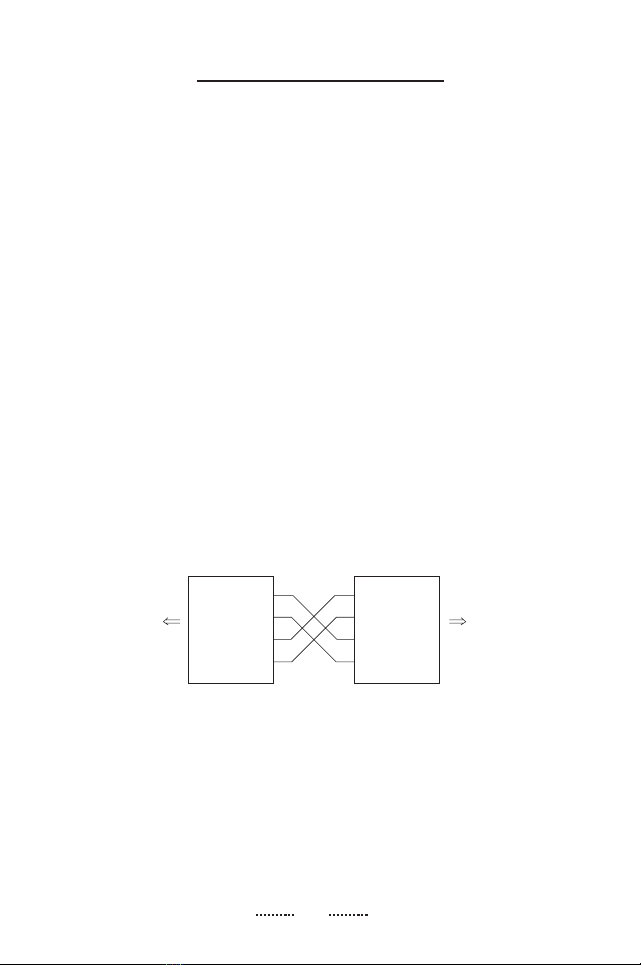
DCE means Data Communication Equipment; if the
IC-485SN is going to be plugged into a DTE
device, the IC-485SN must be set to DCE.
DTE means Data Terminal Equipment; if the IC-
485SN is going to be plugged into a DCE device,
the IC-485SN must be set to DTE.
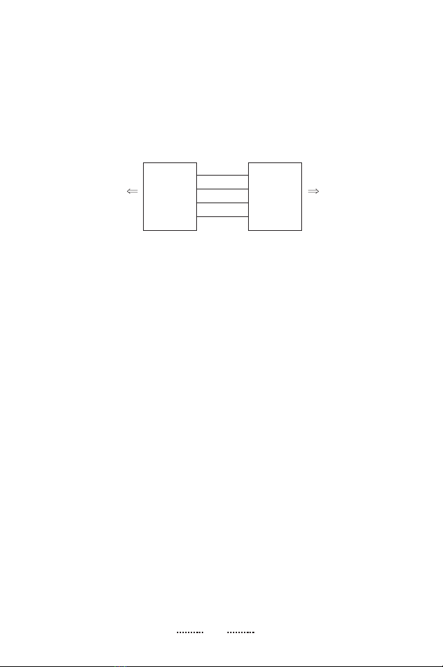
This setting is used in Point-to-Point operations, in
which the unit is always in Transmitting and
Receiving mode. (See P.10 Schematic)
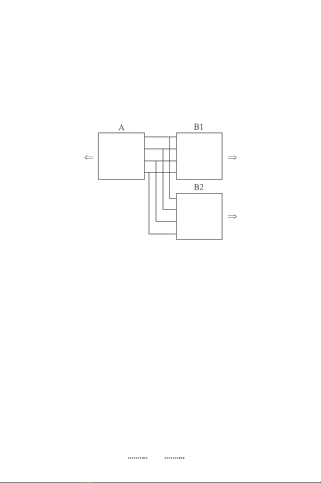
This setting is used in Multidrop operations, in which
the unit is always in receiving mode and it is in
transmitting mode only when the RTS signal is high.
(See P.11 Schematic)
This setting is used in Multidrop Half Duplex
operations to monitor the RS-485 line signals.
Receiving mode is always ON. DSR is used to check
If the line is busy. If not busy, the RTS signal is set
high, allowing data transmission. Prior to
transmission a DTR signal is sent to keep the other
devices from transmitting.
(See P.11 Schematic)
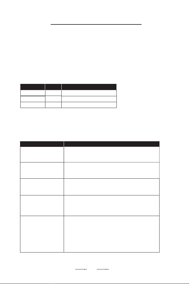
Position
1
2
3
SW1
DCE
DTE
SW2
TxON, RxON
TxRTS, RxON
TxDTR/RTS, RxDSR/ON
3
Switch Configuration
The IC-485SN is configured by setting two slide
switches.SW1isusedtoselecttheIC-485SN's
Device Mode; SW2 is used to select the IC-485SN's
Transmitting and Receiving Mode, as shown in the
table below:
An explanation of the SW1 and SW2 terms is given
in the table below: