Atlantis P140 User manual

1
FEEL THE STRENGTH
OWNER’S
MANUAL
2020

2
Please note: The information in this manual pertains to models produced January 1st, 2020 and later.
Do not apply any recommendation or instruction found in this manual to units produced before the
aforementioned date without consulting our Atlantis service department first.
FEEL THE STRENGTH
TABLE
OF
CONTENTS
03 ASSEMBLY INSTRUCTIONS
07 SAFETY INSTRUCTIONS
08 PREVENTIVE MAINTENANCE
AND INSPECTION
13 REPLACING PARTS
15 TROUBLE SHOOTING
16 WARRANTY POLICY
19 CONTACT INFORMATION
This manual will provide you and your staff with valuable information
regarding the operation and maintenance of your Atlantis equipment so that
your members enjoy years of safe and exhilarating strength training pleasure.
USING THIS MANUAL
All Atlantis units can be identified by a code that features 1 or 2 letters, and 3
numbers. For example, the code P140 identifies the selectorized Seated Chest
Press. All weight stack units (selectorized units) and plate-loaded units feature
instructional placards that have their product codes printed on them as well.
All other units may be identified by the product code found in your catalog, by
the serial number (silver sticker near the bottom of the frame with 5 numbers)
or by describing the unit’s function and features to a representative.
Placards
Serial number
P140 (01-0142)

3
ASSEMBLY INSTRUCTIONS
9/16” (14 mm)
wrench or
crescent wrench
The tools listed above are required to install weight stacks, remove pads and disassemble any
Atlantis bolt combination. Bolts need to be removed with impact driver or ratchet fitted with 9/16”
(14 mm) socket and 9/16” (14 mm) wrench or crescent wrench. Be sure to re-install all bolts and
washer’s combinations in the same order they were removed. Atlantis strongly recommends at least
two people perform the following procedures for safety and comfort.
WARNING: Please note that shipping units (even over very short distances) can
loosen the tightest of bolts. It is therefore extremely important that all bolts be
carefully tightened before any equipment is used and on a regular basis thereafter.
The required tools for assembly are:
1Assembly instructions
Impact driver or ratchet
socket wrench fitted with
9/16” (14 mm) socket

4
These units are typically shipped fully assembled and ready to use. In some instances, units will be
“compressed” to save space for shipping and are assembled with shortened beams. It is important to
note that although the shortened beams are discarded after shipping, the hardware (bolts) must be
reused. If a pad has been removed for installation purposes, be careful not to over tighten the T-nut
bolts when reinstalling the pad on the unit. In order to do so, tighten the bolts by hand before using a
ratchet or impact driver.
Weight stack units are typically shipped fully assembled apart from
their weight stacks which are packed in boxes. It is important to follow
the diagram labeled on each machine to make sure that the proper
plates are installed.
Please note that the following units do not feature the 5 lb (2.3 kg) add-
on weights described within the installation instructions:
• C113 Total Hip
• M118 Standing Calf
• M318 Incline Calf Raise
• NM205 Dynamic Functional Training System
Racks, benches and plate-loaded units
Weight stack units
ASSEMBLY INSTRUCTIONS
1
5 LB (2.3 KG) ADDON WEIGHTS

5
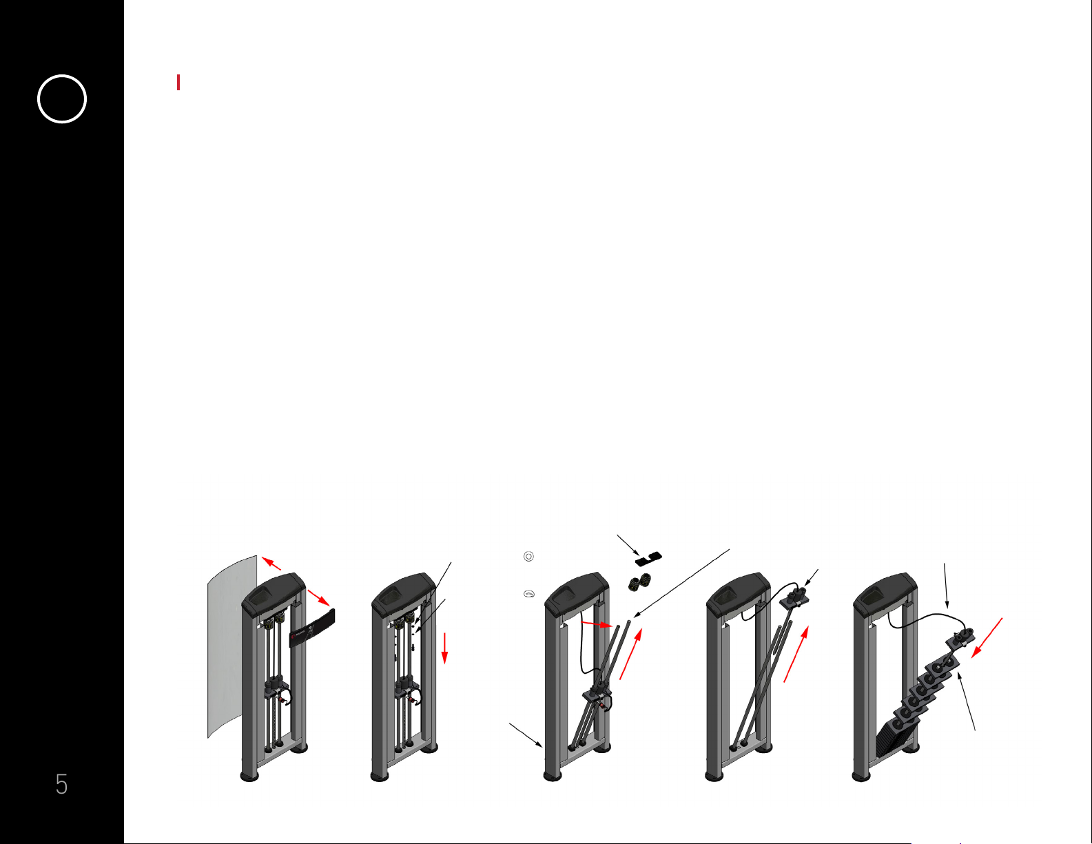
1) First remove the top panel (A)
from the top of the machine.
Next, manually slide out the unit’s
protective shroud (B) from its tracks
on the sides of the frame and put it
aside.
2) Lower the add-on weights so that
they are resting on the top plate. This
will expose the two silver cylindrical
bolts and black plastic bracket (C)
holding the chromed guide rods (D)
in place. Loosen and remove both
cylindrical bolts and the black plastic
bracket.
On most stations, you will find special
“split” washers (also called lock
washers) and “flat” washers between
the cylindrical bolt and the bracket
that are very important. They keep the
bolts from vibrating loose over time.
Securely install the “flat” washer
under the plastic bracket (C) and the
“split” washer between the cylindrical
bolt and the “flat” washer. On other
stations, you will find regular nut and
bolt assemblies that do not require
these washers. Carefully let the guide
rods lean to whichever side of the unit
is easiest to work on. The rods will
lean about 60 degrees and sit safely
in place on an angle.
ASSEMBLY INSTRUCTIONS
1Weight stack units: Installing the weight stack
3) Remove the two add-on weights.
4) Grasp the top plate (hanging on either
a belt or a cable) and slide it off the
top of the guide rods. Let the top
plate (E) hang on the belt or cable and
place it to one side.
5) Slide all the weight plates (F) onto the
guide rods one at a time as per the
diagram. Slide the hanging top plate
back onto the guide rods to complete
the weight stack without twisting the
belt or cable.
(F) WEIGHT PLATES
CABLE OR BELT
(E) TOP PLATE
(D) DOUBLE CHROMED RODS
(C) PLASTIC BRACKET
FLAT WASHERS
SPLIT WASHERS
(B) SHROUD
1 2 3 4 5
(A) FRONT PANEL

6
6) Slide back the two add-on weights (G).
7) Push the rods back into place. Place
the black plastic bracket into position
and secure it to the frame with the
cylindrical bolts. Replace the “split” and
“flat” washers. (See p. 5, #2)
8) Slide each add-on weight up the
guide rod and twist it into the stored
position on the cylindrical bolt.
9) Put the weight sticker on each plate
as per diagram. NOTE: Fronts of
plates should be wiped with rubbing
alcohol before the stickers are
applied to remove surface oils and to
ensure proper adhesion.
ASSEMBLY INSTRUCTIONS
1Weight stack units: Installing the weight stack
10) Put the shroud and front panel back.
WEIGHT STICKERS
(G) ADDON WEIGHT 5 LB (2.3 KG)
6 7 8 9 10

7
SAFETY INSTRUCTIONS
Your Atlantis equipment has been carefully designed to be used safely under normal operating
conditions. However, the practice of educating individuals who encounter your equipment and
properly inspecting and maintaining units on a regular basis (see
(3) Preventive Maintenance
in this
manual) will greatly enhance the safety level of your facility. Anyone who comes into contact with the
equipment must be familiar with its operation and the potential hazards associated with improper
use or maintenance.
Atlantis recommends that all equipment be secured to the floor, to a solid, level surface to
avoid tipping over or rocking. This must be performed by a licensed contractor.
2Safety instructions
• Read all warnings and obtain
instructions before using Atlantis
equipment. Use each unit for its
intended exercise(s) only. Do not
modify a unit in any way.
• Ensure that all users obtain a medical
exam and receive proper instructions
before using Atlantis equipment.
• Users and bystanders must keep all
body parts and clothing away from
moving parts during use.
• Follow the suggested inspection
schedule found in this manual. Do not
allow anyone to use a unit if it appears
to be damaged. Do not attempt to fix a
broken or jammed machine if you are
not qualified to do so.
• Use only the weight selector pin
provided by the manufacturer. Do not
improvise. If in doubt, consult an Atlantis
representative prior to any intervention.
• Do not use dumbbells, weight plates or
any other means to add resistance to
weight stack (selectorized) units.
• Do not exceed personal strength levels
or overload equipment.
• Keep children away from equipment and
supervise teenagers.
• Do not remove any labels from Atlantis
equipment. Replace damaged labels
immediately.

8
PREVENTIVE MAINTENANCE
AND INSPECTION
Every step in the design and production phase of manufacturing is taken to ensure that your Atlantis
equipment will operate safely and efficiently under normal conditions and in commercial settings
for prolonged periods of time. However, as with any machinery with moving parts, your equipment is
subject to wear and must be maintained and inspected on a regular basis. Failure to do so will cause
unnecessary damage or premature wear on a unit’s components, and in turn pose serious safety
hazards to users.
Every weight stack and linear bearing needs to be treated specifically by following the
recommendations provided in this manual. If in doubt, consult an Atlantis representative prior to any
intervention.
Atlantis will not be held responsible for any personal injury or damages resulting from improper
maintenance, misuse or negligence.
3Preventive maintenance and inspection
• Clean upholstery with any upholstery safe sanitizing spray using a
soft damp cloth (clean, sweat-free upholstery lasts up to 40% longer).
For especially persistent stains, apply rubbing alcohol liberally with a
soft cloth and wipe dry with another cloth after rinsing area with clean
water.
• Recommended upholstery cleaning products:
Primary: Formula 409 All-Purpose Cleaner
Secondary:
— Lysol Clean and Fresh Multi-Surface Cleaner (Reckitt Benckiser)
— Lestoil Heavy Duty Cleaner (Clorox)
— Mr. Clean / Flash Clean and Shine (Procter and Gamble)
— Eco Touch All Purpose Premium Care
Maintenance and inspection schedule: Daily maintenance
Do not use abrasive powder, steel wool, or industrial strength
or solvent cleaners. The use of upholstery “conditioners” or
“protectants” is not recommended and should be avoided on
all vinyl coated fabrics. Also note that repeated use of any
disinfectants and cleaning agents will degrade coated fabrics
upholstery to some extent. For high traffic/wear applications that
require repeated cleaning and disinfecting, it is recommended to
use coated fabric products with PreFixx®Protective Finish.

9
PREVENTIVE MAINTENANCE
AND INSPECTION
3
• Carefully inspect pull pins, snap locks, weight stack
selector pins and all pivoting connecting parts. Replace
at first sign of wear.
• Inspect cables thoroughly over their entire length and
at each insertion point and replace immediately if
damaged. When changing a cable, note the replacement
date for your records (see
(4) Replacing Parts
section in
this manual).
• Inspect cables thoroughly over their entire length and
at each insertion point and replace immediately if
damaged. When changing a cable, note the replacement
date for your records (see
(4) Replacing Parts
section in
this manual).
• Inspect belts thoroughly over their entire length
and at each insertion point. If a belt shows signs of
delaminating, cracking or wear that has reduced its
original width or thickness, it should be replaced
immediately. All insertion point hardware should also be
carefully inspected for signs of wear. When changing a
belt, note the replacement date for your records (see
(4)
Replacing Parts
section in this manual).
Maintenance and inspection schedule: Weekly maintenance
ASSEMBLY WITH ACCESSORY HOOK
ALLEN KEY 5/32
ALLEN KEY 7/32
KEY 9/16
ALLEN KEY 5/32

10
PREVENTIVE MAINTENANCE
AND INSPECTION
3
• Clean weight stack guide rods with dry towel and lubricate
with TFL- 50 wet lube. Do not use silicone or any other
type of lubricant. Wipe guide rods clean and apply
lubricant from the top down, allowing slight excess to
run down guide rods and into the weight stack. If using
a spray can or bottle, be sure to shield the rest of the
unit from over spray as product can stain. Occasionally,
have an assistant lift the weight stack at different weight
values (exercise extreme caution when performing this
maneuver), and apply lubricant to the portions of the
guide rods that are usually hidden by the weight stack if
they seem dry. Weight stack guide rods should be clean
and have a light layer of lubricant on them for optimal
performance. Failing to wipe guide rods clean first will
lead to unwanted resistance and premature wear on
bushings.
• Clean linear bearing guide rods on Smith machines (E155)
with a dry towel and lubricate with multipurpose grease.
Do not use silicone or any other type of lubricant. Atlantis
recommends the spray can format of Super Lube®, an
excellent multipurpose Teflon-based lubricant.
• Lightly grease stainless steel seat shafts and backrests,
accessory bars, and pivoting handles with multipurpose
grease or Super Lube®. Never lubricate the piston shaft of
a hydraulic or gas spring shock.
• Inspect all labels. Replace any damaged or missing labels.
• Tighten all nuts and bolts.
Maintenance and inspection schedule: Weekly maintenance
ASSEMBLY WITH TOP PLATE BRACKET
CABLE
ALLEN KEY 5/32

11
ATLANS'
26-05-2020
DIAGRAM 2H
LOOSE CABLE
www.atlantisstrength.com
PREVENTIVE MAINTENANCE
AND INSPECTION
3
• Check cables for correct tension on crossovers, adjustable pulleys and functional training
systems (NM200/NM205). If the cable is loose, use the cable adjustment screw attached to the
housing of the pulley assembly (see figures below). The cable will tighten as the screw goes down.
• Clean frames and inside of weight stack shrouds with a solution of Simple Green®All-Purpose
Cleaner (an environmentally-friendly, non-toxic, and biodegradable cleaner). Dirt and dust are
your machine’s worst enemy! Keeping units clean is an important part of their performance and
durability.
Maintenance and inspection schedule: Monthly maintenance
TURN DOWNWARD TO TIGHTEN
LOOSE
CABLE

12
PREVENTIVE MAINTENANCE
AND INSPECTION
3
• Clean frames as indicated above and polish with automotive grade wax to protect finish from
surface rust and corrosion. This recommendation is especially pertinent for facilities located
in high-humidity regions.
To order TFL-50 in Canada: contact Atlantis by email at service@atlantisstrength.com or from
8:30am - 4:30pm Eastern Standard Time (UTC-5) at 1-877-454-2285, ext. 239.
To order TFL-50 in the United States or internationally: contact TFL International from
To order Super Lube in Canada: contact Atlantis by email at service@atlantisstrength.com or from
8:30am - 4:30pm Eastern Standard Time (UTC-5) at 1-877-454-2285, ext. 239.
Maintenance and inspection schedule: Yearly maintenance
Ordering recommended lubricants

13
REPLACING PARTS
Cables come in two different sizes: 1/8” (3 mm) and 3/16” (4.8 mm). The 1/8” (3 mm) cable is more
flexible and is used for units with a total weight stack of up to 200 lb (91 kg). The 3/16” (4.8 mm)
cable is less malleable and recommended for units with a weight stack over 200 lb (91 kg).
If unsure of the cable size to use, please contact a customer service representative.
NOTE: The A201 and A301 are the only machines that use a Kevlar belt instead of a cable.
4Cables
www.atlantisstrength.com
ASSEMBLAGE POUR COURROIE
DIAGRAMME 2-F
2020-05-21
BELT: A201 BELT: A301
BELT BELT
METAL RING
BOLT (2X)
LOCK WASHER (2X)
STEEL LINK
STEEL FLAT
www.atlantisstrength.com
ASSEMBLAGE POUR COURROIE
DIAGRAMME 2-F
2020-05-21
METAL PLATE
BOLT (2X)
LOCK WASHER
(2X)
LOCKNUT (2X)
LOCKNUT (2X)

14
REPLACING PARTS
4Pull Pins Pads
If the spring inside the pull pin mechanism
is not working properly or other parts are
missing, the entire pin needs to be changed.
It is important to note that the thread size of
the pull-pin’s insert changed sometime in
early 2004. As a result, replacement pull-pins
are shipped with two thread-sized nuts to
accommodate all equipment models. Once
the correct size has been identified, it is
extremely important that the pull pin head
(red) be glued using a thread locker (LOCTITE
Red Threadlocker).
Please contact our service department with
the following information relating to the
unit such as model number, serial number,
pictures and location of pad(s) on the unit so
that we may be able to assist you.
NOTE: Atlantis will evaluate if the foam
is still in good condition, and thus only the
upholstery needs to be changed.
If you need to replace a part that has not been listed in this manual, contact the service department
with the product code and serial number with a description of the part you need. You may be
required to provide additional information in order to help establish exactly which version of a part is
required such as pictures of the unit and of the part(s) in question.
Other parts

15
TROUBLE SHOOTING
The hydraulic cylinders used to adjust seats on many of our selectorized units are tested for
3
50,000
cycles and are extremely durable. Their resistance level is pre-set at the factory and cannot be
adjusted in the field. The seat adjustment may respond slowly during the initial use. See
(3) Preventive Maintenance in this manual for lubrication instructions regarding the stainless steel
seat shafts (NOT the cylinder shaft). If poor performance persists over a prolonged period, inspect
the shock for signs of leakage and contact a customer service representative.
5Hydraulic seat adjustment
Gas spring shock (various applications)
Gas spring shocks are used on pre-stretch pedals and in various other applications (either hidden or
exposed) to assist users when adjusting heavy parts.
If the pre-stretch pedal does not return to starting position automatically, the shock has lost its
resistance. If faced with this situation, begin by lubricating the shaft (and NOT the shock). If the
shock is leaking or does not retract automatically, it may need to be replaced. Communicate the
unit’s model number and serial number as well as the exact position of the shock in question to your
customer service representative. Gas spring shocks are sensitive to the position in which they are
installed. A replacement shock must be re-installed exactly as the original shock was installed (not
upside down), or the new shock will quickly dry out and fail.
Light friction on new units is normal. However, it is important to keep units well lubricated during
the first month of operation for optimal performance and to decrease friction caused by new
components.
Inspect all pivoting connecting parts and replace them immediately if worn.
Friction/unusual resistance

16
WARRANTY POLICY
All products manufactured by Atlantis are warranted to the original purchaser to be free
from defects in workmanship and / or materials under normal use or service as follows:
Atlantis Equipment
10 years: Structural frame and moving parts, welds and weight stack plates
NOTE: Labor costs related to these warranty items will be covered by Atlantis for
1 year following the delivery date provided that the equipment is located within
Atlantis’ or its distributors’ service zones. Please refer to your sales invoice for
any specifications regarding this warranty.
5 years: Pulleys, bearings, bronze bushings and guide rods
1 year: Plastic bushings, rubber handgrips, belts, cables, weight stack pins, seat
hydraulics and any other parts not specified within the itemized parts
1 year: Atlantis accessory bars and handles
180 days: Upholstery
90 days: Other accessory bars and handles
6Warranty policy

17
WARRANTY POLICY
6Olympic Platforms
1 year: Manufacturing defects on metal frame, wood and rubber components
180 days: Logo
If at any time a component part is defective, Atlantis shall repair or replace it within a reasonable
period of time (at the discretion of Atlantis).
This warranty does not cover costs of removal, transportation or reinstallation. This warranty
shall not apply if the defect was caused by misuse, neglect or normal wear and tear.
Atlantis’ sole responsibility shall be to repair or replace the component within the terms stated
above. Atlantis shall not be liable for any loss or damage of any kind including any incidental or
consequential damages resulting directly or indirectly from any warranty expressed or implied or
any other failure of this product.
This warranty neither assumes nor authorizes any person to assume obligations other than
expressly covered by this warranty.
Atlantis is not responsible for the repair or replacement of any parts that Atlantis determines
have been subjected after the date of manufacture to alteration, neglect, abuse, misuse, normal
wear and tear, accident, damage during transit or installation, fire, flood or an act of God.

18
WARRANTY POLICY
6Damage in shipping
Warranty claims
All Atlantis equipment is carefully inspected and warranted against defects in manufacturing.
Responsibility for the safe and timely delivery of equipment rests solely with the transport
carrier. It is the responsibility of the consignee to note any damaged or missing goods on the
bill of lading prior to signing off, and all claims must be submitted to Atlantis within 48 hours of
arrival at delivery site. Failure to comply will invalidate your right to any claim. Damage that is
not apparent and discovered after delivery of the equipment must be brought to the attention of
Atlantis both verbally and written within 14 days of delivery. Any delays in making such a claim
will invalidate your right to any future claim. Please note that pictures and equipment serial
numbers as well as invoicing information are required for claim purposes.
A claim should include model number, serial number, proof of purchase, date of installation and
all pertinent information supporting the existence of the alleged defect. All claims should be
submitted via your point of purchase representative or with customer service, both verbally and
written. Please refer to Warranty Policy above before submitting a claim.

19
CONTACT INFORMATION
7Contact information
Atlantis Inc.
4745 avenue des Industries, Laval, Québec, Canada, H7C 1A1
Tel.: 450-664-2285
Fax: 450-664-4900
Toll free: 1-877-454-2285
Website: www.atlantisstrength.com
Email: service@atlantisstrength.com
Table of contents
Other Atlantis Fitness Equipment manuals
Popular Fitness Equipment manuals by other brands

Christopeit Sport
Christopeit Sport VIBRO 2 Assembly and exercise instructions

HOMCOM
HOMCOM A91-099 manual

Hoist Fitness
Hoist Fitness HD1700 owner's manual

Weider
Weider Viper 2000 Manual Del Usuario

Calibre Fitness
Calibre Fitness CF-HCL owner's manual

Neoshaper
Neoshaper Body sculpting trainer Assembly guide