Atlas Copco MT Focus 400 Instruction sheet

MT Focus 400
Printed Matter No. 9836 7916 00 Control and drive unit
Valid from Serial No. A5690001
2013-08-01 Product Instructions
MT Focus 400 CHN 8432 0850 03
WARNING
Read all safety warnings and instructions
Failure to follow the safety warnings and in-
structions may result in electric shock, fire and/
or serious injury.
Save all warnings and instructions for future
reference

2© Atlas Copco Industrial Technique AB - 9836791600
Table of Contents
EN Product Instructions.......................................................................... 3
FR Instructions sur le produit .............................................................. 25
DE Produktanweisungen...................................................................... 48
ES Instrucciones del producto ............................................................ 72
PT Instruções do produto .................................................................... 95
IT Istruzioni sul prodotto................................................................... 118
SV Produktanvisningar....................................................................... 142
PL Instrukcje produktu ....................................................................... 164
CS Pokyny týkající se produktu ........................................................ 189
HU Termékutasítások ......................................................................... 212
RO Instrucţiunile produsului............................................................... 234
ZH 产品说明......................................................................................... 257
JA 製品の説明書................................................................................. 279
KO 제품 지침........................................................................................ 301

MT Focus 400 EN Product information
© Atlas Copco Industrial Technique AB - 9836 791600 00 3
Product information
General information
WARNING
• Read all safety warnings and all instructions.
Failure to follow the warnings and instructions may result in electric
shock, fire and/or serious injury.
• Save all warnings and instructions for future reference.
Safety signal words
The safety signal words Danger, Warning, Caution, and Notice have the follow-
ing meanings:
DANGER DANGER indicates a hazardous situation which, if
not avoided, will result in death or serious injury.
WARNING WARNING indicates a hazardous situation which, if
not avoided, could result in death or serious injury.
CAUTION CAUTION, used with the safety alert symbol, indi-
cates a hazardous situation which, if not avoided,
could result in minor or moderate injury.
NOTICE NOTICE is used to address practices not related to
personal injury.
Limited Liability / Warranty
Contact the Atlas Copco sales representative within your area to claim a prod-
uct. Warranty will only be approved if the product has been installed, operated
and maintained according to the product instructions. Warranty will not be ap-
proved if it should be detected that the Tool has been opened.
Any repair work carried out under the guarantee conditions is free of charge.
Our responsibility is limited to the repair or, if we consider it necessary, to its
free replacement. The following are not covered by our guarantee: damage due
to incorrect handling, failure to observe the instruction manual, or attempts by
any non-qualified party to repair the instrument; any consequences what ever
which may be connected either directly or indirectly with the instrument sup-
plied or its use. Do not open the driver housing, the controller housing and the
housing of the power supply. Breaking the seals invalidates warranty.
ServAid
ServAid is a utility for providing updated product information concerning:
- Safety instructions
- Installation, Operation and Service instructions
- Exploded views
ServAid facilitates the ordering process of spare parts, service tools and acces-
sories for the product of your choice. It is continuously updated with informa-
tion of new and redesigned products.
Product information EN MT Focus 400
4© Atlas Copco Industrial Technique AB - 9836 791600 00
You can use ServAid to present content in a specific language, provided that
translations are available, and to display information about obsolete products.
ServAid offers an advanced search functionality of our entire product range.
ServAid is available on DVD and on the web:
http://servaidweb.atlascopco.com
For further information contact your Atlas Copco sales representative or e-mail
us at:
Further information
For further information concerning this product, please see Printed Matter No.
9834 2316 00, available in ServAid on the web.
Dimensional drawings
For information about the dimensions of a product, see the Dimensional draw-
ings archive:
http://webbox.atlascopco.com/webbox/dimdrw
Overview
Applications
The MicroTorque screw fastening systems are ultra low-torque applications,
starting at a toque level of 0.5 cNm.
Main parts and functions
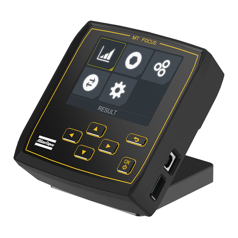
The controller has three buttons and a display, for setting of tightening parame-
ters.
Technical data
Ordering No 8432085003
Overall width N/A mm
Voltage - V

MT Focus 400 EN Product information
© Atlas Copco Industrial Technique AB - 9836 791600 00 5
Power 240 W
Motor voltage - V
Motor power - W
Weight 0.850 kg
Weight 1.88 lb
Accessories
Included accessories
ToolsTalk MT 8432 0831 30
USB Cable 4222 1238 02
Connector assembly 4216 2130 80
RS232 Cable 4216 2174 80
Optional accessories
Power supply 8432 0830 93
Wall bracket for MT Focus 400 8432 0833 83
I/O adapter 4216 2179 80
Remote control 8432 0830 08
I/O-Y cable 8432 0831 99
Service intervals
Service recommendations
Overhaul and preventive maintenance is recommended at regular intervals. See
the Preventive maintenance section for detailed information regarding over-
haul of your tool and specific parts. If the machine is not working properly, it
should immediately be taken away for inspection. At the overhauls, all parts
should be cleaned accurately and defective or worn parts should be replaced.

Installation EN MT Focus 400
6© Atlas Copco Industrial Technique AB - 9836 791600 00
Installation
Installation instructions
Basic set-up
NOTICE Always disconnect the USB connector before connecting or discon-
necting the power supply plug.
NOTE
• Some functions in the controller, such as the built-in clock, are powered
by a built-in battery. The charging time is 5 hours and the function is
maintained for 100 days if not recharged.
Controller connectors
1. USB: PC, connected with a USB cable.
2. POWER: Power supply connection.
3. RS232-C: Serial interface, for various accessories.
4. VP: Vacuum pump connection.
5. Tool, connected with the tool cable.
6. I/O: Single digital input for special purpose.
7. DIGITAL I/O: Connection for various accessories.
8. Connection for ESD protective wrist strap

MT Focus 400 EN Installation
© Atlas Copco Industrial Technique AB - 9836 791600 00 7
NOTE
• The torque measuring function in the controller is sensitive to strong
magnetic fields. Do not place magnetic items, for example bits, on or
near the controller.
NOTICE Make sure the cable is not bent more than a radious of 55 mm (2.2 in).
Connecting accessories
CAUTION
• The internal 24 V supply can be loaded with max 700 mA. If the sum of all
loads tend to exceed this value - use an external +24 V source.
Serial interface (RS232-C)
3-pole socket connector for the serial interface.
COM port settings: 115200Baud, 8Data bits, 1Stop bit, No parity, No hand-
shake.
Use a 3-pole pin plug from the Binder 719 Series.

Installation EN MT Focus 400
8© Atlas Copco Industrial Technique AB - 9836 791600 00
Pin Signal Description
1 TxD Transmitted data
2 GND Data ground
3 RxD Received data
Vacuum pump output (VP)
5-pole socket connector for the connection of Atlas Copco Vacuum pump
VPX6 (24 V, 600 mA).
Use a 5-pole pin plug from the Binder 719 Series.
Pin Output Description Default
1 +24 V Internal +24 V
2 +24 V Internal +24 V
3 Pump on Digital output
4 GND (0 V) Internal 0 V
5 GND (0 V) Internal 0 V
Configurable single input (I/O)
5-pole pin connector, configurable, e.g. as input for foot switch.
For information on configuration of the input, see ToolsTalk MT - Reference -
I/O status.
Use a 5-pole socket plug from the Binder 719 Series.
NOTICE
• This input is not opto-isolated.
Input resistance 10 kΩ
NOTICE
• If used to reset the tool, the signal duration must be more than 40 ms.
Pin Output Description Default
1 +24 V Internal +24 V
2 GND (0 V) 0 V output
3
4
5 Digital in Digital input Start tightening

MT Focus 400 EN Installation
© Atlas Copco Industrial Technique AB - 9836 791600 00 9
A 2 wire switch (e.g. a reed switch) is connected to pin 1 and 5.
A sensor with PNP output is connected to pin 1, 2 and 5.
Configurable digital inputs and outputs (DIGITAL I/O)
15-pole D-sub socket connector for configurable signals.
Use a 15-pole D-sub pin plug.
Voltage range 11-30 VDC
Input resistance >5 kΩ
Output resistance 23-35 Ω
Output current protection 120 mA max. peak/continuous current, over current
protected.
Input response time <25 ms (with de-bouncing filter)
Output response time <5 ms
NOTICE
• If the max. current is exceeded, the output voltage will switch off. This
can be resolved by switching the output off and on again.
Pin I/O Description Default
1 INT 24V Internal 24 V supply
2 EXT-OUT-COM0 External common line for
outputs
3 EXT-OUT0 Configurable Busy
4 EXT-OUT1 Configurable Tightening OK
5 EXT-OUT2 Configurable Tightening NOK
6 EXT-OUT3 Configurable Batch OK
7 Not used
8 EXT-IN0 Configurable Start tightening
9 EXT-IN1 Configurable Reset tool
10 EXT-IN2 Configurable Start loosening
11 EXT-IN3 Configurable Reset batch
12 Not used
13 Not used
14 EXT-IN-COM0 External common line for
inputs
15 DGND Internal ground

Installation EN MT Focus 400
10 © Atlas Copco Industrial Technique AB - 9836 791600 00
For information on configuration on the outputs and inputs, see ToolsTalk MT
- Reference - I/O status.
NOTICE
• All inputs are opto isolated.
• If used to reset the tool, the signal duration must be more than 40 ms.
• Interface connection can be connected in PNP mode (source type, posi-
tive logic), or in NPN mode (sink type, negative logic).
PNP mode
I/O Description
INT -24V +24 V output
EXT-OUT-COM0 Connect to INT +24V
or external +24 V
(not at the same time)
EXT-OUT0...EXT- OUT3 The outputs will be connected to the external +24 V
when activated.
EXT-IN0...EXT- IN3 The inputs will be activated by a +24 V signal applied
to the input pin.
EXT-IN-COM0 Connect to DGND
or external 0 V.
DGND 0 V output
NPN mode

MT Focus 400 EN Installation
© Atlas Copco Industrial Technique AB - 9836 791600 00 11
I/O Description
INT -24V +24 V output
EXT-OUT-COM0 Connect to DGND
or external 0 V.
EXT-OUT0...EXT- OUT3 The outputs will be connected to the external 0 V
when activated.
EXT-IN0...EXT- IN3 The inputs will be activated by a 0 V signal applied to
the input pin.
EXT-IN-COM0 Connect to INT +24V
or external +24 V
(not at the same time)
DGND 0 V output
Mechanical installation of controller
The controller can be used in three ways:
• Standing on a work bench.
• Attached to a vertical surface using the wall bracket.
• Attached to a vertical surface using screws from the rear side.
Wall bracket attachment
1. Attach the bracket to the surface using four 5 mm screws.
2. Pull out the plunger of the underside of the bracket and slide the controller
into the bracket.
3. The controller is held in placed by the plunger when released.
Rear screw attachment
1. Remove the two crews holding the controller foot.
2. Drill two 5 mm holes in the surface, corresponding to the holes in the con-
troller rear side. Leave space over the holes for the connectors and the
sound opening.
3. Attach the controller to the surface, preferrably with the removed screws.
NOTICE
• The screws must not protrude into the controller more than 10 mm.
Installation requirements

Operation EN MT Focus 400
12 © Atlas Copco Industrial Technique AB - 9836 791600 00
Operation
Ergonomics
Ergonomic guidelines
1. Take frequent breaks and change work positions frequently.
2. Adapt the workstation area to your needs and the work task.
• Adjust for convenient reach range by determining where parts or tools
should be located to avoid static motion.
• Use workstation equipment such as tables and chairs appropriate for the
work task.
3. Avoid work positions above shoulder level or with static holding during as-
sembly operations.
• When working above shoulder level, reduce the load on the static mus-
cles by reducing the weight of the tool, using for example torque arms,
hose reels or weight balancers. You can also reduce the load on the static
muscles by holding the tool close to the body.
• Make sure to take frequent breaks.
• Avoid extreme arm or wrist postures, particularly for operations requir-
ing a degree of force.
4. Adjust for convenient field of vision by minimizing movement of the eyes
and head during the work task.
5. Use the appropriate lighting for the work task.
Configuration
Please refer to User guide 9836 5637 01: ToolsTalk MT.
Operating instructions
Start
Press and hold the OK button (A) on the controller until the display lights up.
The system initializes. All basic functions are checked and displayed during ini-
tialization.

MT Focus 400 EN Operation
© Atlas Copco Industrial Technique AB - 9836 791600 00 13
CAUTION
• The spindle rotates when the system is switched on and the tool is calibrat-
ing.
After successful initialization, the system is ready for use.
Controller
NOTICE
• PSets are stored in the controller. The controller is initially programmed
with a number of default PSets that will work on any tool type.
• If a PSet is changed in any way, it will be assigned to the connected tool
type. If a tool of a different type is connected, this PSet can not be used.
Another PSet must then be choosen, or the PSet must be reconfigured,
either in Tools Talk MT, or using Auto-set.
Buttons and indicator
UP button:
• Enter the system menu
• Move the selection up
DOWN button:
• Enter the system menu
• Move the selection down
OK button:
• Switch the controller on and off
• Confirm the selection
STATUS indicator:
•Green - Tightening OK
•Blue - Batch finished
•Red - Error
Auto-set
1. Press either the UP or the DOWN button
2. Select Autoset in the menu.
3. Press OK.
4. If required, enter the password. Use the OK button to select a position and
the UP or the DOWN buttons to select the number.
5. Set the required tightening torque. Use the UP or the DOWN buttons to set
the torque.
6. Press OK.
7. Check that the correct PSet is shown. If so, select yes and press OK.
If not, return by selecting no and pressing OK.

Operation EN MT Focus 400
14 © Atlas Copco Industrial Technique AB - 9836 791600 00
8. Perform three tightenings.
NOTICE
• Each tightening should be done using a new joint.
9. If tightenings are not successful, repeat the tightening. if all tightenings are
successful, Auto-set done is shown.
10. If the speed is to be changed, press the DOWN button and use the UP or
the DOWN buttons to set the speed. Press OK to continue.
11. If the min. angle is to be changed, use the UP or the DOWN buttons to set
the min. angle. Press OK to continue.
12. If max. angle is to be changed, use the UP or the DOWN buttons to set the
max. angle. Press OK to continue.
13. If the trigger torque for angle counting is to be changed, use the UP or the
DOWN buttons to set the trigger torque for angle counting. Press OK to
continue.
14. In order to revise the settings, repeat steps 10-13.
15. Press OK to finish.
Select program set (PSet)
1. Press either the UP or the DOWN button
2. Select Select PSet in the menu.
3. Press OK.
4. If required, enter the password. Use the OK button to select a position and
the UP or the DOWN buttons to select the number.
5. Select the required program set.
6. Press OK.
Batch control
To set the batch size:
1. Press either the UP or the DOWN button
2. Select Batch control in the menu.
3. Press OK.
4. Select Set batch size in the menu.
5. Press OK.
6. If required, enter the password. Use the OK button to select a position and
the UP or the DOWN buttons to select the number.
7. Select the number of tightenings in the batch.

MT Focus 400 EN Operation
© Atlas Copco Industrial Technique AB - 9836 791600 00 15
8. Press OK.
To increment the batch number:
1. Press either the UP or the DOWN button
2. Select Batch control in the menu.
3. Press OK.
4. Select Increment batch in the menu.
5. Press OK.
To decrement the batch number:
1. Press either the UP or the DOWN button
2. Select Batch control in the menu.
3. Press OK.
4. Select Decrement batch in the menu.
5. Press OK.
To reset the batch number:
1. Press either the UP or the DOWN button
2. Select Batch control in the menu.
3. Press OK.
4. Select Reset batch in the menu.
5. Press OK.
Auto-start
If Auto-start has been enabled from ToolsTalk, an extra menu option, Auto-
start, appears.
To activate Auto-start:
1. Select Auto-start control in the menu.
2. Press OK.
3. Select Auto-start ON.
4. Press OK.
To de-activate Auto-start:
1. Select Auto-start control in the menu.
2. Press OK.
3. Select Auto-start OFF.
4. Press OK.
To temporarily disable Auto-start:
Put a non-magnetic object in the hole (A) on the front of the controller, for ex-
ample a pencil.
The Auto-start function will resume when the object is removed.

Operation EN MT Focus 400
16 © Atlas Copco Industrial Technique AB - 9836 791600 00

MT Focus 400 EN Service
© Atlas Copco Industrial Technique AB - 9836 791600 00 17
Service
Maintenance
Preventing ESD problems
The components inside the tool and controller are sensitive to electrostatic dis-
charge. To avoid future malfunction, make sure that service and maintenance is
carried out in an ESD approved work environment. The figure below shows an
example of an appropriate service work station.
Service recommendations
Overhaul and preventive maintenance is recommended at regular intervals. See
the Preventive maintenance section for detailed information regarding over-
haul of your tool and specific parts. If the machine is not working properly, it
should immediately be taken away for inspection. At the overhauls, all parts
should be cleaned accurately and defective or worn parts should be replaced.
Maintenance
There are certain general maintenance procedures you should perform to keep
your MicroTorque system clean and operating at its efficiency.
The system is a sophisticated instrument with many sensitive components.
A built-in service reminder can be configured in Tools Talk MT. When it is
time to perform service on the tool, a reminder is shown on the controller dis-
play.
Preventive Maintenance:
• The system should never be exposed to harsh environment with rapid tem-
perature changes or excessive dust.
• Never expose the system to excessive vibration or high humidity.
• Prevent overheating by use only in the permitted temperature range. Do not
cover tool or controller or power supply.
• Cleaning of the tool and controller should be done regularly, but not with
aggressive cleanser.
• Check wear of the bit regularly.
• Replace worn cables immediately.
Tools which have been opened by anyone else than Atlas Copco Industrial
Technique AB, will not be serviced.
Calibration and preventive maintenance is recommended at regular intervals
once per year or after maximum 1.000.000 tightenings depending on which oc-
curs sooner.

Service EN MT Focus 400
18 © Atlas Copco Industrial Technique AB - 9836 791600 00
More frequent overhaul may be needed if the machine is used in heavy-duty op-
erations.
If the machine is not working properly, it should immediately be taken away for
inspection.
Repair
Controller
Required tools:
• Screwdriver T8
• Small flat-bladed screwdriver
Opening the cover
1. Remove the four screws indicated by circles.
Do not open the unit when faced down.
2. With the unit in upright position, open the housing carefully to the left.
Do not strain the flat cable from the front.
Do not loose the USB isolator.
Changing the front panel
1. Open the connector using a small screwdriver and carefully pull out the flat
cable.
2. Unscrew the tool holder.
3. • Peel off the front panel. You can press from the inside on the display
window.
• Clean the inside surface of the cover with spirit.
Do not loose the light pipe.
4. Peel off the protection covers from the self-adhesive panel.
• One cover protecting the self-adhesive sections.
• One cover protecting the inside of the transparent window.
• One cover protecting the outside of the transparent window.

MT Focus 400 EN Service
© Atlas Copco Industrial Technique AB - 9836 791600 00 19
5. Route the flat cable from the new front panel through the hole in the hous-
ing, attach the new front panel to the housing.
Make sure the light pipe is correctly positioned.
6. Mount the tool holder.
7. Insert the flat cable into the connector, and close the connector by pressing
in the movable part using a small screwdriver.
Changing the display
1. Open the connector by folding the movable part up and forward, and care-
fully pull out the flat cable.
2. Disconnect the white connector by pulling straight up.
3. Remove the display.
Do not loose the spacers.
4. Make sure the four spacers are correctly positioned and put the new display
in position. The small pins at the bottom of the display should rest in the
holes of the bottom spacers.
5. Connect the white connector.
6. Insert the flat cable into the connector.
Make sure the cable runs under the small tabs at each side of the con-
nector
7. Close the connector by turning the movable part back inte position.

Service EN MT Focus 400
20 © Atlas Copco Industrial Technique AB - 9836 791600 00
Closing the cover
1. Close the housing.
NOTICE
• Make sure the display and the USB isolator is in correct position.
• Make sure the flat cable does not get harmed.
2. Mount the four screws.
Other manuals for MT Focus 400
1
This manual suits for next models
1
Table of contents
Languages:
Other Atlas Copco Control Unit manuals

Atlas Copco
Atlas Copco MT Focus 400 Instruction sheet

Atlas Copco
Atlas Copco POWER FOCUS 6000 Instruction sheet

Atlas Copco
Atlas Copco G 4 Instruction sheet

Atlas Copco
Atlas Copco Power MACS Instruction sheet

Atlas Copco
Atlas Copco Power Focus 3000 User manual

Atlas Copco
Atlas Copco Power Focus 6000 LV User manual

Atlas Copco
Atlas Copco Power Focus 600 Instruction sheet