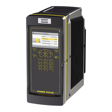
Atlas Copco Power Focus 6000 LV User manual

Power Focus 6000 LV
Printed Matter No. 9839 1081 01 Control and drive unit
Publication Date 2019-08-26
Valid from Serial No. A0450001 Product Instructions
Power Focus 6000 LV 8436180011
WARNING
Read all safety warnings and instructions
Failure to follow the safety warnings and instructions may result in
electric shock, fire and/or serious injury.
Save all warnings and instructions for future reference

2© Atlas Copco Industrial Technique AB - 9839 1081 01
Table of Contents
Product Information................................................................................................4
General Information ..........................................................................................4
Safety signal words ...............................................................................4
Warranty ................................................................................................4
Website..................................................................................................4
ServAid ..................................................................................................5
Safety Data Sheets MSDS/SDS............................................................5
Country of Origin ...................................................................................5
Dimensional Drawings...........................................................................5
Overview...........................................................................................................5
Normal Environmental Conditions .........................................................5
Mains fuse .............................................................................................5
Power ....................................................................................................6
Technical data .......................................................................................6
Network Connections ............................................................................7
Power consumption ...............................................................................7
Technical Product Data .........................................................................7
Service Overview..............................................................................................7
Service recommendations .....................................................................7
Installation ...............................................................................................................8
Installation Requirements .................................................................................8
Installation checklist...............................................................................8
Cable length recommendations - SL Tools ...........................................8
Front connections ..................................................................................8
Installation Instructions .....................................................................................9
Installing the controller...........................................................................9
Emergency stop button..........................................................................9
Configuring remote start for single or multiple controllers .....................9
Emergency stop in Power Focus 6000................................................13
Operation ...............................................................................................................17
Ergonomic guidelines .....................................................................................17
Service ...................................................................................................................18
Preventing ESD problems ..............................................................................18
Maintenance Instructions................................................................................18
Service recommendations ...................................................................18
Replacing the clock and calendar battery............................................18
Base board fuse..............................................................................................18
Wiring ..................................................................................................18
Repair Instructions..........................................................................................19
Wiring ..................................................................................................19
Recycling ...............................................................................................................20
Environmental Regulations.............................................................................20
Product Information EN Power Focus 6000 LV
4© Atlas Copco Industrial Technique AB - 9839 1081 01
Product Information
General Information
WARNING Risk of Property Damage or Severe Injury
Ensure that you read, understand and follow all instructions before operating the tool. Failure to follow
all the instructions may result in electric shock, fire, property damage and/or severe bodily injury.
►Read all Safety Information delivered together with the different parts of the system.
►Read all Product Instructions for installation, operation and maintenance of the different parts of
the system.
►Read all locally legislated safety regulations regarding the system and parts thereof.
►Save all Safety Information and instructions for future reference.
Safety signal words
The safety signal words Danger, Warning, Caution, and Notice have the following meanings:
DANGER DANGER indicates a hazardous situation which, if not avoided, will result in death or se-
rious injury.
WARNING WARNING indicates a hazardous situation which, if not avoided, could result in death or
serious injury.
CAUTION CAUTION, used with the safety alert symbol, indicates a hazardous situation which, if
not avoided, could result in minor or moderate injury.
NOTICE NOTICE is used to address practices not related to personal injury.
Warranty
■Product warranty will expire 12 months after the product is first taken into use, but will in any case ex-
pire at the latest 13 months after delivery.
■Normal wear and tear on parts is not included within the warranty.
■Normal wear and tear is that which requires a part change or other adjustment/overhaul during
standard tools maintenance typical for that period (expressed in time, operation hours or other-
wise).
■The product warranty relies on the correct use, maintenance, and repair of the tool and its component
parts.
■Damage to parts that occurs as a result of inadequate maintenance or performed by parties other
than Atlas Copco or their Certified Service Partners during the warranty period is not covered by the
warranty.
■To avoid damage or destruction of tool parts, service the tool according to the recommended mainte-
nance schedules and follow the correct instructions.
■Warranty repairs are only performed in Atlas Copco workshops or by Certified Service Partners.
Atlas Copco offers extended warranty and state of the art preventive maintenance through its ToolCover
contracts. For further information contact your local Service representative.
For electrical motors:
■Warranty will only apply when the electric motor has not been opened.
Website
Information concerning our Products, Accessories, Spare Parts and Published Matters can be found on
the Atlas Copco website.
Please visit: www.atlascopco.com.

Power Focus 6000 LV EN Product Information
© Atlas Copco Industrial Technique AB - 9839 1081 01 5
ServAid
ServAid is a portal that is continuously updated and contains Technical Information, such as:
■Regulatory and Safety Information
■Technical Data
■Installation, Operation and Service Instructions
■Spare Parts Lists
■Accessories
■Dimensional Drawings
Please visit: https://servaid.atlascopco.com.
For further Technical Information, please contact your local Atlas Copco representative.
Safety Data Sheets MSDS/SDS
The Safety Data Sheets describe the chemical products sold by Atlas Copco.
Please consult the Atlas Copco website for more information www.atlascopco.com/sds.
Country of Origin
For the Country of Origin, please refer to the information on the product label.
Dimensional Drawings
Dimensions Drawings can be found either in the Dimensional Drawings Archive, or on ServAid.
Please visit: http://webbox.atlascopco.com/webbox/dimdrw or https://servaid.atlascopco.com.
Overview
Normal Environmental Conditions
This product is designed to be safe under the following conditions:
■Indoor use
■Altitude up to 2 000 m
■Operating temperature +5 °C / +41 °F to +50 °C / +122 °F
■Storage temperature +5 °C / +41 °F to +50 °C / +122 °F
■Maximum relative humidity 80 % for temperatures up to 31 °C / 89 °F decreasing linearly to 50 % rel-
ative humidity at 40 °C / 104 °F
■Mains supply voltage fluctuations up to ±10 % of the nominal voltage
■Transient overvoltages up to the levels of overvoltage category ll
■Temporary overvoltages occurring on the mains supply
■Pollution degree 2
■Ingress protection rating: -
Mains fuse
Recommended mains fuses (power outlet):

Product Information EN Power Focus 6000 LV
6© Atlas Copco Industrial Technique AB - 9839 1081 01
Tool Mains voltage [V] Fuse [A]
ETD SL
ETP SL
ETV SL
ETF SL
115 10-16
230 10-16
If you are running the Power Focus 6000 LV as a stand-alone unit and trigger the tools manually (random)
it is normally possible to connect up to three Power Focus 6000 LV units to one power drop. If you are
synchronising the spindles you will need one drop for each Power Focus 6000 LV unit. The fusing in the
power drop shall be of time delay type.
Power
The Power Focus 6000 LV operates on a single-phase 100-240 VAC, 50-60 Hz.
The Power Focus 6000 LV has a wide input with PFC.
Total current drawn from Emergency Stop and 24V out concurrently may not exceed 2A.
Technical data
Weight 10.8 kg
Length 292 mm
Width 146 mm
Height 325 mm
Power rating 1300 W
Rated voltage 100-240 V
Power
The Power Focus 6000 LV operates on a single-phase 100-240 VAC, 50-60 Hz.
The Power Focus 6000 LV has a wide input with PFC.
Total current drawn from Emergency Stop and 24V out concurrently may not exceed 2A.
Power consumption
Power consumption depends on the speed and torque of the tool. High speed and torque increase power
consumption.
The Power Focus 6000 LV has a maximum power consumption of 1300W. In order to calculate the power
consumption at particular torques and speeds, use the following formula:
P Power Md Torque
n speed
The power consumption in idle mode has been measured with no controller or tool accessories con-
nected.
Mains fuse
Recommended mains fuses (power outlet):

Power Focus 6000 LV EN Product Information
© Atlas Copco Industrial Technique AB - 9839 1081 01 7
Tool Mains voltage [V] Fuse [A]
ETD SL
ETP SL
ETV SL
ETF SL
115 10-16
230 10-16
If you are running the Power Focus 6000 LV as a stand-alone unit and trigger the tools manually (random)
it is normally possible to connect up to three Power Focus 6000 LV units to one power drop. If you are
synchronising the spindles you will need one drop for each Power Focus 6000 LV unit. The fusing in the
power drop shall be of time delay type.
Network Connections
Factory LAN - 100/100 Mb/s
Service LAN - 100/100 Mb/s
Network Connections
Factory LAN - 100/100 Mb/s
Service LAN - 100/100 Mb/s
Power consumption
Power consumption depends on the speed and torque of the tool. High speed and torque increase power
consumption.
The Power Focus 6000 LV has a maximum power consumption of 1300W. In order to calculate the power
consumption at particular torques and speeds, use the following formula:
P Power Md Torque
n speed
The power consumption in idle mode has been measured with no controller or tool accessories con-
nected.
Technical Product Data
Technical Product Data can be found on either ServAid, or the Atlas Copco website.
Please visit: https://servaid.atlascopco.com or www.atlascopco.com.
Service Overview
Service recommendations
Preventive maintenance is recommended at regular intervals. See the detailed information on preventive
maintenance. If the product is not working properly, take it out of service and inspect it.
If no detailed information about preventive maintenance is included, follow these general guidelines:
■Replace any defective or worn parts

Installation EN Power Focus 6000 LV
8© Atlas Copco Industrial Technique AB - 9839 1081 01
Installation
Installation Requirements
Installation checklist
This Power Focus 6000 LV is a control and monitoring unit for electric assembly tools. The system
consists of:
■a Power Focus 6000 LV
■an IAM, Intelligent Application Module, containing software and configurations
■a tool cable, available in different models and lengths
■and a tool.
Cable length recommendations - SL Tools
Recommended cable lengths for SL tools is as follows:
Tool type Max cable length
Tensor SL (up to 12 Nm) 20m
Tensor SL (20 Nm) 15m
Front connections
Connections and switches behind the front cover of the Power Focus 6000 LV controller:
Controller connections behind the front cover

Power Focus 6000 LV EN Installation
© Atlas Copco Industrial Technique AB - 9839 1081 01 9
1. Remote start
2. Emergency stop
3. COM ports
4. Battery
5. Cable
6. USB port
7. IAM
8. Digital input
9. Digital output
10. I/O bus
11. Factory Ethernet port
12. Anybus CC
13. Power connector
Installation Instructions
Installing the controller
The controller must be positioned so that the power switch is easily accessible.
For maximum tool performance ensure that the controller is mounted so that free airflow is provided.
This will improve the cooling of the controller.
1. Mount the mounting plate on the wall or steel plate with three M6 screws. If mounting on a wall, make
sure to use the correct wall bracket (plug and screw). If mounting on a steel plate, make sure that the
plate is at least 2 mm thick.
2. Attach the controller to the mounting plate by tilting the controller and then insert the top flange of the
mounting plate into the slot on the rear of the controller. Drop the controller down to engage the lock-
ing mechanism.
3. Open the front access door of the controller.
4. Connect the power cable to the socket.
5. Connect the IAM to the socket on the back of the front access door.
6. Close the front access door.
7. Connect the tool cable to the socket on the underside of the controller.
8. Connect the power cable to a power supply (115/230 V)
9. Turn the power switch on
Emergency stop button
The supply disconnecting device may serve as an emergency stop when it is readily accessible to the op-
erator and it is of the type described in EN 60204-1:2006, 5.3.2 a), b), c) or d). When intended for such
use, the supply disconnecting device shall be colored red and have a yellow background. (Ref. EN
60204-1:2006, 10.7.5).
Configuring remote start for single or multiple controllers
The switch for remote start is found on the connector board located behind the front access door.
Whenever enabling remote start you must for safety reasons implement an emergency stop solution. For
more information about emergency stop, see Emergency stop in Power Focus 6000 LV.

Installation EN Power Focus 6000 LV
10 © Atlas Copco Industrial Technique AB - 9839 1081 01
When using portable hand-held or portable hand-guided tools (such as tools used with torque reac-
tion devices or dual trigger), remote start must be disabled by setting the switch on the controller to
OFF. This is done to make it impossible to override the safety function within the tools.
Emergency stop in Power Focus 6000
The Power Focus 6000 LV is equipped with an infrastructure needed to create an emergency stop func-
tion with redundant breaking according to EN ISO 13849-1 category 3 PL d. The emergency stop function
must be used when using remote start functionality.
The emergency stop function can be used with a supply disconnecting device (such as an EM Stop but-
ton). When pressed down, it breaks the supply voltage to the controller.
The emergency stop function can be used with either a single controller or up to 10 controllers in a single
emergency stop chain. In a multiple controller configuration the emergency stop signal is distributed from
the first controller to all interconnected controllers using the I/O bus interface. The last controller in the
chain returns a feedback signal to indicate that all controllers have received the emergency stop signal.
The event Emergency stop is displayed.
For the emergency stop there is a 24V DC output through the EM Stop terminal on the connector board.
Cabling
EM Stop button cables
Single/Multiple controllers Dimension Maximum length
Single 0.7 mm2 cable 400 meters
Multiple 1.5 mm2 cable 50 meters
I/O cables
For connecting multiple controllers with I/O-cables distributing the emergency stop signal, use the maxi-
mum length according to the following table:
AWG 22 cable Maximum total length
4 controllers 200 meters
5 controllers 140 meters
6 controllers 100 meters
8 controllers 70 meters
10 controller 50 meters
PIN configurations for emergency stop
The Power Focus has an external EM Stop interface and I/O-bus on the connector board that is located
behind the front access door.
The PIN configuration differs depending on if it is a single or multiple controller solution. Furthermore, for
the single controller the PIN configuration differs depending on if the controller is equipped with an EM
Stop button.
Single controller with EM Stop button
Connector: Phoenix, 6-pin Headers 3.5mm pitch
Use the following pin configuration:

Power Focus 6000 LV EN Installation
© Atlas Copco Industrial Technique AB - 9839 1081 01 11
Pin Use
1 Do not use
2 Do not use
3 Attach an emergency button be-
tween pin 3 and pin 4
4 See pin 3
5 Attach an emergency button be-
tween pin 5 and pin 6
6 See pin 5
7 Connect jumper between pin 7 and
pin 8
8 See pin 7
9 Connect jumper between pin 9 and
pin 10
10 See pin 9
Single controller without EM Stop button
WARNING Remote start switch must be set to OFF for this configuration
Connector: Phoenix, 6-pin Headers 3.5mm pitch
Use the following pin configuration:
Pin Use
1 Do not use
2 Do not use
3 Connect a jumper between pin 3
and pin 4
4 See pin 3
5 Connect a jumper between pin 5
and pin 6
6 See pin 5
7 Connect a jumper between pin 7
and pin 8
8 See pin 7
9 Connect a jumper between pin 9
and pin 10
10 See pin 9
Multiple controllers with EM Stop button
The PIN configuration differs depending on the location of the controller in the EM stop chain.
First controller with an EM Stop button connected
EM Stop button connector: Phoenix, 6-pin Headers 3.5mm pitch

Installation EN Power Focus 6000 LV
12 © Atlas Copco Industrial Technique AB - 9839 1081 01
EM Stop IO-cable connector: Molex Micro-Fit, 5-pin
Use the following pin configuration:
Pin Use
1 Do not use
2 Do not use
3 Attach an emergency button be-
tween pin 3 and pin 4
4 See pin 3
5 Attach an emergency button be-
tween pin 5 and pin 6
6 See pin 5
7 Connect a jumper between pin 7
and pin 8
8 See pin 7
9 Do not use
10 Do not use
Controllers between first and last
EM Stop IO-cable connector: Molex Micro-Fit, 5-pin
Remove plug or use the following pin configuration:
Pin Use
1 Do not use
2 Do not use
3 Do not use
4 Do not use
5 Do not use
6 Do not use
7 Do not use
8 Do not use
9 Do not use
10 Do not use
Last controller
EM Stop IO-cable connector: Molex Micro-Fit, 5-pin
Use the following pin configuration:

Power Focus 6000 LV EN Installation
© Atlas Copco Industrial Technique AB - 9839 1081 01 13
Pin Function
1 Do not use
2 Do not use
3 Do not use
4 Do not use
5 Do not use
6 Do not use
7 Do not use
8 Do not use
9 Connect a jumper between pin 9
and pin 10
10 See pin 9
Resetting emergency stop
Resetting an activated emergency stop is done by the software.
Emergency stop in Power Focus 6000
The Power Focus 6000 LV is equipped with an infrastructure needed to create an emergency stop func-
tion with redundant breaking according to EN ISO 13849-1 category 3 PL d. The emergency stop function
must be used when using remote start functionality.
The emergency stop function can be used with a supply disconnecting device (such as an EM Stop but-
ton). When pressed down, it breaks the supply voltage to the controller.
The emergency stop function can be used with either a single controller or up to 10 controllers in a single
emergency stop chain. In a multiple controller configuration the emergency stop signal is distributed from
the first controller to all interconnected controllers using the I/O bus interface. The last controller in the
chain returns a feedback signal to indicate that all controllers have received the emergency stop signal.
The event Emergency stop is displayed.
For the emergency stop there is a 24V DC output through the EM Stop terminal on the connector board.
Cabling
EM Stop button cables
Single/Multiple controllers Dimension Maximum length
Single 0.7 mm2 cable 400 meters
Multiple 1.5 mm2 cable 50 meters
I/O cables
For connecting multiple controllers with I/O-cables distributing the emergency stop signal, use the maxi-
mum length according to the following table:
AWG 22 cable Maximum total length
4 controllers 200 meters
5 controllers 140 meters
6 controllers 100 meters

Installation EN Power Focus 6000 LV
14 © Atlas Copco Industrial Technique AB - 9839 1081 01
AWG 22 cable Maximum total length
8 controllers 70 meters
10 controller 50 meters
PIN configurations for emergency stop
The Power Focus has an external EM Stop interface and I/O-bus on the connector board that is located
behind the front access door.
The PIN configuration differs depending on if it is a single or multiple controller solution. Furthermore, for
the single controller the PIN configuration differs depending on if the controller is equipped with an EM
Stop button.
Single controller with EM Stop button
Connector: Phoenix, 6-pin Headers 3.5mm pitch
Use the following pin configuration:
Pin Use
1 Do not use
2 Do not use
3 Attach an emergency button be-
tween pin 3 and pin 4
4 See pin 3
5 Attach an emergency button be-
tween pin 5 and pin 6
6 See pin 5
7 Connect jumper between pin 7 and
pin 8
8 See pin 7
9 Connect jumper between pin 9 and
pin 10
10 See pin 9
Single controller without EM Stop button
WARNING Remote start switch must be set to OFF for this configuration
Connector: Phoenix, 6-pin Headers 3.5mm pitch
Use the following pin configuration:

Power Focus 6000 LV EN Installation
© Atlas Copco Industrial Technique AB - 9839 1081 01 15
Pin Use
1 Do not use
2 Do not use
3 Connect a jumper between pin 3
and pin 4
4 See pin 3
5 Connect a jumper between pin 5
and pin 6
6 See pin 5
7 Connect a jumper between pin 7
and pin 8
8 See pin 7
9 Connect a jumper between pin 9
and pin 10
10 See pin 9
Multiple controllers with EM Stop button
The PIN configuration differs depending on the location of the controller in the EM stop chain.
First controller with an EM Stop button connected
EM Stop button connector: Phoenix, 6-pin Headers 3.5mm pitch
EM Stop IO-cable connector: Molex Micro-Fit, 5-pin
Use the following pin configuration:
Pin Use
1 Do not use
2 Do not use
3 Attach an emergency button be-
tween pin 3 and pin 4
4 See pin 3
5 Attach an emergency button be-
tween pin 5 and pin 6
6 See pin 5
7 Connect a jumper between pin 7
and pin 8
8 See pin 7
9 Do not use
10 Do not use
Controllers between first and last
EM Stop IO-cable connector: Molex Micro-Fit, 5-pin
Remove plug or use the following pin configuration:

Installation EN Power Focus 6000 LV
16 © Atlas Copco Industrial Technique AB - 9839 1081 01
Pin Use
1 Do not use
2 Do not use
3 Do not use
4 Do not use
5 Do not use
6 Do not use
7 Do not use
8 Do not use
9 Do not use
10 Do not use
Last controller
EM Stop IO-cable connector: Molex Micro-Fit, 5-pin
Use the following pin configuration:
Pin Function
1 Do not use
2 Do not use
3 Do not use
4 Do not use
5 Do not use
6 Do not use
7 Do not use
8 Do not use
9 Connect a jumper between pin 9
and pin 10
10 See pin 9
Resetting emergency stop
Resetting an activated emergency stop is done by the software.

Power Focus 6000 LV EN Operation
© Atlas Copco Industrial Technique AB - 9839 1081 01 17
Operation
Ergonomic guidelines
Consider your workstation as you read through this list of general ergonomic guidelines and see if you can
identify areas for improvement in posture, component placement, or work environment.
■Take frequent breaks and change work positions frequently.
■Adapt the workstation area to your needs and the work task.
■Adjust for convenient reach range by determining where parts or tools should be located to avoid
static load.
■Use workstation equipment such as tables and chairs appropriate for the work task.
■Avoid work positions above shoulder level or with static holding during assembly operations.
■When working above shoulder level, reduce the load on the static muscles by reducing the weight
of the tool, using for example torque arms, hose reels or weight balancers. You can also reduce
the load on the static muscles by holding the tool close to the body.
■Make sure to take frequent breaks.
■Avoid extreme arm or wrist postures, particularly for operations requiring a degree of force.
■Adjust for convenient field of vision by minimizing movement of the eyes and head during the work
task.
■Use the appropriate lighting for the work task.
■Select the appropriate tool for the work task.
■Use ear protection equipment in noisy environments.
■Use high-quality inserted tools or consumables to minimize exposure to excessive levels of vibration.
■Minimize exposure to reaction forces.
■When cutting:
A cut-off wheel can get stuck if the wheel is either bent or if it is not guided properly. Make sure to
use the correct flanges for cut-off wheels and avoid bending the wheel during cut-off operation.
■When drilling:
The drill might stall when the drill bit breaks through. Makes sure you use support handles if the
stall torque is too high. The safety standard ISO11148 part 3 recommends using something to ab-
sorb the reaction torque above 10 Nm for pistol grip tools and 4 Nm for straight tools.
■When using direct-driven screw or nutrunners:
Reaction forces depend on tool setting and joint characteristics. The ability to bear reaction forces
depends on the operator’s strength and posture. Adapt the torque setting to the operator's strength
and posture and use a torque arm or reaction bar if the torque is too high.
■Use dust extraction system or mouth protection mask in dusty environments.

Service EN Power Focus 6000 LV
18 © Atlas Copco Industrial Technique AB - 9839 1081 01
Service
Preventing ESD problems
The components inside the tool and controller are sensitive to electrostatic discharge. To avoid future mal-
function, make sure that service and maintenance is carried out in an ESD approved work environment.
The figure below shows an example of an appropriate service work station.
Maintenance Instructions
Service recommendations
Preventive maintenance is recommended at regular intervals. See the detailed information on preventive
maintenance. If the product is not working properly, take it out of service and inspect it.
If no detailed information about preventive maintenance is included, follow these general guidelines:
■Replace any defective or worn parts
Replacing the clock and calendar battery
The controller clock and calendar has a battery backup solution. The disposable battery is of type 3V
Lithium CR2032.
To replace the battery, do the following:
1. Open the front access door of the controller.
2. On the front access door, unscrew the screws on the clock/calendar cover and remove the cover.
3. Remove the old battery and replace it with a new battery of the same type.
4. Re-attach the cover and screws to the front access door.
5. Close the front access door.
Base board fuse
Base board fuse F101 characteristics:
250V AC/10 AT (mfr: Littelfuse type: 0215010.xxP)
Wiring
If it is necessary to change the plug on the mains cable, use the following wiring guide:
Color Input
Brown or black Live
Blue Neutral
Green and yellow Protective ground

Power Focus 6000 LV EN Service
© Atlas Copco Industrial Technique AB - 9839 1081 01 19
Warning! The power cable is the main disconnecting device and should be placed readily accessible to
the operator. Before you open a Power Focus unit make sure that the power cable is unplugged.
Warning! If the power supply cable needs to be replaced, only use an Atlas Copco original replacement
cord. Use of another cable may result in dangerous situations.
Repair Instructions
Wiring
If it is necessary to change the plug on the mains cable, use the following wiring guide:
Color Input
Brown or black Live
Blue Neutral
Green and yellow Protective ground
Warning! The power cable is the main disconnecting device and should be placed readily accessible to
the operator. Before you open a Power Focus unit make sure that the power cable is unplugged.
Warning! If the power supply cable needs to be replaced, only use an Atlas Copco original replacement
cord. Use of another cable may result in dangerous situations.

Recycling EN Power Focus 6000 LV
20 © Atlas Copco Industrial Technique AB - 9839 1081 01
Recycling
Environmental Regulations
When a product has served its purpose it has to be recycled properly. Dismantle the product and recycle
the components in accordance with local legislation.
Batteries shall be taken care of by your national battery recovery organization.
Recycling information
Number Part Recycle as
1 Screws Steel
2 Washer Steel
3 Chassis lid Aluminum
4 TPLC board WEEE
5 Shield plate Aluminum Zinc
6 USB Memory module, TPLC WEEE
This manual suits for next models
1
Table of contents
Other Atlas Copco Control Unit manuals

Atlas Copco
Atlas Copco POWER FOCUS 6000 Instruction sheet

Atlas Copco
Atlas Copco G 4 Instruction sheet

Atlas Copco
Atlas Copco Power Focus 3000 User manual

Atlas Copco
Atlas Copco MT Focus 400 Instruction sheet

Atlas Copco
Atlas Copco MT Focus 400 Instruction sheet

Atlas Copco
Atlas Copco Power MACS Instruction sheet

Atlas Copco
Atlas Copco Power Focus 600 Instruction sheet