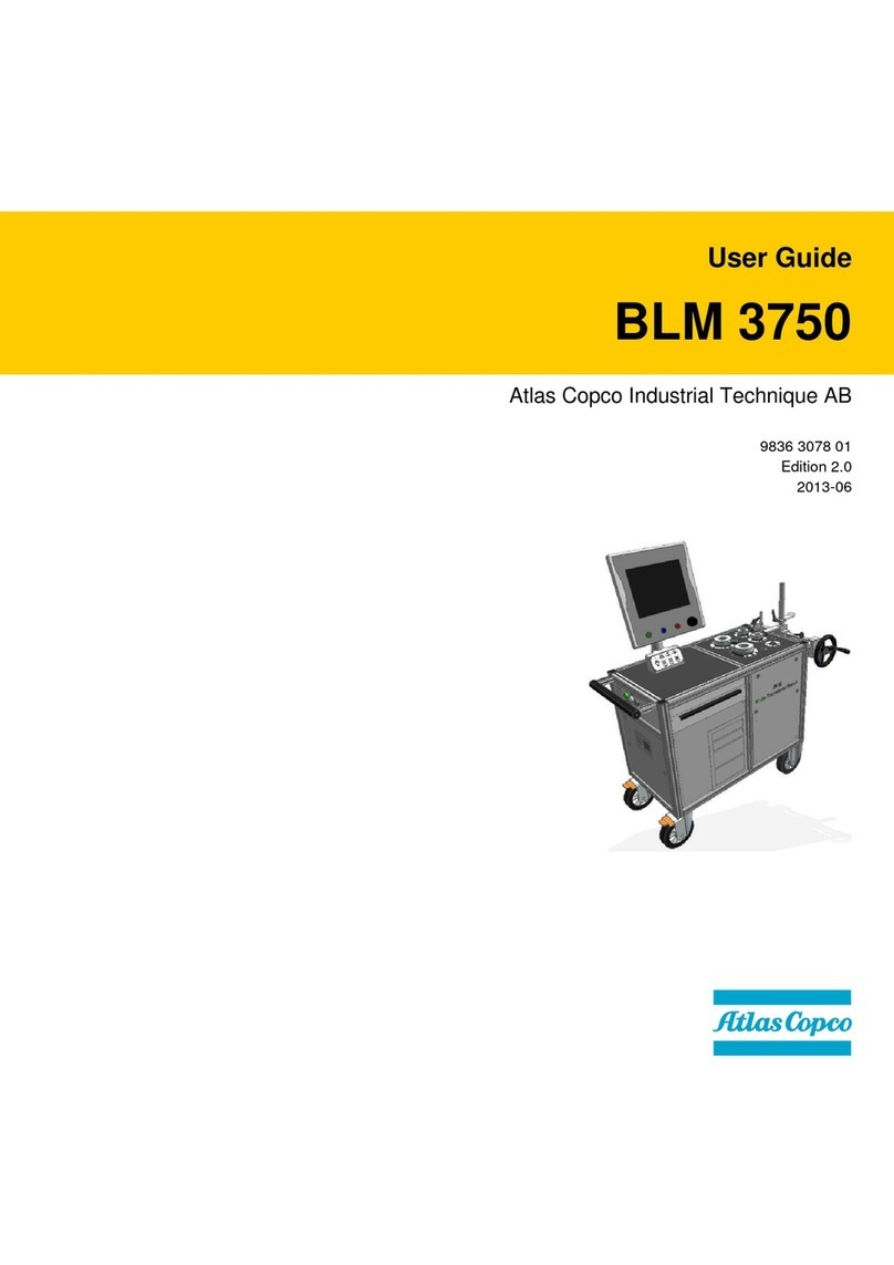
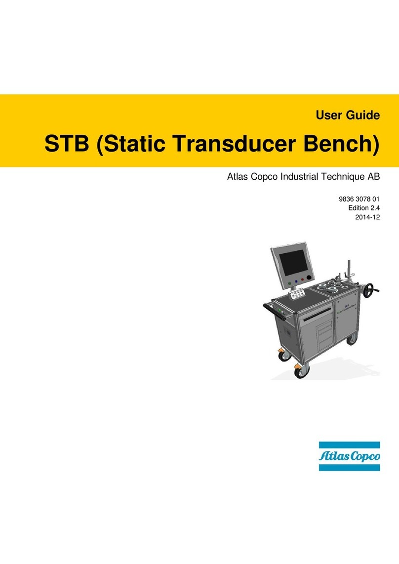
Atlas Copco STB User manual

User Guide
STB (Static Transducer Bench)
Atlas Copco Industrial Technique AB
9836 3078 01
Edition 2.11
2017-11


STB (Static Transducer Bench) User Guide Revision history
9836 3078 01 Edition 2.11 3 (82)
Revision history
Revision
Date
Author
Description
Reference
Minimum
Software version
2007-01
14-02-2007
M. Grippa
New Edition
2007-02
05-09-2007
M. Grippa
Test Setup section updated
2008-01
12-02-2008
M. Grippa
Introduction review
2009-01
17-09-2009
M. Grippa
Tool calibration function from Torque
Supervisor added, Hardware protection
key feature added.
4.0
2.0
11 June 2013
M. Grippa
New manual edition fully revised.
4.3
2.1
31 July 2013
M. Grippa
Product name updated, added
customization versions (par. 2.1)
4.3
2.2
7 April 2014
M. Grippa
PowerMACS calibration added (par. 8.1.1),
troubleshooting guide added (par. 13),
screenshots updated to new software version
5.0
2.3
30 June 2014
M. Grippa
Added controller serial number during
calibration (par. 8.1), troubleshooting
guide updated (par. 13)
5.1
2.4
19 December 2014
M. Grippa
Main menu screenshots updated
5.2
2.5
19 November 2015
C. Pacente
General screenshots review, Executing a
Free Test updated (par. 4),
Troubleshooting Guide updated (par. 13)
5.3
2.6
18 March 2016
C. Pacente
General screenshots review, Wrench test
setup updated –Default cut-off frequency
updated (par. 4.1.1), Impulse tools test
setup updated –Default cut-off frequency
updated (par. 4.2.1), Power tools test setup
updated –Default cut-off frequency
updated (par. 4.3.1)
5.4
2.7
5 December 2016
C. Pacente
General User Guide review, Main panel
updated (par. 3.10), Power supply /
batteries updated (par. 3.10.1), External
Transducer Setup updated (chapter 5)
5.7A
2.8
21 March 2017
R. Paderno
General User Guide review
5.8A

Table of Contents STB (Static Transducer Bench) User Guide
4 (82) 9836 3078 01 Edition 2.11
Revision
Date
Author
Description
Reference
Minimum
Software version
2.9
30 June 2017
C. Pacente
General User Guide review, Troubleshooting
Guide updated (chapter 13)
5.9A
2.10
20 September 2017
C. Pacente
Wrench test setup updated (par. 4.1.1)
5.10A
2.11
20 November 2017
C. Pacente
Windows compatibility update (Windows
10)
5.11A
Copyright Atlas Copco Industrial Technique AB
NOTE:This User Guide may be altered without further notice.
For further information log on to the Atlas Copco website: www.atlascopco.com
NOTE: In case of conflicts between translations of this User Guide, always refer to the official
English version.
Table of Contents
Table of Contents..................................................................................................4
SAFETY INFORMATION...................................................................................................6
BATTERIES INFORMATION according to European Regulation 2006/66/EC..................7
1INTRODUCTION.....................................................................................................8
1.1 About This Document...............................................................................................8
1.2 Reference Documents..............................................................................................9
1.3 Specifications ...........................................................................................................9
1.4 EC Declaration of Conformity .................................................................................11
2STB OVERVIEW...................................................................................................12
2.1 STB Versions..........................................................................................................16
2.1.1 STB AD standard.................................................................................................... 17
2.1.2 STB AD with custom keyboard and monitor........................................................... 17
3USER INTERFACES ............................................................................................18
3.1 Static transducers...................................................................................................18
3.1.1 Mechanical joint simulators..................................................................................... 19
3.2 LCD Monitor with Touch Screen.............................................................................20
3.3 Keyboard................................................................................................................21
3.4 Test Result LED .....................................................................................................21
3.5 External Transducers Connectors...........................................................................22
3.6 USB Ports...............................................................................................................23

STB (Static Transducer Bench) User Guide Table of Contents
9836 3078 01 Edition 2.11 5 (82)
3.7 Ethernet Port..........................................................................................................23
3.8 Serial Port RS232 .................................................................................................. 23
3.9 PC Reset Switch.................................................................................................... 24
3.10 Main Panel............................................................................................................. 24
3.10.1 Power supply / batteries..........................................................................................25
3.11 Hardware Protection Key: System Backup............................................................. 26
4EXECUTING A FREE TEST.................................................................................29
4.1 Testing Wrenches..................................................................................................33
4.1.1 Wrench test setup....................................................................................................33
4.2 Testing Impulse Tools............................................................................................ 37
4.2.1 Impulse tools test setup...........................................................................................39
4.3 Testing Power Tools ..............................................................................................40
4.3.1 Power tools test setup.............................................................................................41
5EXTERNAL TRANSDUCERS SETUP .................................................................43
6TRACES VIEWER................................................................................................47
7TEST REPORT.....................................................................................................50
8WORKING WITH Torque Supervisor .................................................................52
8.1 Tool Calibration Function .......................................................................................58
8.1.1 Power Focus / PowerMACS calibration ..................................................................62
9MAINTENANCE....................................................................................................65
10 TRANSDUCERS TEST PROCEDURE.................................................................66
11 APPENDIX A –TOOL TESTING GUIDELINES.....................................................67
11.1 Statistic Control Test.............................................................................................. 68
11.2 Cm-Cmk Test.........................................................................................................70
12 APPENDIX B - PROCESSES AND STATISTICS................................................71
13 TROUBLESHOOTING GUIDE .............................................................................75
14 ABBREVIATIONS ................................................................................................79
15 INDEX...................................................................................................................80

Safety Information STB (Static Transducer Bench) User Guide
6 (82) 9836 3078 01 Edition 2.11
SAFETY INFORMATION
WARNING: PLEASE READ CAREFULLY THE SAFETY INFORMATION
(No. 9836 5531 00) PRIOR TO USE THE PRODUCT AND PAY
ATTENTION TO THE SAFETY INSTRUCTIONS PROVIDED.
THE DOCUMENT IS APPLICABLE TO THE STB EXCEPT FOR THE
HYDRAULIC COMPONENTS NOT PRESENT IN THIS BENCH.

STB (Static Transducer Bench) User Guide Battery Information
9836 3078 01 Edition 2.11 7 (82)
BATTERIES INFORMATION according to European
Regulation 2006/66/EC
MAIN BATTERIES SPECIFICATION
TYPE: Two 12V 72 Ah gel/absorbed electrolyte type lead acid storage batteries
WEIGHT: 31.2 kg each
PC BATTERY SPECIFICATION (for all models)
TYPE: 3V lithium battery
WEIGHT: 5 g
WARNING: All the service activities, including those related to maintenance of the batteries,
must be executed only by Atlas Copco service personnel who has been properly trained.
NOTE: Once removed, the wasted batteries must be dismissed according to local regulations.

Introduction STB (Static Transducer Bench) User Guide
8 (82) 9836 3078 01 Edition 2.11
1 INTRODUCTION
1.1 About This Document
This document is a User Guide for the STB and it is divided into the main following parts:
Part
Name
Description
Chapter 1
Introduction
This part introduces this User Guide and details bench
technical specifications.
Chapter 2
Bench Overview
This part introduces the STB models and operating
principles.
Chapter 3
User Interfaces
This chapter provides an overview of the user interfaces
available on the STB (Transducers, Monitor, LEDs,
keyboard, ports and switches).
Chapter 4
Executing a Free Test
This part explains how to do a free test on wrenches,
pulse tools and power tools.
Chapter 5
External Transducers Setup
This part explains how to use an external transducer (for
example IRTT-B) connected to the bench.
Chapter 6
Traces Viewer
This part explains how to view and save the torque/time
traces.
Chapter 7
Test Report
This part explains how to generate and save test reports.
Chapter 8
Working with Torque
Supervisor
This part explains the use of the software when the
bench is working in conjunction with Torque
Supervisor.
Chapter 9
Maintenance
These parts list the maintenance tasks required by the
bench.
Chapter 10
Transducer test procedure
This part explains a procedure to ensure that the
transducers are working properly
Chapter 11
Tool Testing Guidelines
This part explains the principles of Statistic Control and
Cm-Cmk tests.

STB (Static Transducer Bench) User Guide Introduction
9836 3078 01 Edition 2.11 9 (82)
Part
Name
Description
Chapter 12
Process and Statistics
This part introduces a summary of the theory of process
and statistics.
Chapter 13
Troubleshooting guide
This part explains the most common errors, and the
warning/error messages that might be shown by the
bench software during the usage.
Chapter 14
and 15
Abbreviations and Index
List of abbreviations used in this User Guide and
alphabetical index
1.2 Reference Documents
The following is a list of important documents useful for a complete view of the product in all its
applications:
STB Safety Instructions (No. 9836 5531 00): Multilanguage safety instructions and declaration of
conformity
BLM Torque Seminar
Bench WEEE manual: Instructions about how to dispose of the product at the end of its life
Torque Supervisor User Guide
Torque Supervisor Client User Guide
SRTT-B User Guide
1.3 Specifications
MAIN FUNCTIONS
Testing in Statistic Control, Cm and Cmk measurements and tool calibration.
Extremely simple for the user, providing immediate results with colored lamps: Green: OK, Red: NOT OK
Storage of test traces and reports with date and time.
Ability to regulate and calibrate torque wrenches on the same test bench.
First peak detection function.

Introduction STB (Static Transducer Bench) User Guide
10 (82) 9836 3078 01 Edition 2.11
TECHNICAL
Torque range: 0.2 Nm ÷ 3000 Nm maximum (the real range depends from the bench transducers
configuration)
Torque measurement accuracy:
o0.5 % readout ±1 digit (from 20% to 100% of cell capacity)
o1 % readout ±1 digit (from 10% to 20% of cell capacity)
Torque overload capacity: 120%
Temperature stability of torque measurement: 0.1% of capacity/10 °C
Battery power supply (2 batteries 12 V 72 A/h): 16 hours’ endurance in operation mode
Recharging at 100 ÷ 230 VAC 50 ÷ 60 Hz; if the bench is switched off, recharging takes maximum 6
hours (not for JSB 3890)
AC Power Consumption: 1320 W maximum
AC Fuses:
oOne fuse 10A 500 VAC type gG
oOne fuse T8AL 250V (in AC power socket)
Overvoltage category: II
Battery Fuses: 2 fuses 25A 500 VAC type gG
Industrial PC
Indication “Low battery”
Dimensions / Weight of the STB (Static Transducer Bench): 1.55m (h) x 1.15m (w) x 0.53m (d) for
standard version, max 250 kg
INTERFACES
Touch screen LCD monitor
USB 2.0 ports
Network port 10/100 Base-T RJ-45
Serial port RS232
External transducer connectors for strain gauge torque/angle transducers; +5V supply for transducer
and encoder.
ENVIRONMENTAL
The following conditions must be observed during operation:
Internal Use only
Environmental Class: II

STB (Static Transducer Bench) User Guide Introduction
9836 3078 01 Edition 2.11 11 (82)
Ambient Temperature: 5 to 40°C
Atmospheric humidity: 95%, non-condensing
Altitude: Up to 2000m
CALIBRATION CERTIFICATE
The STB Benches are provided with an Atlas Copco BLM calibration certificate.
Optional ACCREDIA (ex SIT) certification is available on request and by agreement.
Atlas Copco BLM is an ACCREDIA calibration center.
1.4 EC Declaration of Conformity
The STB Benches are in conformity with the requirements of the council Directives on 06/22/1998 on the
approximation of the laws of the Member States relating:
2006/95/EC LVD - Low Voltage Directive
2004/108/EC Electromagnetic Compatibility
2011/65/EU The restriction of the use of certain hazardous substances in
electrical and electronic equipment
The STB Benches comply with the following normative:
EN 55011:2009+A1:2010 Industrial, scientific and medical equipment. Radio-frequency
disturbance characteristics. Limits and methods of measurement.
EN 61000-3-3:2008 Limitation of voltage changes, voltage fluctuations and flicker in public
low-voltage supply systems, for equipment with rated current <= 16 A
per phase and not subject to conditional connection.
EN 61000-3-2:2006 Limits for harmonic current emissions (equipment input current <= 16
A per phase).
EN 61326-1:2006 Electrical equipment for measurement, control and laboratory use –
EMC requirements –Part 1: General requirements
IEC 61010-1:2010 Safety requirements for electrical equipment for measurement, control,
and laboratory use - Part 1: General requirements

STB Overview STB (Static Transducer Bench) User Guide
12 (82) 9836 3078 01 Edition 2.11
2 STB OVERVIEW
The STB is ideal for controlling torque wrenches and screwdrivers according to ISO 6789 and SPC
standards or for calculating their Cm –Cmk.
The user-friendly software and the touch screen allow for immediate and simple operation.
The measurements taken are shown on a widescreen color LCD and the results are summarized by three
control lamps.
Since it is powered by batteries, the test bench may be used at any point along the assembly line.
Special PC software (Torque Supervisor) is available to allow the STB to be programmed with the tests to
be carried out during the week, and to receive their results. This software has been specifically developed
for controlling a large store of tools and allows Cm and Cmk or the test results to be filed in Statistic
Control, combining them with other information concerning the life of the tool (model, class, date of
purchase, presence in line or store, repairs, tests, etc.).
LCD monitor with touch screen
ISO Rig
Transducers
Drawers with
accessories
Test result lamps
Bench interfaces
Main panel

STB (Static Transducer Bench) User Guide STB Overview
9836 3078 01 Edition 2.11 13 (82)
The tests carried out are therefore fully traceable, including the X/R cards and the "history" of the tool, an
indispensable requirement for compliance with the standard ISO 9000. Contact your Atlas Copco sales for
any further information regarding this software.
The drawers contain a set of accessories:
Set of adapters. Number and size of adapters depend from the bench
transducers configuration.
Reaction bar: The reaction bar is a useful tool to provide the operator
with greater comfort and safety during testing; when the reaction bar is in
use, the tool under test reacts on the bar instead of reacting on the
operator’s arm.
It must be always used for testing tools over 15 Nm.
European and US AC power cables.
PC CDs: Windows CD and driver. Keep it in a safe place; it might be
used by Atlas Copco Service personnel during bench maintenance.

STB Overview STB (Static Transducer Bench) User Guide
14 (82) 9836 3078 01 Edition 2.11
An additional box is delivered with the bench:
This box contains safety instructions, manuals, certificates, passwords for software and other important
documents. It should be removed and kept in a safe place by the bench administrator.
It also contains the following tools:
Special tool to open the side panel in case of need to reset the PC.
Keys for the bench drawers.

STB (Static Transducer Bench) User Guide STB Overview
9836 3078 01 Edition 2.11 15 (82)
USB Recovery Key, containing the backup of the bench factory
configuration. This key must be kept in a safe place, and must be
available for service personnel during bench maintenance activities.
On the bench monitor desktop there are links to the main software(s) and some folders containing bench
documents and manuals:
Software and
documentation
Main software: it starts
automatically

STB Overview STB (Static Transducer Bench) User Guide
16 (82) 9836 3078 01 Edition 2.11
The software running on the STB Benches are:
Icon
Name
Description
Main software
The main software is started automatically and executes tool
testing. Refer to the paragraph “Executing a Free Test” for further
details.
Torque Supervisor
(Full, Light or
Client)
Torque Supervisor is an optional software to store the archive of
the tools to be tested, scheduling the tests, producing report and
statistics.
Refer to the paragraph “Working with Torque Supervisor” for
further details.
L_b_oil
This application, started automatically, monitors the battery
charge and the oil level inside the bench, and provides warnings if
necessary.
QAT Bench Backup
This application, started automatically, executes system backup.
Refer to the paragraph “Hardware Protection Key: system
backup” for further details.
Atlas Copco Remote
Service
This application can be used by the Atlas Copco service personnel
for maintenance activities.
2.1 STB Versions
The STB bench family includes different options and versions. The software and functions are the same
described in this manual. For customized bench with special software functions or additional components;
refer to this user guide and also to the specific attachment describing the customized functions.

STB (Static Transducer Bench) User Guide STB Overview
9836 3078 01 Edition 2.11 17 (82)
2.1.1 STB AD standard
This is the standard bench version. The most typical customization
is the number and capacity of transducers.
2.1.2 STB AD with custom keyboard and monitor
This version features a smaller chassis,
a monitor 12”, and a tiltable keyboard
installed outside the drawer.
The lamps are installed on the top of the
monitor, and the panel with the bench
interfaces is installed on the back side
of the monitor.
Keyboard
Monitor

User Interfaces STB (Static Transducer Bench) User Guide
18 (82) 9836 3078 01 Edition 2.11
3 USER INTERFACES
3.1 Static transducers
The standard STB bench features a set of static transducer SRTT-B:
Static transducers are designed to test:
Impulse power tools. When the
impulse tool has a shut-off valve, a
mechanical joint simulator is required.
Wrenches
Power tool, for those special cases in
which the test on the hydraulic would
be not possible. In this case, to
permit the tool to rotate, a
mechanical joint simulator must be
mounted on the static transducer.
To install a mechanical joint simulator, insert the simulator in the SRTT-B, and tighten the lever before
starting the test:
NOTE: Tighten the lever before entering the test window; the zero alignment is not performed
properly otherwise.
Tighten the lever, before
starting the test
Transducers

STB (Static Transducer Bench) User Guide User Interfaces
9836 3078 01 Edition 2.11 19 (82)
NOTE: For old benches, a static cell was installed instead of the SRTT-B:
The test philosophy on the static cell is the same of the one for SRTT-B. However, the static
cells are threaded and require the specific mechanical joint simulator (when a joint simulator is
needed).
3.1.1 Mechanical joint simulators
For each transducer SRTT-B on the bench, the two related mechanical joint simulators are provided.
Following are the two joint simulators provided for the SRTT-B 250 Nm:
TJ SRTT-B S –250
TJ SRTT-B H –250
Grey-Yellow
Grey-Black
Soft joint simulation
Hard joint simulation
For SRTT-B 1000 Nm, only one joint simulator is provided. Refer to the TJ SRTT-B User Guide for more
information about the joint simulators.

User Interfaces STB (Static Transducer Bench) User Guide
20 (82) 9836 3078 01 Edition 2.11
3.2 LCD Monitor with Touch Screen
The STB is equipped with a LCD monitor with touch screen.
To use all of the functions described in this manual, the touch screen can be used
to manage all of the operation (the bench keyboard/mouse, or external
keyboard/mouse can be used as well).
To edit a value in the bench software, proceed as following:
Press on the label (in this example Nom. Torque (Nm)) and the following virtual keyboard is shown:
Enter the desired value and press Enter to save.
When a virtual switch is displayed, simply touch or click to change its status.
Increase/decrease by one (active
either for mouse or touch screen)
Close virtual keyboard
Delete the last digit entered
Clear the display
Other manuals for STB
1
Table of contents
Other Atlas Copco Test Equipment manuals