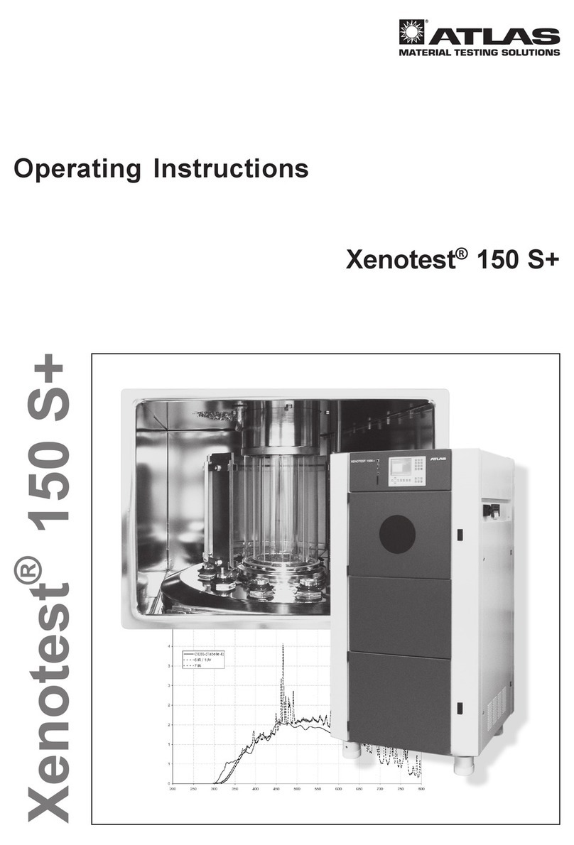
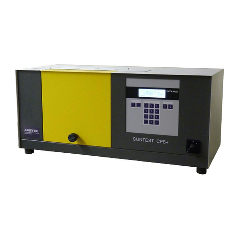
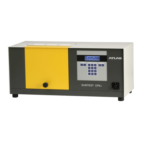
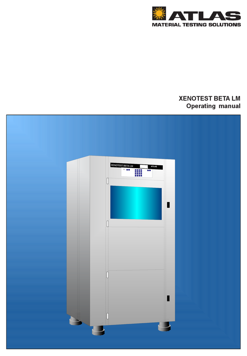
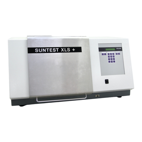
Atlas XENOTEST ALPHA User manual

XENOTEST ALPHA / ALPHA HIGH ENERGY
Operating manual

Operating manual XENOTEST ALPHA / ALPHA HIGH ENERGY ATLAS
Page 2

ATLAS Operating manual XENOTEST ALPHA / ALPHA HIGH ENERGY
Page 3
XENOTEST ALPHA / ALPHA HIGH ENERGY
Operating manual

Operating manual XENOTEST ALPHA / ALPHA HIGH ENERGY ATLAS
Page 4
Contents Page
1. Hints for this operating manual ................................................................................................. 7
1 1 Sign explanation 8
1 2 Safety instructions for the customer 9
1 3 Safety instructions for the operator 10
2. Features ...................................................................................................................................... 11
3. Setting up the unit .................................................................................................................... 12
3 1 Scope of delivery 12
3 2 Installation requirements 12
3 2 1 Laboratory 12
3 2 2 Unit air exhaust 12
3 2 3 Electrical supply 12
3 2 4 Water quality 13
3 2 5 Water supply 13
3 2 6 Space requirements 14
3 2 7 Unit dimensions 15
4. Description of the unit .............................................................................................................. 16
4 1 Front panel of the unit 16
4 1 1 Program control 17
4 1 2 Test chamber ALPHA 18
4 1 3 Test chamber HIGH ENERGY 18
4 2 Right side of the unit 20
4 3 Upper side of the unit 20
4 4 Left side of the unit 22
4 5 Rear panel 22
4 6 Ventilation ALPHA 24
4 7 Ventilation HIGH ENERGY 24
5. Options and accessories ......................................................................................................... 26
5 1 Options 26
5 1 1 Rain- and humidity function 26
5 1 2 Printer 27
5 1 3 Mains transformers 29
5 1 4 Interface 29
5 1 5 Turning mode gear 29
5 2 Accessories 30
5 2 1 Filter system 30
5 2 2 Standard set of sample holders 35
5 2 3 Special holder for thick samples 35
5 2 4 Sample holder for blue scale 36
5 2 5 Cover plates 36
5 2 6 Software package XENOVIEW 36
5 2 7 XENOSENSIV sensor 37
5 2 8 Adapter for XENOSENSIV sensor 37
5 2 9 Calibration adapter and end plug 38

ATLAS Operating manual XENOTEST ALPHA / ALPHA HIGH ENERGY
Page 5
Contents Page
6. Start up ....................................................................................................................................... 3
6 1 Filter variations 39
6 1 1 Fitting the filter to the latern 39
6 1 2 Insertion of the light exposure system 40
6 1 3 Insertion of the lamp and the lantern 40
6 1 4 Exchange of lamp 40
6 2 Water supply 42
6 3 Insert the XENOSENSIV sensor 42
6 4 Adjust the XENOSENSIV sensor 44
6 4 1 Fitting of the end plug 44
7. Function ..................................................................................................................................... 45
7 1 Measuring and control sensor system 45
7 1 1 Irradiance 45
7 1 2 Black standard temperature 45
7 1 3 Fan speed 45
7 1 4 Test chamber temperature 46
7 1 5 Test chamber humidity 46
7 2 Rain 46
7 3 Program control 47
7 4 Temperature diagrams 47
8. Programing example ................................................................................................................. 4
8 1 Task of the program 49
8 2 Solving the programing task 49
8 3 Program start 53
8 4 Print out of current program parameters 54
8 5 Change speed of blower during program operation 54
8 6 Stop a running program 54
8 7 Trouble shooting 55
. Setting up tests ......................................................................................................................... 58
9 1 Equip sample holders 58
9 2 Select unit parameters 58
10. Care and cleaning ..................................................................................................................... 5
10 1 Cleaning of quartz- and glass components 59
10 2 Cleaning the test chamber 59
10 3 Cleaning the water tank 59
10 4 Cleaning the air filter 59
11. Maintenance ............................................................................................................................... 60
12. List of options and accessories 60
12 1 Options 60
12 2 Accessories 61
13. Technical data............................................................................................................................ 62

Operating manual XENOTEST ALPHA / ALPHA HIGH ENERGY ATLAS
Page 6
Fig 1 Space requirements 14
Fig 2 Unit dimensions 15
Fig 3 Front side of equipment 16
Fig 4 Program control 17
Fig 5 Test chamber ALPHA 19
Fig 6 Test chamber HIGH ENERGY 19
Fig 7 Main switch 20
Fig 8 Right side of the unit 21
Fig 9 Left side of the unit 23
Fig 10 Ventilation scheme ALPHA 25
Fig 11 Ventilation scheme HIGH ENERGY 25
Fig 12 Water circuits 26
Fig 13 Printer 27
Fig 14 Printer parameter 28
Fig 15 Change of the paper roll 29
Fig 16 Mains transformers 29
Fig 17 XENOCHROME-filter system ALPHA and path of radiation 31
Fig 18 Spectral Distribution ALPHA
XENOCHROME 300 and CIE 85 32
Fig 19 Spectral Distribution ALPHA
XENOCHROME 270 and 320 32
Fig 20 Spectral Distribution HIGH ENERGY
XENOCHROME 300 and CIE 85 33
Fig 21 Spectral Distribution HIGH ENERGY
XENOCHROME 270 and 320 33
Fig 22 Absorption-filter system 34
Fig 23 Sunlight behind window glass 34
Fig 24 Light fastness of car interior 34
Fig 25 Spectral Distribution ALPHA
Absorption filter system 35
Fig 26 Standard sample holder 36
Fig 27 Special sample holder for thick samples 36
Fig 28 Sample holder für blue scale 37
Fig 29 Cover plates 37
Fig 30 XENOSENSIV-sensor 38
Fig 31 Adapter for XENOSENSIV sensor 38
Fig 32 Calibration adapter and end plug 38
Fig 33 Fitting the exposure system 41
Fig 34 Fitting the XENOSENSIV sensors 40
Fig 35 Calibration adapter 40
Fig 36 End plug 42
Fig 37 Humidity diagram ALPHA and HIGH ENERGY 46
Fig 38 Temperature fields ALPHA with XENOCHROME filter system 47
Fig 39 Temperature fields ALPHA with absorption filter system 48
Fig 40 Temperature fields HIGH ENERGY with XENOCHROME filter system 48
List of graphics Page

ATLAS Operating manual XENOTEST ALPHA / ALPHA HIGH ENERGY
Page 7
Safety instructions Unit set-up Unit description Start-up
Function Setting up tests Care and cleaning Maintenance
Options und accessory
ALPHA and HIGH
ENERGY features
Program example List of options and
accessories
1. Hints for this operating manual:
The maximum unit versions XENOTEST ALPHA LM-W and XENOTEST ALPHA HIGH ENERGY LM-
W are described in this operating manual.
For simplification these unit versions are merely called ALPHA or HIGH ENERGY (HE) in this operating
manual.
Options and accessories are presented in chapter 5 in this operating manual. In case you have a unit
version without much options and accessories, please skip the corresponding sections in this operating
manual.
Mod el T W HT LM-G LM-W HE-LM-G HE-LM-W
- Equipment feature
- Basic unit Alpha
- Basic unit ALPHA HIGH ENERGY
X
-
X
-
X
-
X
-
X
-
-
X
-
X
- Non-turning mode
- Non-turning mode for use with
XENOSENSIV
- Non-turning mode / turning mode
Non-turning mode / turning mode for use
wi th X EN OS ENSIV
-
-
X
-
-
-
X
-
-
X
-
-
-
X
-
-
-
-
-
X
-
X
-
-
-
-
-
X
- Control of lamp power in %
- Control of lamp rating in W/m²
X
-
X
-
-
X
-
X
-
X
-
X
-
X
Test chamber temperature
- controlled up to 45 °C
- controlled up to 70 °C
X
-
X
-
-
X
-
X
-
X
-
X
-
X
Measuring sensors at sample level
XENOSENSIV E(300-400 nm) and BST - - XXXXX
Stationary sensor for test chamber
temperature and relative humidity XXXXXXX
Ultrasonic humidification system XXXXXXX
Rain, pressureless - X - X X X X
Water supply with integrated
waterreservoir (capacity 70 l) XXXXXXX
Electrical versions:
- 200V, 50/60Hz
- 210V, 50/60Hz
- 220V, 50/60Hz
- 230V, 50/60Hz
- 240V, 50/60Hz
Must be indicated to customer specification !
Software versions:
- German
- Englisch
- French
Must be indicated to customer specification !

Operating manual XENOTEST ALPHA / ALPHA HIGH ENERGY ATLAS
Page 8
Safety instructions Unit set-up Unit description Start-up
Function Setting up tests Care and cleaning Maintenance
Options und accessory
ALPHA and HIGH
ENERGY features
Program example List of options and
accessories
1.1 Sign explanation
HINT!
HINT! is used when user tips and
helpful hints are given.
ATTENTION!
ATTENTION! is used when the non-compliance with i
nstructions may cause damage to the system.
DANGER!
DANGER! is used when the non-compliance with
instructions may cause danger to the user.
DANGEROUS VOLTAGE!
DANGEROUS VOLTAGE! is used when the non-compliance with instructions
may cause danger to the user because of dangerous voltage.

ATLAS Operating manual XENOTEST ALPHA / ALPHA HIGH ENERGY
Page 9
Safety instructions Unit set-up Unit description Start-up
Function Setting up tests Care and cleaning Maintenance
Options und accessory
ALPHA and HIGH
ENERGY features
Program example List of options and
accessories
1.2 Safety instructions for the customer
General:
• The electrical connection of the equipment has to be made by an electric specialist.
• Please note the special safety hints in the chapters "unit set-up" and "maintenance".
• Instruct the operating personnel with the help of this operating manual in the operation, function
and care of the unit. The unit may only be operated by instructed personnel. The operating
manual should be kept close to the unit.
• Inform the operating staff about accident prevention regulations regularly.
• For work at and with the unit the user needs instructions in his mother language based on the
operating manual (FRG: UVV VBG1 § 7 (2)).
• Before starting the unit ensure that the necessary requirements for a failurefree operation of the
unit are given. Observe the installation requirements in chapter 3.2 of this manual as well as valid
national laws, regulations and guiding principles.
Intended areas of application:
• The ALPHA and HIGH ENERGY units are designed for research, development and test laborato-
ries
• The ALPHA and HIGH ENERGY units shall only be used for the exposure and weathering of
materials in the intended areas of application.
• Inflammable or explosive materials must not be inserted into the unit. Do not insert materials
which despite their application as directed release toxical substances.
• Handling and usage contrary to the intended areas of application described in this operating manual
can present unforeseeable risk and should be avoided.
Maintenance and cleaning:
• The lateral two-leaf doors must only be opened by Xenotest personnel, an autorised customer
service or an electrical specialist.
• After one year it is necessary to subject the unit - especially the safety components - to regular
inspections.
• Mounting, extensions, replacements and repair work may only be carried out by Xenotest or an
authorised customer service engineer.
• The safety of the unit is only given, when the necessary maintenance and repair work is kept
within time and carried out by Xenotest or an authorised customer service engineer.

Operating manual XENOTEST ALPHA / ALPHA HIGH ENERGY ATLAS
Page 10
Safety instructions Unit set-up Unit description Start-up
Function Setting up tests Care and cleaning Maintenance
Options und accessory
ALPHA and HIGH
ENERGY features
Program example List of options and
accessories
1.3 Safety instructions for the operator
• The unit must be operated by instructed and authorised personnel only.
• Overheating and damage of the unit and the samples may occur, when the filters are not inser-
ted. Always insert the filters!
• Disconnect the unit from the mains, pull mains plug and secure against replugging, when fitting
the filter system, the lamp and the lantern as well as when carrying out care and cleaning work.
• Lamps, specimens, specimen holders and sensors heat up considerably during the weathering
tests. Protective gloves must therefore be worn when removing them to prevent injury to your
hands. This applies in particular to high temperature tests.
• When removing the lamp exhaust air hose while the unit is running UV radiation may emerge and
may cause irritation of the retina and the scin. Remove the lamp exhaust air hose only when the
unit is switched off.
• Please observe the special safety hints in the text of the chapters "unit description", "start-up",
"function", "setting-up tests", "care and cleaning".
The unit complies with the safety standards of:
• DIN VDE 0411 part 1 / 03.94
Measuring, Regulating, Controlling
Safety requirements for electric motor-operated measuring, regulating, controlling and
laboratory units.
• DIN VDE 0711 part 1 / 09.91
Lamps
• DIN VDE 0875 part 14 / 09.91
Limits and methods of measurement of radio disturbance characteristics of electric motor-
operated and thermal appliances for household and similar purposes, electric tools and similar
electric apparatus. (EN 55 014)
• DIN VDE 0871 part 11/09.87
Limits of radio disturbance and measuring methods for industrial, scientific and medical high-
frequency apparatus (EN 55 011).

ATLAS Operating manual XENOTEST ALPHA / ALPHA HIGH ENERGY
Page 11
Safety instructions Unit set-up Unit description Start-up
Function Setting up tests Care and cleaning Maintenance
Options und accessory
ALPHA and HIGH
ENERGY features
Program example List of options and
accessories
2. Features
a
Pos. Feature XENOTEST ALPHA LM
1Filter configuration Non-turning mode Warranty Turning mode Warranty
XENOCHROME 270 70 - 155 W/m² 135 W/m² 36 - 80 W/m² 70 W/m²
XENOCHROME 300 50 - 110 W/m² 100 W/m² 26 - 57 W/m² 51 W/m²
XENOCHROME 320 45 - 95 W/m² 80 W/m² 23 - 49 W/m² 42 W/m²
Absorption filters
7 IR
45 - 90 W/m² 75 W/m² 23 - 46 W/m² 38 W/m²
Absorption filters
4 IR + 3 window glass
50 - 95 W/m² 90 W/m² 26 - 49 W/m² 46 W/m²
Absorption filters
6 IR + 1 UV
40 - 85 W/m² 70 W/m² 21 - 44 W/m² 36 W/m²
2Rel. electrical power without
XENOSENSIV sensor
Continuously adjusted to preset value
53 - 120 %
3Test chamber temperature** 20 - 70 °C
4Black standard temperature ** 25 - 130 °C 25 - 100 °C
5Relative humidity** 10% - 95%
6Fan speed 500 - 2500 rpm
Pos. Feature XENOTEST ALPHA LM HIGH ENERGY
1Filter configuration Non-turning mode Warranty Turning mode Warranty
XENOCHROME 270 80 - 270 W/m² 270 W/m² 42 - 140 W/m² 140 W/m²
XENOCHROME 300 40 - 220 W/m² 190 W/m² 21 - 114 W/m² 99 W/m²
XENOCHROME 320 40 - 180 W/m² 170 W/m² 21 - 94 W/m² 88 W/m²
Absorption filters
7 IR
40 - 140 W/m² --- 21 - 72 W/m² ---
Window glass
10 WG
40 - 110 W/m² --- 21 - 57 W/m² ---
Absorption filters
4 IR + 3 window glass
40 - 140 W/m² --- 21 - 72 W/m² ---
Absorption filters
6 IR + 1 UV
40 - 140 W/m² --- 21 - 72 W/m² ---
2Rel. electrical power without
XENOSENSIV sensor
Continuously adjusted to preset value
53 - 120 %
3Test chamber temperature** 20 - 70°
4Black standard temperature ** 25 - 130 °C 25 - 100 °C
5Relative humidity** 10% - 95%
6Fan speed 500 - 2500 rpm
Note:
* Depending on the filtering, ATLAS guarantees a lamp lifetime of 1500 h for the values in bold type; unless
separate values are indicated, it is applicable for the whole adjustment range.
** The values achieveable depend on the chosen filter system, the irradiance settings and the laboratory
environmental conditions.

Operating manual XENOTEST ALPHA / ALPHA HIGH ENERGY ATLAS
Page 12
Safety instructions Unit set-up Unit description Start-up
Function Setting up tests Care and cleaning Maintenance
Options und accessory
ALPHA and HIGH
ENERGY features
Program example List of options and
accessories
3. Unit set-up
3.1 Scope of delivery
Supply in a suitable case. Scope of delivery of LM-
W versions:
1. Control system with display and operating
keyboard,
2. 1 Xenon lamp,
3. non-turning-, and turning mode gearing with
connection for XENOSENSIV sensor,
4. sensor to measure test chamber
temperature and rel. humidity,
5. XENOSENSIV sensor to measure the
irradiance and the black standard tem-
perature,
6. end plug for operation without
XENOSENSIV sensor,
7. adapter to fit XENOSENSIV in test cham-
ber,
8. outer cylinder made of special UV glass
(Suprax),
9. water tank,
10. Thermo printer,
11. interface RS232 / RS485
12. Technical documentation:
- Operating manual
- Software documentation
- Circuit diagrams
- Spare part lists
Sensitive components such as:
1. Xenon lamp,
2. XENOSENSIV sensor,
3. Outer cylinder,
are packed separately.
Additional sample holders and optical
filter sysytem are necessary for the run-
ning of the unit.
3.2 Space requirements
3.2.1 Laboratory
• Set up the unit in a air-conditioned and air-
filtered laboratory at 18°C - 25°C and a rela-
tive air humidity of max. 50%.
• Supply an amount of approx. 300m3 air per
hour via an air filter to the laboratory (filter
type EU 4).
• Keep the laboratory free of dust.
3.2.2 Exhaust air
• The exhaust hoses for the lamp and the test
chamber must be made of flexible
heatresistant material, as the temperatures
of the exhaust air may reach up to a max. of
120°C.
• The max. length of the exhaust hose is
limited to 3m including the option of two 90
degree bends.
• In case of longer exhaust air ducts or with
more than two 90 degree bends an external
blower is needed.
3.2.3 Electrical supply
The electrical connection to the mains has
to be made by an electrical specialist. The
unit is designed for a mains supply of
230V +/- 10%. Different voltages are
obtainable by fitting mains trans-formers.
Connection is ensured by (1,N,PE or 2,
PE), CEE (32A, 3pol.,6h).
• For the electrical supply observe UVV
VGB 4.
• Mains conditions have to agree with the
data on the name plate.
• Observe VDE- and technical connection
regulations of the energy supply compa-
nies.

ATLAS Operating manual XENOTEST ALPHA / ALPHA HIGH ENERGY
Page 13
Safety instructions Unit set-up Unit description Start-up
Function Setting up tests Care and cleaning Maintenance
Options und accessory
ALPHA and HIGH
ENERGY features
Program example List of options and
accessories
3.2.4 Water quality
The water must be of high-grade purity
to prevent deposits.
The use of ion exchange cartridges alo-
ne is not sufficient.
Regarding the water purity we refer to the mini-
mum requirements of some important standards,
such as DIN 53387 „Artifical light and weather fast-
ness of plastics“:
1. Electrical conductivy: < 5 µS/cm
2. PH value: 6-8
3. content of solid bodies < 1 ppm measured
as silicon dioxide.
3.2.5 Water supply
To ensure the functioning of the water
circuit and the humidification system,
the apparatus must be aligned by
means of its height adjustable feet.
By supply line:
fill the water tank (fig.9) with a pressure-resistant
hose to the water inlet of the tank (inner diameter
13mm, 3bar pressure).
without supply line:
fill the water tank manually.

Operating manual XENOTEST ALPHA / ALPHA HIGH ENERGY ATLAS
Page 14
Safety instructions Unit set-up Unit description Start-up
Function Setting up tests Care and cleaning Maintenance
Options und accessory
ALPHA and HIGH
ENERGY features
Program example List of options and
accessories
3.2.6 Space requirement (fig. 1)
Dimensions:
(Width x depth x height):
900mm x 780mm x 1800mm
For operating,- maintenance,- and repair work
please observe the necessary space requirements.
For adequate cooling of the xenon lamp,
take care that the air inlets and outlets at
the top and back side of the equipment
are not obstructed. Allow for the neces-
sary space for operation, maintenance
and repair of the equipment.
Figure 1: Space requirement
Set-up area Service area
HxHR min =2,5
x
x
Dimensions in
m
x
HR min
H
0,9
2,9
1,0 1,0
1,01,0
Hx=1,8 H R min =2,5
x
X = XENOTEST ALPHA LM and ALPHA HIGH ENERGY
= unit height = minimum laboratory height
0,9
2,9
1,0 1,0
2,8
1,0
0,81,0
0,8
x

ATLAS Operating manual XENOTEST ALPHA / ALPHA HIGH ENERGY
Page 15
Safety instructions Unit set-up Unit description Start-up
Function Setting up tests Care and cleaning Maintenance
Options und accessory
ALPHA and HIGH
ENERGY features
Program example List of options and
accessories
3.2.7 Unit dimensions (Fig. 2)
Figure 2: Unit dimensions (in mm)

Operating manual XENOTEST ALPHA / ALPHA HIGH ENERGY ATLAS
Page 16
Safety instructions Unit set-up Unit description Start-up
Function Setting up tests Care and cleaning Maintenance
Options und accessory
ALPHA and HIGH
ENERGY features
Program example List of options and
accessories
4. Description of the unit
Figure 3: Front side of equipment
1 Program control
2 Door locking test chamber
3 Door locking water tank
4 Height adjustable feet
4.1 Front side of equipment (fig. 3)
2
3
1
4

ATLAS Operating manual XENOTEST ALPHA / ALPHA HIGH ENERGY
Page 17
Safety instructions Unit set-up Unit description Start-up
Function Setting up tests Care and cleaning Maintenance
Options und accessory
ALPHA and HIGH
ENERGY features
Program example List of options and
accessories
The control panel on the front side of the apparatus
controls and regulates the course of the entered
weathering program. The program keyboard can
be locked during operation of the machine against
unauthorized access by means of a key-operated
switch.
Figure 4: Program control
4.1.1 Program control (fig. 4)
1 4-line LCD display for user guidance and
data display
2 Data key for data display
3 Print key to print out the stored program,
parameter measurements and system
status from the printer
4 Program input keyboard
5 Enter key to confirm the input values
6 Escape key
7 Key-operated switch to allow locking
of the keyboard when the system is
running
8 START key
9 Green LED light comes on when main
switch is on
10 STOP key
11 Red LED flashes when the program is
interrupted with the STOP key or when
the system is defective. The red LED is
continuously on when certain limit values
are exceeded
12 Key to interrupt the rotation of the
specimen holder carousel during a running
program resp. to move the carousel when
a program is interrupted (When door is
closed)
123
4
56
7
8910 11 12
0
1Start Sto p 123
456
789
0
ESCAPE ENTER
DAT A PRINT

Operating manual XENOTEST ALPHA / ALPHA HIGH ENERGY ATLAS
Page 18
Safety instructions Unit set-up Unit description Start-up
Function Setting up tests Care and cleaning Maintenance
Options und accessory
ALPHA and HIGH
ENERGY features
Program example List of options and
accessories
Open the test chamber by pressing the door lok-
king. A program is interrupted when the test cham-
ber door is opened while a unit is running.
Are located in the test chamber :
- Chosen outer cylinder (1),
- Xenon lamp (2),
- Filter lantern (3),
- 11 sample holders (4),
- sample holder mountings (5).
Function:
The samples rotate around the lamp and filter lan-
tern. In turning mode operation the samples are
turned by 180° per caroussell revolution.
Ventilation:
Test chamber and Xenon lamp are supplied by two
separate air flows.A uniform air ventilation is achie-
ved by an appropriate air flow (fig. 10 ventilation
scheme).
Temperature, humidification and rain:
Air is taken from the test chamber by an air ex-
haust hose (6), warmed up by a heating system
and humidified in the humidifier, and then sent back
to the test chamber by an air supply hose (7).
The maximum chamber humidity can be adjusted
up to 95% r. h. depending on the preset tempera-
ture.
The rain bar (8) mounted in the test chamber is
used to spray ultra-pure water in cyclical intervals
and without any pressure on to the specimens.
Sensors:
At sample level a XENOSENSIV sensor (9) for
measuring the irradiance in the range between
300-400nm and the black standard temperature in
the surface temperature range up to 130°C can
be fitted to the test chamber by means of an ad-
apter (10) (fig. 31). The sensor is connected to
the program control via a connection socket (11).
If no sensor is used the end plug must be fitted to
the connection socket (fig. 36).
A sensor to measure the test chamber tempe-
rature and rel. humidity (12) is mounted in the
upper rear of the test chamber. The sensors com-
bined with the program control guarantee control
of constant setting values.
Contrast to ALPHA:
Are locared in the test chamber:
- arc-shaped Xenon lamp (1)
Ventilation:
A uniform air ventilation of the sample area is achie-
ved by an air conduction plate (2) (fig. 11 venti-
lation scheme).
4.1.3 Test chamber HIGH ENERGY (fig. 6)
4.1.2 Test chamber ALPHA (fig. 5)

ATLAS Operating manual XENOTEST ALPHA / ALPHA HIGH ENERGY
Page 19
Safety instructions Unit set-up Unit description Start-up
Function Setting up tests Care and cleaning Maintenance
Options und accessory
ALPHA and HIGH
ENERGY features
Program example List of options and
accessories
2 31 45
67
8
910 11
12
1 arc-shaped
Xenon lamp
2 Air conduction plate
Figure 6: Test chamber HIGH ENERGY
Figure 5: Test chamber ALPHA
1 Outer cylinder
2 Straight Xenon lamp
3 Filter lantern
4 Sample holder
5 Sample holder mounting
6 Air exhaust hose
7 Air supply hose
8 Rain bar
9 XENOSENSIV sensor
10 Adapter
11 Connection socket
12 Sensor for test chamber
temperature and rel.
humidity
21

Operating manual XENOTEST ALPHA / ALPHA HIGH ENERGY ATLAS
Page 20
Safety instructions Unit set-up Unit description Start-up
Function Setting up tests Care and cleaning Maintenance
Options und accessory
ALPHA and HIGH
ENERGY features
Program example List of options and
accessories
4.2 Right-hand apparatus side ALPHA and HIGH ENERGY (fig. 8)
4.3 Apparatus top ALPHA and HIGH ENERGY (fig. 8)
Data output:
Data of stored programs as well as current measu-
ring values can be printed-out by a thermoprinter
(2). The interface (3) on the right-hand side of the
main switch provides for the data output and ex-
ternal computer control.
Electrical components:
The mains transformer of the humidifier (5), the
control transformer (6), a mains voltage inter-
ference filter (7) and the fuse base of the con-
trol voltage (8) are located below the test cham-
ber (4).
The power supply unit (10) of the lamp is moun-
ted below a protective wire mesh (9).
The mains transformer (11) and the lamp choke
(12) (not HIGH ENERGY unit) are located below
the power supply unit. The heating relay (14) is
seated next to the main contactor (13) and the
control of the test chamber fan (15). There is a
25 amps lamp fuse (16) protection and a 10 amps
heating fuse (17) protection. The operating hour
counter (18) records the operating time of the
equipment.
Ventilation:
The air intake for the lamp cooling (19) passes
through a filter pad in the equipment door.
The main switch (1) (fig.7) is located on the upper
left of the unit. Use this switch to disconnect the
unit from the mains in case of trouble.
The lateral two-leaf doors of the unit
must only be opened by XENOTEST, or
an authorized customer service engineer
or an electrical specialist.
Contact with live parts of a unit connec-
ted to the mains may involve electrical
shock.
Before opening the lateral two-leaf doors
disconnect unit from the mains. Unplug
the connection socket and secure
against replugging!
Figure 7: Main switch
0
1
The exhaust air flow of the lamp is evacuated at
the top of the unit via an exhaust air socket
(20) to the open. (note figure 10 and 11,
ventilation schemes).
This manual suits for next models
1
Table of contents
Other Atlas Laboratory Equipment manuals
Popular Laboratory Equipment manuals by other brands

Endress+Hauser
Endress+Hauser Analytik Jena PlasmaQuant MS Series Service manual

Terra Universal
Terra Universal Cleanroom Airlock Installation and operating guide

Swan Analytical Instruments
Swan Analytical Instruments AMI SAC254 Operator's manual

Keysight
Keysight M9383A Startup guide

Bullard
Bullard Edge Thermal Imager user manual

Caframo
Caframo BDC1850 instruction manual