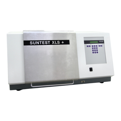
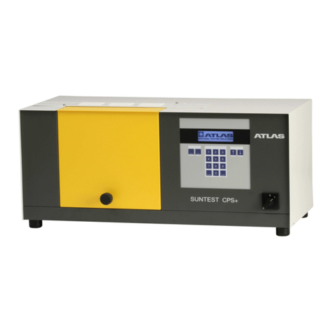
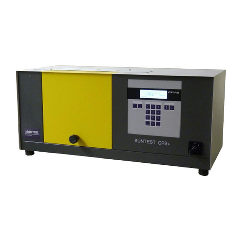
Atlas SUNTEST XLS User manual

Operating manual
SUNTEST XLS / XLS+

Operating manual SUNTEST XLS / XLS+
- 2 -
1 Notes for safe operation ............................................................................................................................... 4
1.1 Explanation of the pictorial signs ................................................................................................................ 6
1.2 Instruction for safe operation ...................................................................................................................... 7
2 Installation of equipment .............................................................................................................................. 8
2.1 Supplyschedule ......................................................................................................................................... 8
2.2 Packing material......................................................................................................................................... 8
2.3 Location requirements ................................................................................................................................ 9
3 Description of equipment ........................................................................................................................... 10
3.1 Description of Suntest XLS....................................................................................................................... 10
3.2 Description of Suntest XLS+ .................................................................................................................... 10
3.3 Components with similar construction SUNTEST XLS / XLS+ ..................................................................11
4 Function description ................................................................................................................................... 12
4.1 Radiation and Filtering.............................................................................................................................. 12
4.2 Ventilation circuits..................................................................................................................................... 12
4.3 Spectral distribution with additional filters ................................................................................................. 13
4.4 Sensor system in SUNTEST XLS+ .......................................................................................................... 14
4.5 Safety devices .......................................................................................................................................... 15
4.6 Safety markings ....................................................................................................................................... 15
5 Accessories ................................................................................................................................................. 16
6 Commissioning ........................................................................................................................................... 18
6.1 Mount the sample table ............................................................................................................................ 18
6.2 Assemble the radiation system................................................................................................................. 19
6.3 Connect to the power supply .................................................................................................................... 22
7 Operation and Shutdown............................................................................................................................ 23
7.1 Setting the equipment conditions.............................................................................................................. 23
7.2 Standard test procedure ........................................................................................................................... 23
7.3 Testing procedure with optional equipment............................................................................................... 23
7.4 Operation of SUNTEST XLS ................................................................................................................... 24
7.5 Operation of the SUNTEST XLS+ Program Controller .............................................................................24
7.6 Data transfer ............................................................................................................................................ 25
7.7 Shuttingdown........................................................................................................................................... 25
8 Calibration ................................................................................................................................................... 26
8.1 Calibration of the irradiance with the XenoCal Global-Sensor .................................................................. 26
8.2 Calibration of the irradiance with the Radialux Global-Sensor .................................................................. 27
8.3 Calibration of the black standard temperature .......................................................................................... 28
9 Cleaning / Consumables............................................................................................................................ 29
9.1 Cleaning ................................................................................................................................................... 29
9.2 Consumables / Spare parts ...................................................................................................................... 30
10 Maintenance ................................................................................................................................................ 31
10.1 Maintenance and care .............................................................................................................................. 31
10.2 Commissioning......................................................................................................................................... 31
11 Technical data.............................................................................................................................................. 31
Content Page

- 3 -
Operating manual SUNTEST XLS / XLS+
List of graphics Page
Fig.1 Description of Suntest XLS....................................................................................................................... 10
Fig. 2 Description of Suntest XLS+ .................................................................................................................... 10
Fig. 3 Components with similar construction SUNTEST XLS / XLS+ ..................................................................11
Fig. 4 Test chamber ............................................................................................................................................11
Fig. 5 Radiation and Filtering.............................................................................................................................. 12
Fig. 6 Ventilation circuits..................................................................................................................................... 12
Spectral distribution with additional filters ................................................................................................. 13
Fig. 7 Sensor system in SUNTEST XLS+ .......................................................................................................... 14
Fig. 8 Safety devices .......................................................................................................................................... 15
Fig. 9 Safety markings ....................................................................................................................................... 15
Fig. 10 Mount the sample table ............................................................................................................................ 18
Fig. 11 Components of the radiation system ........................................................................................................ 19
Fig. 12 Open the assembly compartment............................................................................................................. 19
Fig. 13 Installation of the optical filter ................................................................................................................... 20
Fig. 14 Installation of the Xenon lamp .................................................................................................................. 20
Fig. 15 Installation of the reflector mirror .............................................................................................................. 21
Fig. 16 Close the assembly compartment ............................................................................................................ 21
Fig. 17 Connect to the power supply .................................................................................................................... 22
Fig. 18 StandardTest Procedure .......................................................................................................................... 23
Fig. 19 Operation of SUNTEST XLS .................................................................................................................... 24
Fig. 20 Operation of the SUNTEST XLS+ Program Controller ............................................................................. 24
Fig. 21 Data transfer to a PC (pin configuration) .................................................................................................. 25
Fig. 22 Calibration of the irradiance with the XenoCal Global Sensor.................................................................. 26
Fig. 23 Calibration of the irradiance with the Radialux Global Sensor .................................................................. 27
Fig. 24 Calibration of the black standard temperature .......................................................................................... 28

Operating manual SUNTEST XLS / XLS+
- 4 -
Dear user,
Please note that certain kinds of work must only be carried out by personnel who are suitably qualified:
• The SUNTEST XLS and SUNTEST XLS+ may be operated only by trained and authorized laboratory per-
sonnel.
• The equipment should only be cleaned by trained personnel.
• This operating manual describes the SUNTEST XLS and the SUNTEST XLS+ weathering equipment.
• Please read the Operating manual carefully before using the SUNTEST XLS / XLS+. You will then be able to
exploit all the advantages that the equipment offers and prevent damage.
• In case unusual problems occur, that have not been treated in sufficient detail in this operating manual, please
contact the supplier for your safety.
1Notes for safe operation
ATLAS Material Testing Technology GmbH
Vogelsbergstr. 22
63589 Linsengericht
Germany
Phone ++ 49 / 6051 / 707-140
Fax ++ 49 / 6051 / 707-149

- 5 -
Operating manual SUNTEST XLS / XLS+
1Notes for safe operation
Dear User:
• This equipment has been manufactured according to the state-of-the-art and is operationally safe. Nonetheless,
there may be some danger from this equipment, especially if it is operated by personnel who are not adequately
trained, or if it is used in an improper manner, and not used for its intended purpose.
• For personnel working with or on this equipment, the operating agency must provide written instructions, in an
easy-to-understand form, based on these instructions, and make it available in the natural language of the em-
ployee (FRG:Accident PreventionAct, UVV VGB 1 § 7, 2).
• Based on these instructions, train the operating and cleaning personnel in the function, operation and mainte-
nance of this equipment.
• The contents of this operating manual are subject to change at any time without prior notice.
• The German version of this operating manual is binding in the case of translations in other, foreign languages.
• For reasons of safety, changes or modifications to the equipment on your own initiative are not permitted.
Please keep this operating manual carefully and accessibly in the vicinity of your equipment, so that safety
instructions and important information can be looked up at any time.
Trade marks:
All the trade marks in the instructions are the exclusive property of the respective manufacturers.
Copyright©
1999 ATLAS MTT GmbH • D-63589 Linsengericht • Germany
Edition dated:
November 1999

Operating manual SUNTEST XLS / XLS+
- 6 -
1Notes for safe operation
1.1 Explanation of the pictorial signs
Safety symbols will draw your attention to safety-cri-
tical operating errors.
Symbols used in the operating manual
WARNING!
Non-compliance with these can result in serious or even
fatal injury.
CAUTION!
Non-compliance with these can result in medium to light
personal injury or damage to property.
Note!
Provides usage tips and useful information.
CE - Conformance mark
Symbols on the equipment
CAUTION - Carefully follow operating instruc-
tions!
warns of possible danger.
Pull out power plug
warns against touching live parts of the equipment.
Do not open! Do not open!
warns against opening the gas pressure spring.
CE - Conformance mark

- 7 -
Operating manual SUNTEST XLS / XLS+
1.2 Instructions for safe operation
1Notes for safe operation
Please follow the safety instructions in the individual chapters.
Usage as authorized:
• SUNTEST XLS / XLS+ are used for exposure and weathering of material samples.
• The equipment is suitable for continuous operation.
• The equipment has been tested for electromagnetic compatibility and for installation in an industrial application.
Unauthorized usage:
• No substances or materials that are inflammable or that can explode should be used in the test chamber.
• No substances or materials that may release toxic substances in any form should be used in the test chamber.
• The equipment may not be used for drying or heating objects or foodstuffs.
Safety instructions for commissioning:
WARNING - Pull out the power plug:
Coming in contact with live parts can result in a possibly fatal electrical shock.
When assembling the radiation system, set the ON (I) / OFF (O) switch to the „OFF (O)“ position and pull out the
power plug. Secure the power plug from being inserted again.
WARNING - UV-radiation being emitted: :
If the sample table is not used, UV-radiation is emitted at the bottom of the equipment and can result in damage to the
skin of the face and the retina. The sample table should always be used when the equipment is running !
CAUTION - cuts and gashes:
The optical filters have sharp edges that can result in cut wounds.
Hand-gloves must be worn at all times when working on the radiation unit.
The equipment fulfills the following safety specifications:
• DIN EN 292, Part 1:1991-11, Part 2:1995-06
Safety of machinery
• DIN EN 61010 Part 1:1994-05
Safety requirements for electrical equipment for measurement, control and laboratory use. General requirements.
• DIN EN 50178 (VDE0160): 1998-04
Electronic equipment for use in power installations.
• DIN EN 50082 (VDE 0839) Part 1:1997-11
Electromagnetic compatibility (EMC), Generic immunity standard. Part 1: Residential, commercial and light indu-
stry. Part 2: Industrial area.
Disposal:
• Please dispose of the packing materials according to the applicable disposal guidelines. There is a list given in
chapter 2.2, „Packing Material“.
• Xenon lamps are special waste and may be sent toATLAS MTT B.V. for disposal.
• Old equipment contains re-usable materials. Therefore, please do not simply dispose of old equipment at the
nearest garbage dump, but ask your city or community administration about the possibilities of recycling.

Operating manual SUNTEST XLS / XLS+
- 8 -
2.1 Supply schedule
The weathering equipment is available in two versi-
ons, the SUNTEST XLS or SUNTEST XLS+ .
Thebasicequipmentofthe SUNTEST XLS consistsof:
• Xenon Lamp,
• Optical filter „coated quartz dish",
• UV reflector and light mirror,
• 2 Z-Rails,
• Sample table,
• Sensor for measurement and regulation of the irra-
diance (E),
• Control panel with rotary switch for stepless adjust-
ment of the irradiance, Xenon lamp operating hour
meter and ON/OFF switch of the Xenon lamp.
• ON / OFF switch
SUNTEST XLS+ is equipped with the following:
• Xenon Lamp,
• Optical filter „coated quartz dish“,
• UV-reflector and light mirror,
• Sample table,
• 2 Z-Rails,
• Sensorfor measurement and control ofthe irradiance
(E),
• Sensorformeasurementand control of the blackstan-
dard temperature (BST),
• Sensor for measuring the test chamber temperature
(CHT),
• Program controller with a display for displaying data
and keyboard for data input,
• ON (I) / OFF (O) switch,
• SerialRS 232-portfor connectingto aPC ora printer.
2Installation of equipment
2.2 Packing material
• Impregnated wood palette made of compound wood
• Polyethylene foil (PE)
• Polyethylene foam (PE)
• Corrugated cardboard
• Plastic wrapping ribbon (PP)

- 9 -
Operating manual SUNTEST XLS / XLS+
2Installation of equipment
2.3 Location requirements
Climatic conditions required for the place of installa-
tion:
• During continuous operation, the hot air emitted by
the air-cooling system results in a constantly chan-
ging climate in the room. Therefore, the SUNTEST
equipmentshould onlybe installedin air-conditioned,
sufficiently ventilated places of installation.
• The places of installation must be kept free of dust.
• The room temperature must be maintained between
18°C and 25°C.
• The max. relative humidity should be 70%.
The requirement for coolant air is as follows:
• Lamp cooling 250 m³/h,
• Air conditioner for the test chamber 340 m³/h.
Installation:
• Dimensions of equipment (width x depth x height):
930 mm x 500 mm x 485 mm,
• Weight of equipment approx. 80 kg,
• The equipment must be set up on a sufficiently stable
laboratory bench with a non-flammable support un-
derneath and the laboratory bench should be aligned
so that it is horizontal.
• Please lift the unit for any displacement to avoid that
the rubber feet fall off the fixing screws.
Caution - Overheating of the equipment:
Blocking of the air inlet and air outlets can result in
overheating and damage to the equipment!
When installing the equipment, the following mini-
mum distances to the neighboring walls or objects
must be maintained:
to the front 700 mm
to the back 500 mm
to both sides 300 mm
on top 400 mm.

Operating manual SUNTEST XLS / XLS+
- 10 -
!Covering hood
"Rotary switch for setting the irradiance
#Xenon lamp operating hour meter
$Switch for Xenon lamp
%ON (I) / OFF (O) switch
&Test chamber door
Figure 1
3Description of equipment
Figure 2
!Covering hood
"Control panel
#Numeric keypad
$Display
%ON (I) / OFF (O) Switch
&RS 232 port for data transfer to a PC
'Test chamber door
3.1 Description of SUNTEST XLS
SUNTEST XLS facilitates manual running of the testing
programs. The irradiance that has been set is controlled
at a constant value throughout the test duration.
Upper side of the equipment:
• Covering hood !of the assembly compartment for
the lamp and filter system.
Front side of the equipment:
• Rotary switch "for setting the irradiance,
• Xenon lamp operating hour meter #,
• ON/OFF switch $for Xenon lamp,
• ON (I) / OFF (O) switch %,
• Test chamber door &.
3.2 Description of SUNTEST XLS+
SUNTEST XLS+ is equipped with a microprocessor-ba-
sedcontroller for measurement andregulation and works
with software-controlled testing programs.
Upper side of the equipment:
• Covering hood !of the assembly compartment for
the Xenon lamp and filtering system.
Front side of the equipment SUNTEST XLS+:
• Control panel "with
• Numeric keypad #and
• Display $,
• ON (I) / OFF (O) switch %,
• RS 232 port &for data transfer to a PC or printer,
• Test chamber door '.

- 11 -
Operating manual SUNTEST XLS / XLS+
3Description of equipment
Figure 3
!Air outlet for Xenon lamp cooling
"Port for connecting the optional cooling equipment
/flooding equipment
#Power plug with connecting cable
$Air inlet opening - test chamber
%Air inlet opening Xenon lamp cooling
Figure 4
!Gas pressure spring
"Test chamber door
#Reflector
$Xenon lamp
%Photodiode for measurement of the irradiance
&Black standard sensor (BST)
'Air inlet for temperature control in the
test chamber
(Sample table
Test chamber: Fig. 4
• Gas pressure spring !for easy opening / closing the
test chamber door ".
• The reflector #is located in the test chamber, and
the Xenon lamp $at the top of the test chamber,
• The photo-diode %measures the irradiance,
• The black standard sensor (BST) &(only in XLS+)
measures the black standard temperature at sample
level,
• Air inlet 'for temperature control in the test
chamber,
• the sample table (is used for locating or fixing the
specimens.
3.3 Components with similar construc-
tion SUNTEST XLS / XLS+ Figure 3 / 4
The rear side of the equipment and the test chamber
are similar in design in both models.
Rear side of the equipment: Fig. 3
• Air outlet !of the Xenon lamp cooling,
• Port "for connecting the optional cooling device /
flooding device,
• Power plug with connecting cable #,
• Air inlet opening $of the test chamber,
•Air inlet opening %for Xenon lamp cooling.

Operating manual SUNTEST XLS / XLS+
- 12 -
• The specimens !are placed on the sample table ".
The radiation $is generated by the Xenon-Lamp #.
The radiation $is filtered through an optical filter
"coated quartz dish" %.
Note!
There are optional filters (see Chapter 5, „Accessories’)
available for various spectral distributions (see chapter.
4.1.3, „Spectral distribution with additional filters“).
• The UV-component of the radiation, that is directed
upwards, is reflected on the specimens !by the
mirrors &that are placed above the Xenon lamp #.
• The components of the non-dangerous IR-radiation
(heat radiation) are absorbed by an absorber, and re-
moved out of the equipment via the air circuit of the
Xenon lamp.
4Function description
Figure 5
!Specimens
"Sample table
#Xenon lamp
$Radiation
%Optical filter " coated quartz dish"
&Mirror
!Cooling air supply (inlet), test chamber
"Cooling air outlet, test chamber,
lower side of the device
#Cooling air supply Xenon lamp
$Cooling air outlet, Xenon lamp
4.1 Radiation and Filtering
4.2 Ventilation circuits
• The coolant air of the test chamber !is sucked in-
ward on the rear side of the equipment (see chapter
3.3, „Rear side of equipment“) through an air filter,
flows through the test chamber and exits at the bot-
tom of the equipment ".
• The coolant air of the Xenon lamp #is drawn in on
the rear side of the equipment (see chapter 3.3,
“Rear side of equipment”) through an air filter, flows
throughthe Xenon lampcompartmentandexitsagain
on the exhaust opening on the rear side $.
NOTE!
During continuous operation, the hot air emitted by the
air cooling system results in a continuous change in the
labboratory climate.
Figure 6
IR-Radiation
(heat radiation)
UV-Radiation and
visible light

- 13 -
Operating manual SUNTEST XLS / XLS+
4Function description
Figure: Spectra
4.3 Spectral distribution with
additional filters
0
1
2
3
4
5
6
200 300 400 500 600 700 800 900
Wavelength (nm)
Irradiance (W/(m²xnm))
UV-Special glass
CIE85 (Table 4)
SUNTEST XLS / XLS+
E (300nm - 800nm) = 765 W/m²
0
0,5
1
1,5
2
2,5
3
250 270 290 310 330 350 370 390 410 430 450
Wavelength (nm)
Irradiance (W/(m²xnm)
UV MAX
UV-Special glass
Special-window glass
SUNTEST XLS / XLS+
E (300nm - 800nm) = 765 W/m²

Operating manual SUNTEST XLS / XLS+
- 14 -
4Function description
4.4 Sensor system in SUNTEST XLS+
SUNTEST XLS+ has integrated sensors:
• Sensor for measuring and controlling the irradiance
(E) in the range 300 - 800nm,
• Sensor for measuring and regulating the black stan-
dard temperature (BST) in the range ambient tempe-
rature up to about 90°C,
• Sensor for measuring the test chamber temperature
(CHT).
Irradiance (E):
• During the testing, the irradiance is measured by a
photo-diode !and controlled electronically to achie-
ve a constant value.
Black Standard Temperature (BST)
• Duringthe testing, temperature measurementsareta-
ken continuously by the black standard-sensor (BST)
".
• The black standard temperature (BST) is controlled
via the speed of the test chamber ventilator.
Test chamber temperature (CHT):
• The test chamber temperature (CHT) is measured by
a temperature sensor in the exhaust air flow of the
test chamber.
• The test chamber temperature cannot be controlled.
The test chamber temperature is indicated in the dis-
play unit of the program controller.
Measurement data:
• The measured data can be transferred, with the te-
sting program running, via the RS 232-port #toa PC
or a printer with a serial interface.
!Photodiode for measurement of the irradiance
"Black standard-Sensor (SST)
#RS 232 port for data transfer
Figure 7

- 15 -
Operating manual SUNTEST XLS / XLS+
!ON (I) / OFF (O) switch
"Door switch for test chamber door
#Safety switch for covering hood
$Gas- pressure spring
4Function description
Figure 8
4.5 Safety devices
There are safety and protection devices that increa-
se the operational and functional safety of the equip-
ment:
• To switch off the equipment in an emergency, set the
ON (I) / OFF (0) switch !to position “OFF (0)”.
• A door switch switches off the equipment when the
test chamber door "is opened.
• Asafety switch interrupts the power supply when the
covering hood #is pushed back.
• The gas-pressure spring $on the door of the test
chamber stabilizes the door in its open position.
• A temperature safety device switches off the equip-
ment if there is a danger of the Xenon lamp getting
overheated because of insufficient cooling.
Figure 9
4.6 Safety markings
Please check whether the safety markings mentio-
ned below have been put on the equipment.
If any of the safety markings should be absent, plea-
se inform your supplier.
• The safety notice “Pull out power plug” !on the ab-
sorberprovides a warning about touching live partsof
the equipment.
• The safety notice “Warning of danger" "on the ab-
sorber warns about touching the radiation system
when it is hot and about sharp edges on the optical
filter and reflecting mirror.
• The safety notice “Warning of danger” #on the door
of the test chamber warns of a possible danger of
fingers getting caught in the door of the test chamber
if the door is closed abruptly, and of touching hot spe-
cimens.
So also, there is a warning about the dangers of the
UV-radiation being emitted if the sample table is not
fitted.
• The notice “Do not open!” $on the gas pressure
spring warns about opening the gas pressure spring,
which is under high tension.
4
2
1
3
!Pull out the plug
"Warning of danger
#Warning of danger
$Do not open
Nicht öffnen!

Operating manual SUNTEST XLS / XLS+
- 16 -
5Accessories
Item Accessories Description Ident no.:
1Sensors:
1.1 XenoCal UV sensor Measurement and calibration of the irradiance;
measurement range 300 - 400 mm 5500 7270
1.2 XenoCal Global sensor Measurement and calibration of the irradiance;
measurement range 300 - 800 mm 5500 7271
1.3 Adapter for XenoCal sensors Holding plate for insertion of the XenoCal sensor
in the testing chamber 5607 7895
1.4 Black standard sensor (BST) Measurement of the black standard temperature
(BST) 5600 1490
1.5 White standard sensor (WST) Measurement of the white standard temperature
(WST) with digital display 5600 1491
1.6 White standard sensor (WST) Measurement of the white standard temperature
(WST), (separate readout device required) 5607 7906
1.7 Adapter for SST and WST sensor Holding plate for inserting the BST and WST
sensors in the test chamber 5607 7928
1.8 XENOVIEW, serial 9-pole Software package for transferring the test
parameters to a PC 5607 6813
1.9 XENOVIEW, serial 25-pole Software package for transferring the test
parameters to a PC 5607 6812
2 Filter:
2.1 UV special glass In addition to the coated quartz dish for working
with wave lengths greater than 290 mm 5605 2371
2.2 Special window glass In addition to the coated quartz dish for working
with wavelengths greater than 310 mm 5605 2372
2.3 Solar standard Filter according to COLIPA and DIN 67501 5607 7759
2.4 Solar ID65 Filter for illuminating according to the ICH
Guideline 5607 7769
2.5 Uncoated quartz disk Instead of the coated quartz dish for higher
black standard temperatures 5605 2373
3 Testing table
3.1 Water-cooled sample table For illuminating temperature-sensitive materials 5607 8013
4 Covering sheet
4.1 Set of covering sheets Covering sheets for direct visual comparison of
the weathered and unweathered test areas 5607 7980

- 17 -
Operating manual SUNTEST XLS / XLS+
5Accessories
Item Accessories Description Ident no.:
5 Flooding device:
5.1 Flooding device with undercarriage,
flooding tub and insertion plate For cyclic wetting of specimens 5607 7932
5.2 Specimen fastening for flooding device 5607 7977
6 Cooling assembly SunCool
6.1 Cooling assembly SunCool
230V 50 Hz SunCool for reducing the temperature in the test
chamber by 12ºC - 16ºC5607 7978
6.2 Connection set (right-hand) for SunCool
230V, 50 Hz Connection stubs for connecting SunCool /
SUNTEST(installation to the right of SUNTEST) 5607 7981
6.3 Connection set (bottom) for SunCool
230 V, 50 Hz Connection stubs for connecting SunCool /
SUNTEST (installation below SUNTEST) 5607 7982
6.4 Ventilation baffle plate
230V 50 Hz For guided removal of the hot exhaust air of the
cooling assembly (520 cm³/h) 5607 7985
6.5 Cooling assembly SunCool
115 V; 60 Hz SunCool for reducing the testing chamber
temperature by 12ºC - 16ºC5607 7979
6.6 Connection set (right-hand) for SunCool
115 V, 60 Hz Connection stubs for connecting SunCool /
SUNTEST(installation to the right of SUNTEST) 5607 8014
6.7 Connection set (bottom) for SunCool
115 V, 60 Hz Connection stubs for connecting SunCool /
SUNTEST (installation below SUNTEST) 5607 8015
6.8 Ventilation baffle plate (bottom)
115 V, 60 Hz For guided removal of the hot exhaust air of the
cooling assembly (520 m3/h) 5607 7986
6.9 Trolley for cooling device In case of installation below SUNTEST 5607 7857
6.10 Set of insulation pads For preventing condensate water on the surface
of the SUNTEST equipment 5607 7983

Operating manual SUNTEST XLS / XLS+
- 18 -
6Commissioning
6.1 Mount the sample table
WARNING - UV-radiation being emitted:
If the sample table is not used, UV-radiation is emit-
ted on the lower side of the equipment and can re-
sult in damage to the skin and the retina.
The sample table should always be used when the
equipment is running!
1. Open the sample table door !with the handle ".
2. Mount the sample table #insuch a way that the sen-
sor receptacle $)
for the black standard sensor is at
the test chamber door !.
3. Insert the black standard sensor %in the sensor lo-
cator $.
Figure 10
!Test chamber door
"Handle
#Sample table
$Sensor receptacle for the black standard sensor
%Black standard sensor

- 19 -
Operating manual SUNTEST XLS / XLS+
!Optical filter "coated quartz dish"
"Optional additional filter
#Z-Rail
$Xenon lamp
%UV mirror (transparent)
&Light mirror (mirror coating)
Figure 11
6.2.1 Components of the radiation system
Theradiation system is packed separately. Pleasecheck
the components for damage before assembly. Damaged
parts should not be installed.
The radiation unit consists of:
!Optical filter “coated quartz dish”
(optional: uncoated quartz dish),
"Optional optical additional filters
(see chapter 5, “Accessories’),
#the Z-Rail,
$Xenon lamp,
%UV mirror (transparent), pre-mounted, with
&Light mirror (mirror coating).
NOTE!
When assembling the optical filter, put the quartz dish
(coated or optionally uncoated) and then the selected
optional additional filter in place.
6.2 Assemble the radiation system
Beforethe equipmentcan becommissioned, thesample
table and the radiation system must be assembled
CAUTION - Danger of burning:
For cooling the hot specimens and the specimen
supports, the fan continues to run even after the
equipment has been switched off.
Open the test chamber only after the fan is automati-
cally switched off.
6Commissioning
Figure 12
6.2.2 Open the assembly compartment
WARNING - Pull out the power plug:
Coming in contact with live parts may result in a fatal
electrical shock.
When installing the radiation systems, set the ON (I)
/ OFF (O) switch to the “OFF (O)”position and pull
out the power plug. Secure the power plug from being
re-inserted.
1. Set the ON (I)/OFF(0)switchtothe“OFF(0)”position.
Pull the plug out of the socket.
Secure it against re-insertion.
2. Loosen the safety screw !with a cross-slotted
screwdriver.
3. Push down the covering hood "towards the back till
the assembly compartment #is freely accessible
(arrow 1).
4. Removethe absorber $from the assemblycompart-
ment #on the two retaining side plates and place
themon thehousing cover(arrow 2).Do notdismant-
le the securing cable on the absorber.
1
2
1
2
!Satety screw
"Covering hood
#Assembly compartment
$Absorber

Operating manual SUNTEST XLS / XLS+
- 20 -
!Xenon Lamp
"Lamp socket
#Mounting
$Cable lug
%Threaded pin
&Knurled nut
Figure 146.2.4 Installation of the Xenon lamp
Before installation, the Xenon lamp should first be clea-
nedwith a starch-freecloththatis moistened with a small
amount of spirit.
NOTE!
Thelamp holder is locatedin the assemblycompartment.
1. Carefully press the Xenon lamp !at the lamp sok-
ket "in the mounting #.
2. Place the cable lug $on the threaded pin %and
tighten it with the help of the knurled nut &.
6Commissioning
!Z-Rail 2x
"Coated / optionally uncoated quartz dish
#Holding frame
$Optional filter
%Z-Rail Holes 3x
Figure 13
6.2.3 Installation of the optical filter
Clean the optical filter before assembling with a soft lea-
ther cloth / brush. Carefully wipe the optional filter „UV-
special glass“with a starch-free cloth that is moistened
with 20% citric acid solution.
CAUTION - Danger of cuts and gashes:
The optical filters have sharp edges that can cause
cuts and gashes.
Hand-gloves should be worn whenever working on
the radiation unit.
NOTE!
The holding frame $, in which the optical filters are pla-
ced is located in the assembly compartment.
1. Wear protective hand-gloves.
2. First,place the optical filter “coatedquartz dish”or the
optional “uncoated quartz dish”#in the holding fra-
me $.
3. Then, place the optional optical filter "(see chapter
5, “Accessories’).
4. Insert the Z-Rail !into the assembly compartment,
with the holes %facing towards the back of the unit.
5. Position the Z-Rail on top of the lower optical filter,
ensuring a tight and flush fit against the housing wall.
Other manuals for SUNTEST XLS
1
This manual suits for next models
1
Table of contents
Other Atlas Laboratory Equipment manuals
Popular Laboratory Equipment manuals by other brands

Tektronix
Tektronix 2706 instruction manual

SCHOTT
SCHOTT KL 1500 compact System diagrams

Beckman Coulter
Beckman Coulter Microfuge 16 Instructions for use

Tommee Tippee
Tommee Tippee ZTD10XB-8016 Instructions for use

Thermo Scientific
Thermo Scientific 146i instruction manual

Hirschmann
Hirschmann Pipetus-Junior instruction manual