Atlas SUNTEST CPS User manual

SUNTEST CPS / CPS+
Operating Manual

OperatingmanualSUNTESTCPS/CPS+
- 2 -
1 Notes for safe operation.................................................................................................................................4
1.1 Explanation of the pictorial signs..................................................................................................................6
1.2 Instructionsforsafeoperation ......................................................................................................................7
2 Installation of unit ..........................................................................................................................................8
2.1 Supplyschedule ..........................................................................................................................................8
2.2 Packingmaterial ..........................................................................................................................................8
2.3 Locationrequirements..................................................................................................................................9
2.4 Installation ...................................................................................................................................................9
3 Description of unit ........................................................................................................................................10
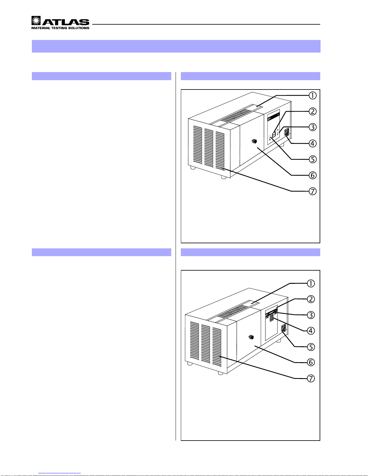
3.1 Description of Suntest CPS .......................................................................................................................10
3.2 Description of Suntest CPS+ .....................................................................................................................10
3.3 Components with similar construction SUNTEST CPS / CPS+ .................................................................. 11
4 Description offunctions ...............................................................................................................................12
4.1 Radiationand filtering.................................................................................................................................12
4.2 Ventilation circuits......................................................................................................................................12
4.3 Spectraldistributionwithadditionalfilters...................................................................................................13
4.4 Sensor system in SUNTEST CPS+ ...........................................................................................................14
4.5 Safetydevices ...........................................................................................................................................15
4.6 Safetymarkings.........................................................................................................................................15
5 Accessories ...................................................................................................................................................16
6 Commissioning .............................................................................................................................................18
6.1 Mountingofspecimentable .......................................................................................................................18
6.2 Assembling the radiation system ...............................................................................................................18
6.3 Connectiontopowersupply .......................................................................................................................21
7 Operation and shutdown .............................................................................................................................22
7.1 Configurationofunit ...................................................................................................................................22
7.2 Standardtestingprocedure ........................................................................................................................22
7.3 Testingprocedurewithoptionalunit............................................................................................................22
7.4 OperationofSUNTEST CPS ......................................................................................................................23
7.5 Operationof SUNTESTCPS+programcontroller......................................................................................23
7.6 Data transfer to a PC .................................................................................................................................24
7.7 Shutdown...................................................................................................................................................24
8 Calibration ....................................................................................................................................................25
8.1 Calibrationof irradiancewiththe XenoCalGlobalSensor ............................................................................25
8.2 Calibrationofirradiance with the RadialuxGlobalSensor ...........................................................................26
8.3 Calibrationoftheblack standardtemperature.............................................................................................27
9 Cleaning / Consumables..............................................................................................................................28
9.1 Cleaning.....................................................................................................................................................28
9.2 Consumables/ Spare parts........................................................................................................................29
10 Maintenance .................................................................................................................................................30
10.1 Maintenanceand care................................................................................................................................30
10.2 Commissioning ..........................................................................................................................................30
11 Technical data ..............................................................................................................................................31
Content Page

- 3 -
OperatingmanualSUNTESTCPS/CPS+
List of graphics Page
Fig. 1 Description of unit Suntest CPS.................................................................................................................10
Fig. 2 Description of unit Suntest CPS+...............................................................................................................10
Fig. 3 Components with similar construction SUNTEST CPS / CPS+ .................................................................. 11
Fig. 4 Testchamber .............................................................................................................................................11
Fig. 5 Radiationandfiltering.................................................................................................................................12
Fig. 6 Ventilation circuits......................................................................................................................................12
Spectraldistribution with additional filters...................................................................................................13
Fig. 7 Sensor system in the SUNTEST CPS+ .....................................................................................................14
Fig. 8 Safetydevices ...........................................................................................................................................15
Fig. 9 Safety markings.........................................................................................................................................15
Fig. 10 Mounting ofspecimen table .......................................................................................................................18
Fig. 11 Components ofthe radiation system ..........................................................................................................18
Fig. 12 Opening theassembly compartment..........................................................................................................19
Fig. 13 Installation ofoptical filters .........................................................................................................................19
Fig. 14 Installation of Xenon lamp..........................................................................................................................20
Fig. 15 Installation ofmirrors..................................................................................................................................20
Fig. 16 Closing theassembly compartment ...........................................................................................................21
Fig. 17 Connection topower supply .......................................................................................................................21
Fig. 18 Standard testingprocedure ........................................................................................................................22
Fig. 19 OperationofSUNTESTCPS ......................................................................................................................23
Fig. 20 Operation ofSUNTEST CPS+programcontroller .......................................................................................23
Fig. 21 Data transferto aPC (pinconfiguration) .....................................................................................................24
Fig. 22 Calibration ofirradiance withthe XenoCalGlobalSensor ............................................................................25
Fig. 23 Calibration ofirradiance withthe RadialuxGlobal Sensor ...........................................................................26
Fig. 24 Calibration ofthe blackstandard temperature.............................................................................................27

OperatingmanualSUNTESTCPS/CPS+
- 4 -
Dear user,
Please note that certain kinds of work must only be carried out by personnel who are suitably qualified:
• The SUNTEST CPS/CPS+ may be operated only by trained und authorized laboratory personnel,
• The unit should only be cleaned by trained personnel.
• Thisoperatingmanualdescribes the SUNTEST CPS and the SUNTEST CPS+ weathering units.
• PleasereadtheOperatingManualcarefullybeforeusingthe SUNTEST CPS/CPS+.
You will then be able to exploit all theadvantagesthat the device offersand prevent damage.
• Ifunusual problems occur, that have notbeentreated in sufficient detailin this operating manual, please contactthe
supplierfor your own safety.
1Notes for safe operation
ATLAS Material Testing Technology B.V
Vogelsbergstr. 22
63589 Linsengericht / Altenhaßlau
Deutschland
Phone ++ 49 / 6051 / 707-140
Fax ++ 49 / 6051 / 707-149

- 5 -
OperatingmanualSUNTESTCPS/CPS+
1Notes for safe operation
Dear User:
• Thisunit has been manufactured according to thestate-of-the-artand is operationally safe. Nonetheless, there may
besome danger from this unit, especially if itisoperated by personnel who are not adequately trained, orifit is used
inan improper manner, and not for its intended purpose.
• For personnel working with or on this unit, the operating agency must provide written instructions, in an easy-to-
understandform, based on these instructions, and make it available in the natural language of the employee (FRG:
Accident Prevention Act, UVV VGB 1 § 7, 2).
• Basedon these instructions, train the operating and cleaning personnel in the function, operation and maintenance
of this unit.
• The contents of this operating manual are subject to change at any time without prior notice.
• TheGerman version of this operating manual is binding in the case of translationsin other, foreign languages.
• For reasons of safety, changes or modifications to the unit on your own initiative are not permitted.
Please keep this operating manual carefully and accessibly in the vicinity of your instrument, so that safety
instructions and important information can be looked up at any time.
Trade marks:
All the trade marks in the instructions are the exclusive property of the respective manufacturers.
Copyright©
1999,ATLAS MTT BV • D-63589 Linsengericht-Altenhaßlau • Germany
Edition dated:
March1999

OperatingmanualSUNTESTCPS/CPS+
- 6 -
Safety symbols will draw your attention to safety-criti-
cal operating errors.
Symbols used in the operating manual
WARNING!
Non-compliance with these can result in serious or even
fatal injury.
CAUTION!
Non-compliance with these can result in medium to light
personalinjuryordamagetoproperty.
NOTE!
Providesusage tips and useful information.
CE - Conformance mark
Symbols on the unit
Pulloutthe power plug before opening the device !
Warnsyounottotouchlivepartsofthe unit when you open
thedevice.
CE - Conformance mark
1Notes for safe operation
1.1 Explanation of the pictorial signs
Pull mains plug
before opening !

- 7 -
OperatingmanualSUNTESTCPS/CPS+
1Notes for safe operation
Please also follow the safety instructions in the individual chapters.
Usage as authorized:
• SUNTESTCPS / CPS+ are used for exposure and weathering ofmaterial samples.
• Theunit is suitable for continuous operation.
• The unit has been tested for electromagnetic compatibility and for installation in an industrial application.
Unauthorized usage:
•No substances of materials that are inflammable or that can explode should be used in the test chamber.
• No substances or materials that may release toxic substances in any form should be used in the test chamber.
• Thedevice must notbeused for drying or heating objects or foodstuffs.
Safety instructions for commissioning:
WARNING - Pull out the power plug:
Coming in contact with live parts can result in a possibly fatal electrical shock. When assembling the irra-
diance system, set the ON (I) / OFF (O) switch to the "OFF (O)" position and pull out the power plug. Secure
the power plug from being inserted again.
WARNING - UV radiation being emitted:
If the specimen table is not used, UV radiation is emitted on the lower side of the unit and can result in
damage to skin and retina. Always use the specimen table when the unit is running !
WARNING - UV radiation being emitted:
If the mirrors (figure 15) are not used, UV radiation is emitted on the upper side of the unit and can result in
damage to skin and retina. Always mount the mirrors.
CAUTION - Danger of cuts and gashes:
The optical filters have sharp edges that may cause cuts and gashes.
Always wear protective gloves when working on the radiation system.
The device fulfills the following safety specifications:
• DINEN Part 1:1991-11, Part 2:1995-06
Safetyofmachinery
• DINEN 60601 Part 1:1994-05
Safety regulations for electrically operated measuring, controlling, regulating and laboratory equipment. General
requirements.
• DINEN 50178(VDE0160):1998-04
Electronicequipment for use in power installations
• DINEN 50082 (VDE 0839) Part 2:1997-11
Electromagnetic compatibility, Professional Basic Norm, immunity from distortion. Part 1: Residential areas, busi-
ness and industrial areas as well as small industries. Part 2: Industrial area.
Disposal:
• Please dispose of the packing materials according to the applicable disposal guidelines. There is a list given in
chapter 2.2, "Packing Material".
• Xenon lamps are special waste and may be sent toATLAS MTT B.V. for disposal.
• Old units contain re-usable materials. Therefore, please do not simply dispose of old units at the nearest garbage
dump, but ask your city or community administration for the possibilities of recycling.
1.2 Instructions for safe operation

OperatingmanualSUNTESTCPS/CPS+
- 8 -
2Installation of unit
2.1 Supply schedule
The weathering unit is available in two versions: SUN-
TEST CPS or SUNTEST CPS+.
Thebasicunit of SUNTESTCPS consists of:
• Xenonlamp,
• Optical filter "coated quartz filter segment",
• UVmirror and light mirror,
• Specimentable,
• Sensorfor measuring and regulating irradiance (E),
• Controlpanelwithrotaryswitchforinfinite adjustment
of irradiance, Xenon lamp operating hour meter and
switchforignitingtheXenon lamp.
• ON (I) / OFF (O) switch.
SUNTEST CPS+ is equipped with the following:
• Xenonlamp,
• Optical filter "coated quartz filter segment",
• UVmirror and light mirror,
• Specimentable,
• Sensorfor measurement and control of irradiance(E),
• Sensor formeasurement andcontrol of the blackstan-
dardtemperature (BST),
• Sensor for measuring the test chamber temperature
(TCT),
• Program controller with a display for displaying data
andkeyboardfor data input,
• ON (I) / OFF (O) switch,
• Serial RS 232-port for connection to a PC.
2.2 Packing material
• Polyethylenefoam (PE)
• Corrugatedcardboard

- 9 -
OperatingmanualSUNTESTCPS/CPS+
2.3 Location requirements
Climatic conditions required for the place of instal-
lation:
• Duringcontinuous operation, the hotairemitted by the
air-coolingsystem results in a constantly changing cli-
mateinthe room.Therefore,theSUNTESTunit should
onlybe installed in air-conditioned, sufficiently ventila-
ted places of installation.
• The places of installation must be kept free of dust.
• The room temperature must be maintained between
18°Cand 25°C.
• The max. relative humidity should be 70%.
The requirement for coolant air is as follows:
• 120m³/h forlampcooling andcoolingof thetestcham-
ber.
2Installation of unit
2.4 Installation
Installation SUNTEST CPS / CPS+:
• Dimensions of unit (width x depth x height):
780 mm x 350 mm x 350 mm,
• Weight of unit approx. 30 kg,
• Theunit must be set up on a sufficiently stable labora-
torybench with a non-flammable support underneath;
the laboratory bench should be aligned so that it is
horizontal.
Caution - Overheating of the unit:
Blocking of the air inlet and air outlets can result in
overheating and damage to the unit!
When installing the unit, the following minimum di-
stances to the neighboring walls or objects must be
maintained:
to the front: 700 mm
to the back: 500mm
to the top: 350mm
to both sides: 300mm

OperatingmanualSUNTESTCPS/CPS+
- 10 -
!Coveringhood
"Xenon lamp operatinghourmeter
#Rotary switch for setting the irradiance
$ON (I) / OFF (O) switch
%Switchfor igniting the Xenon lamp
&Test chamber door
'Airoutlet of the lamp cooling and temperature control
of the test chamber
Figure 1
3Description of unit
Figure 2
!Coveringhood
"Programcontroller
#Display
$Numericalkeyboard
%ON (I) / OFF (O) switch
&Test chamber door
'Airoutlet of the lamp cooling and temperature control
of the test chamber
3.1 Description of SUNTEST CPS
SUNTEST CPS facilitates manual setting of the testing
programs. The irradiance that has been set is regulated
at a constant value throughout the test duration.
Upper side of the unit:
• Covering hood !of the assembly compartment for
the lamp and filtering system.
Front side of the unit:
• Rotary switch #for setting the irradiance,
• Xenonlamp operating hour meter ",
• Switch%for igniting the Xenon lamp,
• ON (I) / OFF (O) switch $,
• Test chamber door &.
Left side of SUNTEST CPS:
• Air outlet 'of the lamp cooling and the temperature
control of the test chamber.
3.2 Description of SUNTEST CPS+
SUNTEST CPS+ is equipped with a microprocessor-ba-
sedcontroller for measurement and regulation and works
withsoftware-controlled testing programs.
Upper side of the unit:
• Covering hood !of the assembly compartment for
the lamp and filtering system.
Front side of SUNTEST CPS+:
• Program controller "with
• Numeric keypad $and
• Display #,
• ON (I) / OFF (O) switch %,
• Test chamber door &.
Left side of SUNTEST CPS+:
• Air outlet '(
of the lamp cooling and the temperature
regulationof the test chamber.

- 11 -
OperatingmanualSUNTESTCPS/CPS+
3Description of unit
Figure 3
!RS 232 port
"Portforconnectingtheoptionalcooling/immersionde-
vice
#Air inlet opening for lamp cooling and temperature
regulationof the test chamber
$Power plug with connecting cable
%Air outlet of the lamp cooling and the temperature
regulationof the test chamber
Figure 4
!Door lock switch
"Test chamber door
#Reflector
$Photodiodefor measuring irradiance
%Air inlet for temperature regulation in the testing
chamber
&Black standard sensor (BST sensor)
'Specimen table
Test chamber: Fig. 4
• Doorlock switch !foropening / closingthetest cham-
ber door ".
• The reflector #is located in the test chamber and in
the test chamber door. The Xenon lamp is located in
the roof of the test chamber.
• The photodiode $measures the irradiance E,
• The black standard sensor (BST sensor) &(only in
CPS+) measures the black standard temperature at
thespecimen level.
• Air inlet %for temperature control in the test
chamber.
• The specimen table 'isused for positioning the spe-
cimens.
3.3 Components with similar construction
SUNTEST CPS / CPS+ Figures 3 / 4
The rear sides of the units and the test chambers are
similar in design in both models.
Rear side of the unit: Fig. 3
• Air inlet opening #for the Xenon lamp cooling and
thetemperatureregulation of the test chamber,
• Port "for connecting the optional cooling device or
immersiondevice (only SUNTESTCPS+),
• RS 232 port for data transfer to a PC (only SUNTEST
CPS+),
• Power plug with connecting cable $,
• Air outlet %of the lamp cooling and the temperature
regulationof the test chamber.

OperatingmanualSUNTESTCPS/CPS+
- 12 -
• The specimens &are placed on the specimen table
%. Radiation $is generated with a Xenon lamp #
and filtered through an optical filter "coated quartz fil-
ter segment" ".
NOTE:
There are optional optical filters (see Chapter 5 "Acces-
sories") available for various spectral distributions (see
chapter. 4.3, "Spectraldistributionwithadditionalfilters").
• The UV component of the radiation that is directed
upwards is reflected on the specimens &by the mir-
rors!placed above the Xenon lamp #.
• Thecomponentsofthenon-dangerousIRradiation(heat
radiation) might penetrate through the mirrors. The
remaining heat is removed out of the unit via the air
circuitof the Xenon lamp.
4Description of functions
Figure 5
!Coolantair supply Xenon lamp and
regulationof test chamber temperature
"Coolantair outlet Xenon lamp and
regulationof test chamber temperature
4.1 Radiation and Filtering
4.2 Ventilation circuits
• The coolant air of the Xenon lamp and the test cham-
ber !is aspirated on the rear side of the unit (see
chapter 3.3, "Rear side of unit") through an air filter,
flowsthrough thetest chamber andthe assemblycom-
partment of the irradiance unit and exits through the
exhaust openings "(at the left and the rear side of
the unit (see chapter 3.3, "Rear side of unit").
NOTE:
Duringcontinuous operation, the hot air emittedbythe air
cooling system results in a continuous change in the cli-
mateinside the chamber.
Figure 6
!Mirrors (UV and light mirrors)
"Optical filter "coated quartz filter segment"
#Xenonlamp
$Radiation
%Specimen table
&Specimens

- 13 -
OperatingmanualSUNTESTCPS/CPS+
4Description of functions
4.3 Spectraldistributionwithadditionalfilters Figures: Spectra
0
0,5
1
1,5
2
2,5
3
250 300 350 400 450 500
Wavelength (nm)
Irradiance [W/(m²xnm)]
UV MAX
UV special glass
Special window glass
SUNTEST CPS/CPS+
E(300nm-800nm) = 765W/m²
0
1
2
3
4
5
6
200 300 400 500 600 700 800 900
Wavelength (nm)
Irradiance [W/(m²xnm)]
UV special glass
CIE85 (Table 4)
SUNTEST CPS/CPS+
E(300nm-800nm) = 765W/m²

OperatingmanualSUNTESTCPS/CPS+
- 14 -
4Description of functions
4.4 Sensor system in SUNTEST CPS+
SUNTEST CPS+ has integrated sensors:
• Sensor for measuring the global irradiance (E) in the
rangeof 300- 800 nmand for regulationin the rangeof
250 -765 W/m²,
• Sensor for measuring and regulating the black stan-
dardtemperature(BST)up to about 100 °C,
• Sensor for measuring the test chamber temperature
(TCT).
Irradiance (E):
• Duringtesting, irradianceis measured bya photodiode
!and regulated electronically to achieve a constant
value.
Black Standard Temperature (BST)
• During testing the black standard sensor (BST sen-
sor)"continuously measures the temperature.
• Theblack standard temperature(BST) is regulated via
the speed of the test chamber ventilator.
Test chamber temperature (TCT):
• Thetest chambertemperature(TCT) ismeasuredby a
temperature sensor in the exhaust air flow of the test
chamber.
• The test chamber temperature cannot be controlled
andis indicated in the display unit of the program con-
troller.
Measurement data:
• The measurement data can be transferred, with the
testing program running, via the RS 232-port at the
rear side of the unit to a PC or a printer with a serial
interface.
!Photodiodefor measuring irradiance
"Black standard sensor (BST sensor)
Figure 7

- 15 -
OperatingmanualSUNTESTCPS/CPS+
!ON (I) / OFF (O) switch
"Door switch for test chamber door
#Safety switch for lamp replacement
$Temperaturesafety device
4Description of functions
Figure 8
4.5 Safety devices
There are safety and protection devices that increa-
se the operational and functional safety of the unit:
• To switch off the unit in an emergency, set the ON (I) /
OFF (0) switch !to position "OFF (0)".
• Adoor switchswitchesoff the unitwhen the testcham-
ber door "is opened.
• A safety switch interrupts the power supply when the
covering hood #of the assembly compartment is re-
moved.
• A temperature safety device $switches off the unit if
thereis adanger ofthe Xenonlampgetting overheated
becauseofinsufficientcooling.
Figure 9
4.6 Safety markings
Please check whether the safety markings mentio-
ned below have been put on the unit.
If any of the safety markings is absent, please inform
your supplier.
• The safety marking "Pull out power plug before ope-
ning the device!" !on the rear side of the unit warns
you not to touch live parts of the unit when you open
thedevice.
!Pull out mains plug
Pull out mains plug be-
fore opening the device!

OperatingmanualSUNTESTCPS/CPS+
- 16 -
5Accessories
Item Accessories Description Ident no.:
1Sensors:
1.1 XenoCal UV sensor Measurement of irradiance
Measurement range 300 - 400 nm 5500 7270
1.2 XenoCal global sensor Measurement and calibration of irradiance
Measurement range 300 - 800 nm 5500 7271
1.3 Adapter table for XenoCal sensors Holding plate for insertion of the XenoCal sensor
in the testing chamber 5507 7745
1.4 Black standard sensor (BST sensor) Measurement of the black standard temperature
(BST) 5500 1490
1.5 White standard sensor (WST sensor) Measurement of the white standard temperature
(WST) 5500 1491
1.6 Sensor WST set Measurement of the white standard temperature
(WST), separate readout device is necessary 5507 7906
1.7 Adapter table for BST and WST
or Radialux sensors Holding plate for inserting the SST and WST or
Radialux sensors in the testing chamber 5605 2825
1.8 XENOVIEW, serial 9-pole Software package for transferring the test
parameters to a PC 5507 6813
1.9 XENOVIEW, serial 25-pole Software package for transferring the test
parameters to a PC 5507 6812
2 Filters:
2.1 UV special glass In addition to the coated quartz disk for working
with wavelengths greater than 290 nm 5605 2371
2.2 Special window glass In addition to the coated quartz disk for working
with wavelengths greater than 310 nm 5605 2372
2.3 Solar standard Filter according to COLIPA and DIN 67501 5607 7759
2.4 Solar ID65 Filter for light exposure according to the ICH
guideline (only in combination with 5605 2372) 5607 7769
2.5 Uncoated quartz disk Instead of the coated quartz disk for higher
black standard temperatures 5605 2373
3 Testing table
3.1 Water-cooled testing table
(contact cooling) For light exposure of temperature-sensitive
materials 5605 2389
4 Covering sheets
4.1 Set of covering sheets Covering sheets for direct visual comparison of
the weathered and unweathered test areas 5606 0361

- 17 -
OperatingmanualSUNTESTCPS/CPS+
5Accessories

OperatingmanualSUNTESTCPS/CPS+
- 18 -
6Commissioning
6.1 Mounting of specimen table
WARNING - UV radiation being emitted:
If the specimen table is not used, UV radiation is emit-
ted on the lower side of the unit and can result in
damage to skin and retina.
Always use the specimen table when the unit is run-
ning!
1. Use handle !to open the test chamber door ".
2. Mount the specimen table $.
NOTE:
For reproduction and comparison of testings, the BST
sensor should always be placed at the same location of
the specimen table.
3. Place the black standard sensor #on the specimen
table $.
Figure 10
!Handle
"Test chamber door
#Black standard sensor
$Testing table
!Optical filter "coated quartz filter segment"
"Optionalopticaladditionalfilter
#Xenonlamp,
$UVmirror (transparent)
%Lightreflector (mirror coating)
Figure 11
6.2.1 Components of the irradiance system
Theradiationsystemis packedseparately. Please check
the components for damage before assembly. Damaged
parts must not be installed.
The radiation system consists of:
!the optical filter "coated quartz filter segment"
(optional:uncoatedquartzfiltersegment),
"theoptional optical additional filters
(see chapter 5, "Accessories"),
#theXenon lamp
$theUV mirror (transparent), pre-mounted, with
%thelightmirror(mirror coating).
NOTE:
When assembling the optical filter, put the quartz filter
segment(coated or optionallyuncoated)and then thesel-
ected optional additional filter in place.
6.2 Assembling the radiation system
The specimen table and the radiation system need to be
assembled before the unit can be commissioned.
CAUTION - Danger of burns:
For cooling the hot radiation system, the fan conti-
nues to run even after the unit has been switched
off.
Open the test chamber only after the fan has auto-
matically switched off.

- 19 -
OperatingmanualSUNTESTCPS/CPS+
!Recessed head screws 2x
"Coveringhoodof the radiation system
#Assembly compartment
Figure 12
6Commissioning
6.2.2 Opening of assembly compartment
WARNING - Pull out the power plug:
Coming in contact with live parts can result in
a possibly fatal electrical shock.
When installing the irradiance system, set the
ON (I) / OFF (O) switch to the "OFF (O)" position
and pull out the power plug.
Secure the power plug from being inserted
again.
1. SettheON (I)/ OFF(0)switchtothe "OFF(0)"position.
Pull the plug out of the socket.
Secureit against being inserted again.
2. Loosen the two recessed head screws !with a
screwdriver.
3. Removethe covering hood "ofthe irradiance system
upwards and put it aside.
4. The assembly compartment #is now freely accessi-
ble.
!Coated / optional uncoated quartz filter segment
"Holding frame in the assembly compartment
#Optionaladditional filter
Figure 13
6.2.3 Installation of optical filters
Cleanthe optical filters before assembling with a soft lea-
ther cloth / brush. Carefully wipe the optional filter "UV
special glass" with a starch-free cloth that is moistened
with 20 % citric acid solution.
CAUTION - Danger of cuts and gashes:
The optical filters have sharp edges that may cause
cuts and gashes.
Always wear protective gloves when working on the
radiation system.
NOTE:
Theholding frame in which the optical filters are placed is
located in the assembly compartment.
1. Puton protective gloves.
2. First place the optical filter "coated quartz filter seg-
ment" or the optional "uncoated quartz filter segment"
!in the holding frame "(in the assembly compart-
ment.
3. Then position the optional optical filters #(see chap-
ter 5, "Accessories").

OperatingmanualSUNTESTCPS/CPS+
- 20 -
6Commissioning
!Xenonlamp
"Lamp socket 2x
#Flat connector 2x
$Plug-in contact 2x
%Mounting 2x
Figure 14
!Retaining clip
"Lightmirror (mirror coating)
#UVmirror (transparent)
$Holes for retaining clips
%Mirrorsupport
Figure 15
6.2.5 Installation of the mirrors
WARNING - UV radiation being emitted:
If the mirrors (figure 15) are not used, UV radiation is
emitted on the upper side of the unit and can result
in damage to skin and retina. Always mount the mir-
rors.
NOTE!
Themirrors arepre-mounted. Whencleaning orreplacing,
install the mirrors in the sequence described.
Cleanthe mirrors with asoft leather clothorabrushbefore
installation.
1. First, place the transparent UV mirrors #in the sup-
port %.
2. Then position the light mirror ".
3. Fix the mirrors in the holes $by inserting the two
retaining clips !.
4. Insert the mirror support %with components fitted into
theradiationcompartment.
6.2.4 Installation of the Xenon lamp
Beforeinstallation,theXenonlampshouldbecleanedwith
a starch-free cloth that is moistened with a small amount
of spirit.
NOTE!
Thelamp holder is located in the assembly compartment.
1. Carefully press the Xenon lamp !at the lamp sok-
kets "into the mounting %.
2. Insert the flat connector #into the plug-in contact $.
This manual suits for next models
1
Table of contents
Other Atlas Laboratory Equipment manuals
Popular Laboratory Equipment manuals by other brands

Enapter
Enapter EL 2.1 owner's manual

LAN Power
LAN Power LP-2124 installation guide

VWR
VWR Mini Shaker Series instruction manual

Agilent Technologies
Agilent Technologies 1260 Infinity VL user manual

Sartorius
Sartorius Picus 2 operating instructions

Inficon
Inficon LDS3000 AQ Translation of the original operating instructions