PennEngineering • www.pemnet.com
9
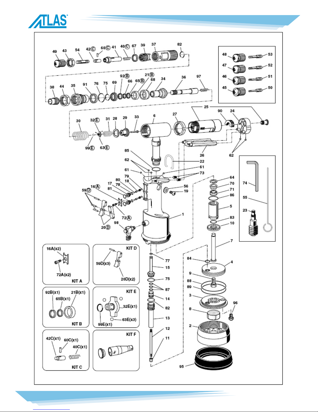
SPARE PARTS - METRIC TOOL
NO. CODE QTY. DESCRIPTION
01 721779 1 Toolbody
02 712269 1 Bodycover
03 711684 1 Cylinderbottom
04 721685 1 Pneumaticpiston
05 711780 1 Connector
06 721689 1 Oleodynamiccylinder
07 711781 1 Stem
08 711691 1 Silencer
09 711692 1 ScrewM7x1
10 711782 1 Dampener
11 711694 1 Lowercoil
12 711695 1 Threadedsleeve
13 721698 1 Valvebody
14 711700 1 Uppercoil
15 711701 1 Uppervalvebody
16A 711702 1 Plate
17 711703 2 Valvebody
18 711704 2 Valvepiston
19 710839 1 Oiltankplug
20D 711705 2 Push-button
21B 711713 1 Spacer
22 710854 1 Balancerhook
23 721387 1 Oilcontainer
24 711783 1 Motorcover
25 720024 1 MotorF002
26 711785 1 Motorprotectionsector
27 711786 1 Ringnutformotor
28 711787 1 Stopring
29 712670 1 Clutch
30 711790 1 Pistonreturnspring
31 711791 1 Balllockingspring
32E 711792 1 Ballbushing
33 712270 1 Rod
34 711794 1 OleodynamicPiston
35 711795 1 Frontconnector
36 711796 1 Shaft
37 711797 1 Milledsleeve
38 711798 1 Strokeadjustingnut
39 711799 1 Strokeadjustingknob
40C 711800 1 Springdisengagementtierod
41 711801 1 Headcarryingtierod
42C 711802 1 Clutchfortierod
43 711803 1 Headringnut
44 711804 1 Ringnut
45 711805 1 HeadM3
46 711806 1 HeadM4
47 711807 1 HeadM5
48 711808 1 HeadM6
49 711809 1 HeadM8
50 711810 1 TierodM3
51 711811 1 TierodM4
52 711812 1 TierodM5
53 711813 1 TierodM6
54 711814 1 TierodM8
55 710876 1 Pindisengagementtierod
56 710906 1 Hermeticwasher400-820
59D 711726 3 Pin2x20UNI1707
60C 710537 1 Springpin4x12
61 711815 2 Ballø3.5
62 710911 4 Ballø4
63E 711816 3 Ballø2.5
64 711817 1 SeegerringI18
65B 710902 1 SeegerringE16
66 711818 1 SeegerringSW11x1
67 711821 1 SeegerringJV20x1
68 711721 1 BalseleB-110078/B/NEO
69 711722 1 BalseleB-094063/B/NEI
70 711819 1 BalseleB-070039/1
71 711820 1 GasketTS-10-18-5.8/L
72A 711727 1 ScrewVSP-4x8UNI5933
73 712037 2 Inoxlterø6x4
74 711092 1 Keymm5
75 711728 2 ORing-2-16P
76 711730 1 ORing-2-119(N552/90)P
77 710367 1 ORing-2-8P