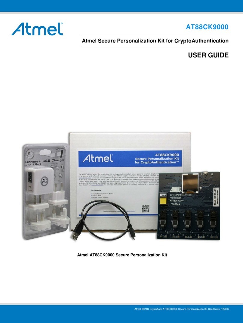
Atmel AT88SC-DK1 User manual
Other Atmel Security System manuals
Popular Security System manuals by other brands

Inner Range
Inner Range Concept 2000 user manual

Climax
Climax Mobile Lite R32 Installer's guide

FBII
FBII XL-31 Series installation instructions

Johnson Controls
Johnson Controls PENN Connected PC10 Install and Commissioning Guide

Aeotec
Aeotec Siren Gen5 quick start guide

IDEAL
IDEAL Accenta Engineering information

Swann
Swann SW-P-MC2 Specifications

Ecolink
Ecolink Siren+Chime user manual

Digital Monitoring Products
Digital Monitoring Products XR150 user guide

EDM
EDM Solution 6+6 Wireless-AE installation manual

Siren
Siren LED GSM operating manual

Detection Systems
Detection Systems 7090i Installation and programming manual


