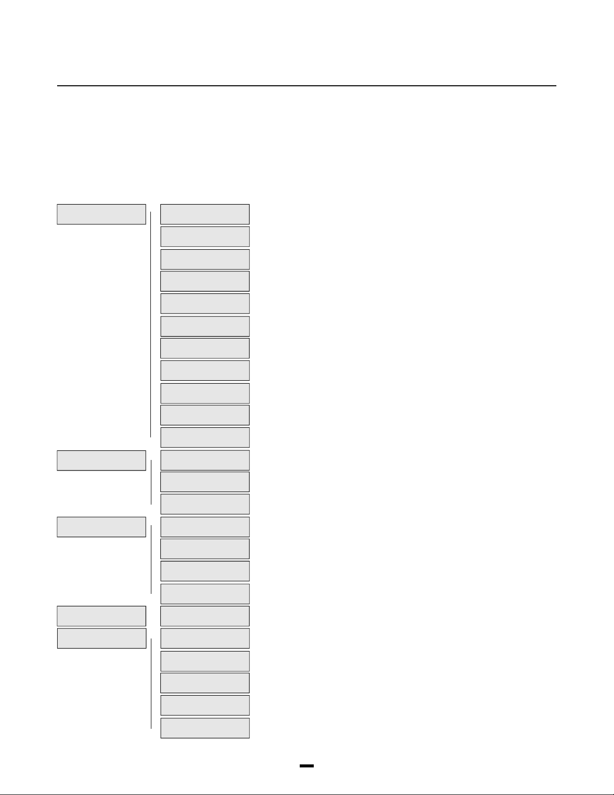
DSC PC 4010 Owner's manual

PC4O1O Software Version 2.1
Book 2
Programming Manual

1
Table of Contents
Programming the PC4010
Programming Toggle Options ________________________________________________________ 2
Programming HEX Digits ____________________________________________________________ 2
Programming Manual ___________________________________________________________3
Installer options _______________________________________________________________4
Event Messages _______________________________________________________________5
System Options
System Toggle Options _____________________________________________________________ 7
Keypad Toggle Options ____________________________________________________________ 11
Keypad Lockout Options ___________________________________________________________ 12
System Times _____________________________________________________________________ 12
Zone Supervision _________________________________________________________________ 12
Download Section
Download Toggles ________________________________________________________________ 13
DLS Options ______________________________________________________________________ 14
Communicator Section
Main Items - Phone Numbers/Communication Format/Dialer Direction ___________________ 15
Communicator Toggles ____________________________________________________________ 24
Communicator Miscellaneous ______________________________________________________ 27
Test Code Transmission ___________________________________________________________ 27
Reporting Codes __________________________________________________________________ 27
Links Module _____________________________________________________________________ 32
Switched Auxiliary Output ______________________________________________________34
Main Bell Output ______________________________________________________________35
PGM Outputs
Main PGM Output _________________________________________________________________ 36
PC4204 Options __________________________________________________________________ 36
PC4216 Options __________________________________________________________________ 36
PC4216 Custom___________________________________________________________________ 37
Escort4580 Automation Items _______________________________________________________ 37
PGM Pulse Times _________________________________________________________________ 37
PGM Outputs List _____________________________________________________________38
PC4400 Options ______________________________________________________________41
System Label_________________________________________________________________44
Event Scheduling _____________________________________________________________45
Add / Edit Partitions
Partition Toggles __________________________________________________________________ 49
Partition Times ____________________________________________________________________ 51
Zone Assignment _________________________________________________________________ 52
Zone Type________________________________________________________________________ 52
Zone Options _____________________________________________________________________ 55
Partition Label ____________________________________________________________________ 55
Delete/Copy Partition __________________________________________________________56
Module Hardware
Enroll Module _____________________________________________________________________ 57
Delete Module ____________________________________________________________________ 58
Confirm Module ___________________________________________________________________ 58
RF Zone Options __________________________________________________________________ 58
RF Zones - Summary ______________________________________________________________ 60
Event Buffer _________________________________________________________________61
Diagnostics __________________________________________________________________62
Appendix A
List of Available ASCII Characters ___________________________________________________ 63
Appendix B
List of Diagnostics_________________________________________________________________ 64

2
PROGRAMMING
THE PC4010
The PC4010 incorporates a new method of programming which uses a menu system to find a specific program location
when it is to be entered.
Book 3 contains the programming flow charts for the PC4010. The charts are arranged in such a way as to allow you to
quickly find any option and the path required to arrive at the program location. In addition you will be able to see other
options also available to you in the program area.
Plain boxes are program areas and shaded boxes are menu selections.
Two methods may be used to select the different menu items to arrive at a program location. With the first, you may use
the arrow keys (< >) to scroll through the menu items. When the desired item is displayed press the [Q] key. The [Q] key
is used as an ‘ENTER’ or ‘SELECT’ key. The panel will then move you to the next set of options.
The other method incorporates a ‘HOTKEY’ system. Every menu and program item contains a one or two digit ‘HOTKEY’
entry. Simply press the number(s) in the menu or program box and the panel will automatically select the item for you.
DO NOT PRESS THE [Q] AFTER ENTERING THE ‘HOTKEY’ NUMBER. This second method is much quicker once you
become familiar with it.
EXAMPLE: We wish to program the Exit Delay for Partition 4. The following is the flow chart located in Book 3.
SYSTEM AREA Scroll to desired option using
(0) the [<][>] keys and press [Q].
Ô
PARTITION AREA þADD/EDIT PAR þWHICH PARTITION þCUSTOMER ID CODE
(1) (0) (1) Ô(4) (0)
þPAR TOGGLES
(1)
þPARTITION TIMES þENTRY DELAY
(2) (0)
þEXIT DELAY
(1)
Using the first method the arrow keys would have to be pressed many times to scroll to the various items followed by the
[Q] key to select the item. Twelve keystrokes would be required after entering Installer Programming providing no
mistakes are made. The keystrokes required are as follows:
[>], [Q]to select PARTITION AREA [>], [>], [Q]to select PARTITION TIMES
[Q]to select ADD/EDIT PAR [>], [Q]to select EXIT DELAY
[>], [>], [>], [Q]to select to PARTITION 4
Using the second ‘HOTKEY’ method we require only 5 keystrokes:
[1] to select PARTITION AREA [2] to select PARTITION TIMES
[0] to select ADD/EDIT PAR [1] to select EXIT DELAY
[4] to select PARTITION 4
With less keystrokes required, programming is quicker as there is less chance of an error occurring.
At any time you may press the [#] key to exit a section. ANY DATA ENTERED WILL BE CHANGED. THE [#] KEY IS NOT
AN ABORT KEY! The [#] key can also be pressed to move you back to the previous menu. Pressing the [#] key several
times will exit you from Installer Programming.
To make programming easier the INDEX at the back of the Programming Manual includes the chart number beside every
option as well as the page number for a description of the option.
Programming Toggle Options
Some program areas contain several toggle options which pertain to the menu item selected. Use the arrow keys (<>) to
scroll through the various items. Press the [Q] key to toggle between [Y]es and [N]o for each feature. Once all the toggle
options have been programmed press the [#] key to save your changes and return to the previous menu.
Programming HEX Digits
Often HEX digits are required for a program item. When a HEX digit is required press the [Q] key to enter the HEX menu.
You may use the arrow keys to scroll through the HEX digits (A through F) and when the desired letter is displayed press
the [Q] key.
Another much quicker method for entering HEX digits is to, first, press the [Q] key followed by the number corresponding
to the HEX letter i.e. A = 1, B = 2, C = 3, up to F = 6. The [Q] key must be pressed before entering each HEX digit as the
software returns you to decimal programming automatically after each entry.
EXAMPLE: To enter data ‘ABCD’ on a PC4010 you would enter:
[Q], [1], [Q], [2], [Q], [3], [Q], [4]
Note: The [Q] key is required before every HEX digit entered.

3
PROGRAMMING
MANUAL
The PC4010 Installer’s Programming is broken down into 5 major sections:
System Area For programming options which affect the operation of the entire system. For example communications,
downloading, printer options etc. are options which affect the overall system and are programmed in the system area.
Partition Area For programming options which pertain to individual partitions. For example the zone assignment, entry
delay time and exit delay time are all options which can be programmed for each of the partitions.
Module Hardware For enrolling and deleting modules.
Event Buffer For the installer to reprint the entire event buffer.
Diagnostics For viewing trouble conditions reported by the modules. Page
SYSTEM AREA þINSTALLER OPT’S __________________________________________ 4
(0) (00)
þEVENT MESSAGES __________________________________________ 5
(01)
þSYSTEM OPTIONS __________________________________________ 7
(02)
þDLS SECTION __________________________________________ 13
(03)
þCOMMUNICATOR __________________________________________ 15
(04)
þSW AUX OUTPUT __________________________________________ 34
(05)
þMAIN BELL OUTPUT __________________________________________ 35
(06)
þPGM OUTPUTS __________________________________________ 36
(07)
þPC4400 OPTIONS __________________________________________ 41
(08)
þSYSTEM LABEL __________________________________________ 44
(09)
þEVENT SCHEDULING __________________________________________ 45
(10)
PARTITION AREA þADD/EDIT PAR __________________________________________ 49
(1) (0)
þDELETE PARTITION __________________________________________ 56
(1)
þCOPY PARTITION __________________________________________ 56
(2)
MODULE HARDWARE þENROLL MODULE __________________________________________ 57
(2) (0)
þDELETE MODULE __________________________________________ 58
(1)
þCONFIRM MODULE __________________________________________ 58
(2)
þRF ZONE OPTIONS __________________________________________ 58
(3)
EVENT BUFFER þPRN ENTIRE BUFF __________________________________________ 61
(3) (0)
DIAGNOSTICS þDIAGNOSTICS __________________________________________ 62
(4) (0)
þBINARY PROGRAM __________________________________________ 62
(1)
þMEMORIZE VBAT __________________________________________ 62
(2)
þFACTORY DEFAULT __________________________________________ 62
(3)
þDEFAULT 4580 __________________________________________ 62
(4)

4
INSTALLER
OPTIONS
SYSTEM AREA INSTALLER OPTS
This section contains the Installer’s Code, Grand Master Code, 2nd Grand Master Code, Walk
Test Code and Installer’s Lockout options.
Program Installer’s Code. A new Installer’s Code can be programmed. The default setting is
‘4010’ for 4 digit option, or ‘401000’ for 6 digit option. Enter a new 4 digit code using numbers
from 0 to 9 only. The installer’s code is used to enter [Q][8] Installer’s Programming Commands.
This code should be changed from the default setting before programming is complete to ensure
the security of the system.
Note: If the installer’s code is lost, and installer’s lockout is enabled, there is no way to
enter installer’s programming. The panel will have to return to DSC. Panels returned to DSC
with the installer’s lockout feature enabled and no other apparent problems will be subject
to an additional service charge.
Program Grand Master Code. Master code 001 is the System Grand Master Code. This is the only
code which can program other system master codes. The default setting of this code is ‘1234’ for
4 digit option, or ‘123456’ for 6 digit option. This code should be changed from the default setting
once programming is complete to ensure the security of the system.
The Installer may program a second System Grand Master Code which has the same access as
the System Grand Master Code 001. The Second Master Code is not one of the programmable
128 access codes in [Q][5] programming and therefore cannot be changed by the user. This
code may be used as a Master Key for service and trades people. The default setting of this
code is ‘AAAA’ for 4 digit option, or ‘AAAA00’ for 6 digit option.
PGM Walk Test Code allows access to the Walk Test Mode [Q] [6] [Walk Test Code]. The walk
test mode allows testing of zones that walk test is enabled on.
Each partition to be involved in the walk test must have [Q] [6] [Walk Test Code] entered on one
of its keypads.
Installer’s Lockout prevents the installer’s code and downloading access code from being
returned to their default values when a hardware or software default occurs.
Note: Panels returned to DSC with the installer’s lockout feature enabled and no other
apparent problems will be subject to an additional service charge.
Selecting this section will enable Installer’s Lockout and display the message “Ins Lockout
Enabled”.
Selecting this section will disable Installer’s Lockout and display the message “Ins Lockout
Disabled”.
INSTALLER OPTS
(00)
PGM INST CODE
(0)
PGM GRAND MASTER
(1)
PGM 2ND MAS CODE
(2)
PGM WALK TEST CD
(3)
INS LOCKOUT OPTS
(4)
ENABLE LOCKOUT
(0)
DISABLE LOCKOUT
(1)

5
EVENT
MESSAGES
SYSTEM AREA EVENT MESSAGES
Event messages are two custom messages programmed by the installer. These messages will be
displayed on the keypad when the user fails to arm or an alarm occurs while the system was
armed.
A cursor will appear under the first character of the label. The cursor can be moved to left or right
using the [<][>] keys. The letters of the alphabet have been divided up among the 1-9 number
keys on the keypad.
[1] = A, B, C, 1 [2] = D, E, F, 2 [3] = G, H, I, 3 [4] = J, K, L, 4 [5] = M, N, O, 5
[6] = P, Q, R, 6 [7] = S, T, U, 7 [8] = V, W, X, 8 [9] = Y, Z, 9, 0 [0] = Space
For example, if you press the [4] key, the letter ‘J’ will appear above the cursor on the display.
Press the [4] key again, the letter ‘K’ will appear above the cursor. Press the [4] key a third time
and the letter ‘L’ will appear above the cursor. Press it again and the number ‘4’ will appear on
the display. If a different key is pressed, for example the [6] key, the cursor will automatically
move to the right one space, and the letter ‘P’ will be displayed. To erase a character, move the
cursor under the character using the [<][>] keys, and press the [0] key.
While programming the zone label, press the [Q] key to call up an options menu. To select an
option, either press the corresponding number key, or toggle through the options using the [<][>]
keys and press the [Q] key to select.
[0] Clear Display [1] Clear to End [2] Change Case [3] ASCII Entry (See appendix A)
[4] Save
[0] Clear Display will clear the entire zone label.
[1] Clear to End will clear the display from the character where the cursor was located to the end of
the display.
[2] Change Case will toggle the letter entry between upper case letters (ABC...) and lower case
letters (abc...).
[3] ASCII Entry is for entering uncommon characters. There are 255 characters, but 000 to 031
are not used. Use the [<] [>] keys to toggle through the characters or enter a 3 digit number from
032 to 255. Press the [Q] key to enter the character into the zone label (see Appendix A for the
ASCII characters chart).
[4] Save the label programmed and return to the previous menu.
See [Q][6][Master Code][6] User Functions in the System Manual for enabling these messages
on each partition.
The “System Has Failed To Arm” message will appear on every keypad on a partition when a
valid code is entered but the system is unable to arm because a zone is not secure.
The message will clear after 5 seconds.
This message can be used to remind the user to check all zones and make sure they are secure
before attempting to arm the system.
The “Alarm Occurred While Armed” message appears when a partition is disarmed after an alarm
has occurred. The message will be displayed on all keypads on the partition being disarmed. The
message will clear after 5 seconds and display the zone(s) that went into alarm.
This message can be used to remind the users of what to do in their situation.
The third message is “Fire Alarm !!! 2 Wire Smoke”, this message will only be displayed if the 2
wire smoke detector on the PC4700 fire module goes into alarm.
The fourth message is “Fire Alarm !!! Waterflow Sensor”, this message will be displayed if the
waterflow detector on the PC4700 fire module goes into alarm.
Note: If there is more than one of these fire messages to be displayed at once the messages
will scroll one every three seconds to the next message. Once any fire alarm has been
silenced a message “Fire Bell Has Been Silenced” will be displayed on the partition and
global keypads until the partition is armed.
EVENT MESSAGES
(01)
FAIL TO ARM
(0)
ALARM WHEN ARMED
(1)
SMOKE DETECTOR
(2)
WATERFLOW ZONE
(3)

6
SYSTEM AREA EVENT MESSAGES
ZONE TAMPER
(6)
ZONE FAULT
(7)
SENSOR RESET
(4)
UTILITY OUTPUT
(5)
This message will be displayed for the sensor reset option in the [Q] menu. This message will
also be displayed when a sensor reset is performed.
This message will be displayed for the utility output option in the [Q] menu. This message will also
be displayed when a utility output is performed.
Notes: Since editing this label will affect how the Utility Output and Sensor Reset labels appear on all partitions if
the outputs perform different functions on different partitions the labels should be left at default.
The logs to the viewable and printed event buffer will not use the programmable label. They will continue to log as
“Utility Output” and “Sensor Reset”.
The “Zone Tamper” message will appear on every partition keypad when a zone using double EOL
is put into the tamper condition (zone open). The message is displayed while viewing open zones.
The “Zone Fault” message will appear on every partition keypad when a zone using double EOL is
put into the fault condition (zone shorted). The message is displayed while viewing open zones.
Note: Zone Tamper and Zone Fault sections will only appear when double EOL is being used.

7
SYSTEM
OPTIONS
SYSTEM AREA SYSTEM OPTIONS SYS TOGGLE OPT
This section contains options that are relevant to the entire system. System Toggle options,
Keypad Toggle options, Keypad Lockout options and System Time can all be programmed in this
section.
Sys Toggle Options
Toggle options are in question form. Use the [Q] key to toggle between Yes and No to enable or
disable the feature. Use the [<] [>] keys to scroll through the options.
Changeable System Grand Master Code?
YES =System Grand Master Code can be changed by the end user via Grand Master Code.
NO =The System Grand Master Code can only be changed via installer’s programming.
Shunt Zones on Power Up?
YES =All zones are considered non-violated by the main control for the first 2 minutes that
power has been applied to the system. This will allow time for the detectors to “settle”
without causing false alarms.
NO =The zones are active upon power up.
AC Trouble Displayed?
YES =The system will monitor and display an incoming AC power failure from the transformer.
NO =The system will not display the incoming AC power failures.
Is the incoming AC Frequency 60 Hz?
YES = The incoming AC power from the transformer cycles at 60 Hz. The North American
standard is 60 Hz.
NO =The incoming AC power cycles at 50 Hz.
AC inhibits arming?
YES =When an ACtrouble condition is present on the main panel or PC4204, the system cannot be
armed, except by autoarm.
NO =Regardless of the presence of an AC Trouble, the system can be armed.
DC inhibits arming?
YES =When a low battery condition is present on the main control panel or on a PC4204
expansion module, the system can not be armed (DC Inhibit Arm does not apply to
wireless zone that have battery troubles). If the partition is attempted to be armed the
keypad display will show the message “Fail To Arm... DC Trouble”. When an access code
is entered the panel will perform a battery check on the main control panel and on each of
the PC4204’s enrolled on the system. This will ensure that the battery condition is good
before the panel is armed. If the control panel has a battery trouble or any one of the
PC4204’s report back with a battery trouble the arming will be aborted.
No =No forced battery check will be performed and a Battery trouble will not inhibit arming.
Note: The Control panel and each of the PC4204 modules may only have 3 battery trouble
alarms in a 24 hour period. After the third battery trouble for a given module the trouble
condition will “Shutdown” until midnight of that day. The trouble will still be enunciated
with the keypad Trouble LED but the event will not be logged to the event buffer or be
communicated.
SYSTEM OPTIONS
(02)
SYS TOGGLE OPT
(0)
CHANGE SYS MAS
Y
POWER UP SHUNT
Y
AC TBL DISP
Y
60 HzLINE
Y
FOR FUTURE USE
N
AC INHIBIT ARM
N
DC INHIBIT ARM
N

8
Memory displayed?
YES =When the partition is armed, any zones have gone into alarm can be viewed by pressing
the [<] [>] keys.
NO =Show memory after disarming only.
Bypass displayed?
YES =When the partition is armed, bypassed zones can be viewed by pressing the [<][>] keys.
NO =Shows bypassed zones when disarmed only, by pressing [Q][1].
Bell shut down?
YES =The bell output will no longer activate for a zone that has reached the swinger shut down
threshold. (See ‘Swinger Limit’ and ‘Swgr Shut Down’.)
NO =Every time a zone is violated it will reactivate the bell output.
Follows includes alarms?
YES =Enables all outputs programmed to follow zones (Zone Follow, Zn Tamp Follow and Zn
Fault Follow), including PC4216s programmed as ‘Follow XX-XX‘, to also annunciate
alarms when those zones are armed.
When the zone is disarmed the output will follow the zone status. When the zone is
violated the output will activate. When the zone is restored the output will deactivate.
When the zone is armed the output indicates alarm status. The output is not activated
until the zone is violated and then remains active. When the zone is disarmed the
output remains active to indicate which zone caused the alarm. To get the output to
follow the zone status the partition must be armed and disarmed.
NO =Disables the ability to latch alarm status. The output follows zone activity whether armed
or disarmed.
Six digit access codes?
YES =All access codes on the system will need to be 6 digits in length except Panel ID code
and DLS access code.
NO =Regular 4 digit codes to be used.
Hourly printer test?
YES =Panel will print a line saying ‘Hourly Printer Test’ with time and date every hour.
NO =Panel will not log “Hourly Printer Test”.
Military time?
YES =Clock will show in 24 hour time (military time) and date will show as Month/Day/Year (MM/
DD/YY). For example, 1:30 pm December 13, 1994 will be displayed as 12/13/94 13:30.
NO =Clock will show in 12 hour time with an ‘a’ for am or ‘p’ for pm, and date will show as
Month/Day/Year (Mon/DD/YY). For example, 3:30 pm January 5, 1994 will be displayed as
Jan 05/94 3:30 p.
Keypad tampers?
YES =Keypad Tampers are used. This option should be enabled only if keypad tamper plates
are attached to the keypad.
NO =Keypad Tampers are disabled.
Global keypad [F] key enabled?
YES =The [F] key is enabled for global keypads.
NO =The [F] key is disabled for global keypads.
Global keypad [A] key enabled?
YES =The [A] key is enabled for global keypads.
NO =The [A] key is disabled for global keypads.
MEMORY DISP
N
BYPASS DISP
N
BELL SHUT DOWN
Y
FOLLOWS + ALARMS
N
6 DIGIT CODES
N
HOURLY PRINT
N
MILITARY TIME
N
KEYPAD TAMPERS
N
GLOB [F] ENAB
Y
GLOB [A] ENAB
Y

9
Global keypad [P] key enabled?
YES =The [P] key is enabled for global keypads.
NO =The [P] key is disabled for global keypads.
Global keypad displays clock?
YES =The time and date will be displayed on global keypads instead of the “Enter Your Access
Code” message after 10 seconds of no key presses.
NO =No clock display.
Global keypad lookout?
YES =Keypad Lockout is enabled on global keypads.
NO =Keypad Lockout is disabled on global keypads.
(See “Total Bad Codes”, “Lockout Duration” and “Lockout Rep Code”.)
Keypad #1 global?
YES =Keypad #1 becomes a global keypad.
(See System Manual, Book 1 for further details about “Global Keypads”.)
NO =Keypad #1 is not a global keypad.
Notes: Entry/Exit Delay with Urgency will always be present on a global keypad (See
“Partition Toggles”).
If a keypad is loaned to a deleted partition once Installer’s Mode is exited, the keypad will be
reassigned to the lowest assigned partition.
Tamper inhibits arming?
YES =A Zone Tamper requires the Installer’s Code entry before the partition can be armed or the
Zone Trouble Restoral Code sent.
NO =Zone Tamper Restorals will follow the zone.
Troubles require code?
YES =A valid access code will be required to silence the trouble beeps from the keypad (or the
trouble condition must be restored. When the code is entered 3 quick acknowledgment
beeps will be heard from the keypad and the trouble beeps will not restart until a new
trouble condition occurs.
NO =No access code is required to silence trouble beeps. Any keypress or the trouble
condition restoring will silence the trouble beeps.
YES = The following UL options are enabled when this toggle option is enabled: (1) Any Fire alarm will
require an access code to be restored. The zone will show open even once the zone has been
restored ([Q][4] sensor Reset) until an access code has been entered. When a code has been
entered to reset the fire zones the keypads for that partition will display the message “Fire
Zones Were Reset”. (2) DLS Fault - This trouble condition will generate an audible and visual
trouble when the control panel fails to complete communications with the downloading
computer. (3) When a Module Com Fault occurs all Burglary outputs will squawk every 5
seconds (included are fire/burg, invert fire/burg, burg. and invert burg) for the partition(s).
Pressing a key on the partition will silence the output squawks.
NO =An access code is not required to restore the fire zones
RF zone tamper while disarmed?
YES =RF Zones will always cause tamper alarm(s) and transmissions
NO =When this option is turned off and the partition is disarmed. RF tampers will create a
trouble condition “RF Zn Tamper TBL”. The Trouble LED will activate and the partition
keypad will begin trouble beeps every 10 seconds. While the partition is disarmed the
zone tamper will be logged to the event buffer but no Tamper alarm transmission will
occur. The event is logged and transmitted while the partition is armed. This is done so
that while the user is changing batteries in a Wireless Zone no tamper alarm will be sent.
SYSTEM AREA SYSTEM OPTIONS SYS TOGGLE OPT
GLOB [P] ENAB
Y
GLOB DISP CLK
Y
GLOB KEYPAD LOCK
N
KYPAD #1 GLOBAL
N
UL COMMERCIAL
N
TAMPER INHIBIT
N
TROB REQ CODE
N
RF TMP DISARM
Y

10
System Fault Squawk
Yes =Causing a Zone tamper, zone fault or a Module tamper will cause all Burglary outputs to
squawk every 5 seconds (included are fire/burg, invert fire/burg, burg. and invert burg) for
the partition(s). The “Squawks” will be silenced when the alarm is silenced or a key is
pressed on that partition. By default this option is set to No.
No =Zone Tampers, Faults and Module Tampers will not squawk the burglary outputs.
Code Display Inhibited
Yes =When programming Access codes ([*][5] Access code Programming) the code numbers
will be X’d out ([XXXX] or [XXXXX] if using 6 digit access codes). By default this option is
set to No.
No =The digits of the access code will be displayed •as entered on the keypad being used for
programming.
Global Alarm Annunciation
Yes =This system toggle will allow the Global keypads to sound the buzzer (5 seconds on and 5
seconds off) and display the message “Partition X In Alarm” (where Partition X is the
programmed label of the partition) when any other partition is in alarm. The buzzer will be
silenced and the message cleared from the keypad display when the alarm has been
silenced or any key is pressed on the keypad. By default this option is set to No.
No =No notification of the alarm will be given on the Global Keypad.
Note: It is recommended that global alarm annunciation is enabled on multi partition systems.
Global Keypad Trouble
Yes = Troubles present on the system can be viewed from global keypads. If a trouble is present
on the system, the user will be prompt with the option to view system troubles.
No = Troubles can not be viewed from global keypads. The keypad must be loaned to a partition
before troubles can be viewed.
Global Keypad Partition Status Enunciator
Yes = Enables the Partition Status Enunciator on global keypads. Global keypads will display the
status of all active partitions on the system.
No = Global keypads will not display the Partition Status Enunciator.
Note: This option overrides the clock display option.
Global Keypad Enunciates All Entry Delays
Yes = The entry delay for any Partition will be enunciated on Global Keypads.
No = All Partitions must be armed before entry delay will be enunciated on Global Keypads.
GLOB ALM ANNUN
N
SYS.FLT.SQUAWK
N
CD DISP INHIBIT
N
SYSTEM AREA SYSTEM OPTIONS SYS TOGGLE OPT
GLB KP ALL ENT
N
GLB KYPD TRB
Y
GLB KYPD STAT
N

11
Keypad Toggle Options
Programming the operation of the 3 keypad emergency keys ([F], [A] and [P]). Toggle options are
in the form of questions. Use the [Q] key to toggle between Yes and No to enable or disable the
feature. Use the [<][>] keys to scroll through the options. Regardless of programming each key
must be pressed for 2 seconds before the alarm will be activated.
[F] key activates the Bell Outputs?
YES =The bell output will activate when the [F] key is pressed.
NO =The bell output will not activate when the [F] key is pressed.
The bell output for the [F] key is any output (Bell, SW Aux or PGM) that is programmed for Fire
and Burg, Inv Fire and Burg, Fire Only and Inv Fire Only.
[F] key pulses the Bell Output?
YES =The bell output, if enabled, will pulse when the [F] key is pressed.
NO =The bell output, if enabled, will be steady when the [F] key is pressed.
The bell output for the [F] key is any output (Bell, SW Aux or PGM) that is programmed for Fire
and Burg, Inv Fire and Burg, Fire Only and Inv Fire Only.
The keypad beeps when the [F] key is pressed?
YES =The keypad will beep 3 times when the [F] key has been pressed for 2 seconds.
NO =The keypad will not sound when the [F] key is pressed.
The bell is silent when the [A] key is pressed?
YES =The bell output will not activate when the [A] key is pressed.
NO =The bell output will activate when the [A] key is pressed.
The bell output for the [A] key is any output (Bell, SW Aux or PGM) that is programmed for Fire
and Burg, Inv Fire and Burg, Burg Only and Inv Burg Only.
The bell is steady when the [A] key is pressed?
YES =The bell output, if enabled, will be steady when the [A] key is pressed.
NO =The bell output, if enabled, will pulse when the [A] key is pressed.
The bell output for the [A] key is any output (Bell, SW Aux or PGM) that is programmed for Fire
and Burg, Inv Fire and Burg, Burg Only and Inv Burg Only.
The keypad beeps when the [A] key is pressed?
YES =The keypad will beep 3 times when the [A] key has been pressed for 2 seconds.
NO =The keypad will not sound when the [A] key is pressed.
[P] key activates the Bell Outputs?
YES =The bell output will not activate when the [P] key is pressed.
NO =The bell output will activate when the [P] key is pressed.
The bell output for the [P] key is any output (Bell, SW Aux or PGM) that is programmed for Fire
and Burg, Inv Fire and Burg, Burg Only and Inv Burg Only.
The bell is steady when the [P] key is pressed?
YES =The bell output, if enabled, will be steady when the [P] key is pressed.
NO =The bell output, if enabled, will pulse when the [P] key is pressed.
The bell output for the [P] key is any output (Bell, SW Aux or PGM) that is programmed for Fire
and Burg, Inv Fire and Burg, Burg Only and Inv Burg Only.
The keypad does not beep when the [P] key is pressed?
YES =The keypad will not sound when the [P] key is pressed.
NO =The keypad will beep 3 times when the [P] key has been pressed for 2 seconds.
SYSTEM AREA SYSTEM OPTIONS KEYPAD TOG OP T/KYPD LOCKOUT OP T/SYSTEM TIMES
KEYPAD TOG OPT
(1)
[F] BELL
Y
[F] PULSE BELL
Y
[F] BUZZER
Y
[A] SIL BELL
Y
[A] STDY BELL
Y
[A] AUD BUZZ
N
[P] SIL BELL
Y
[P] STDY BELL
Y
[P] SILENT BUZ
Y

12
SYSTEM AREA SYSTEM OPTIONS KEYPAD TOG OP T/KYPD LOCKOUT OP T/SYSTEM TIMES
KYPD LOCKOUT OPT
(2)
Keypad Lockout Options
This section contains programming for the keypad lockout feature. After a programmed number
of incorrect attempts to enter an access or installer’s code the keypad will lockout, preventing the
user from performing any function. A message “Keypad Lockout is Active” will be displayed for
the lockout duration. See “KYPD LOCKOUT” under “PAR TOGGLES” to enable the keypad
lockout feature on a partition.
Enter the number of incorrect code entries (from 000 to 255) required to activate keypad lockout
if the option is enabled. See “PAR TOGGLES”, “KYPD LOCKOUT” to enable the keypad lockout
feature on a partition. The default setting is 005.
This section determines the number of minutes the keypad lockout will remain active for. Enter the
duration of the keypad lockout. Valid entries are from 000 to 255. The default setting is 015.
System Times They are system times relevant to the whole system.
The zone loop response time is the length of time (005 - 255 x 100 ms) a zone must be violated
before it is detected. (100 ms = one tenth of a second.) Minimum zone loop response time is 500
ms. The factory default setting is 005 (500 ms).
Program the amount of time (from 000 to 255 minutes) the bell output will activate when an alarm occurs.
The factory default setting is 004 (4 minutes). Bell Cutoff is for any output (Bell, SW Aux or PGM) that is
programmed for Fire and Burg, Inv Fire and Burg, Burg Only, Inv Burg Only, Fire Only, and Inv Fire Only.
Program the amount of time (000 - 255 Minutes) before a Police Code Alarm reporting code will
be sent to the monitoring station. A Police Code Alarm is sent when 2 zone alarms occur within
the programmed time. Default is 060 minutes.
Whenever a keypad is loaned to another partition, the keypad will return to it’s home partition
after the programmed amount of time. (000 - 255 seconds) default = 20 seconds.
Zone Supervision
The zone is a normally closed loop to ground. The zone will be violated when it is open.
All zones must have a 5600 ohm resistor across them. If the zone is shorted or open, it will be in a
violated condition. If the zone is open and programmed as a fire zone, it will be in a trouble
condition. See “[Q][2] Trouble Display”.
Notes: If zones are programmed for Fire or Links Supervisory, EOL resistors must be used.
This configuration will allow the panel to detect zone Faults (zone shorted), zone tampers (open
circuit), open zones (Alarm condition of the 11200 Ohms) and restored zones. If the zone is
disarmed and placed in the Tamper (open) or Fault (Short) state the keypad buzzer will sound
from all partition keypads (that the zone belongs to) for the length of bell time out or until an
access code is entered. A zone tamper (or Fault) alarm reporting code will be sent to the
monitoring station if programmed. When the partition is armed and a zone is Tampered or Faulted
all burglary outputs for the partition will activate for the length of bell time out or a valid access
code is entered. There will be no buzzer sounded while the zone is armed. A zone tamper (or
Fault) alarm reporting code and zone alarm reporting code will be sent to the monitoring station if
programmed. See Reporting Codes for details. Refer to the System Manual for detail on the
hookup procedure. All zones on the PC4010 can use double EOL resistors, except wireless
zones (Zone that belong to the PC4164), Fire Zones all types (Standard Fire, Delay Fire, Auto
Verify Fire, Sprinkler PC4700 2 Wire Smoke and Waterflow), Links Supervisory, Links Answer and
Forced Answer zones. These zone types must only be used with single EOL. double EOL
resistors allow the zone to be capable of detecting zone tampers and zone faults. The Tamper
resistor (5600 Ohms) is placed across the alarm contact, and the single EOL resistor (5600
Ohms) is placed between the alarm contact and the tamper contact.
TOTAL BAD CODES
(0)
LOCKOUT DURATION
(1)
SYSTEM TIMES
(3)
ZONE RESPONSE
(0)
BELL CUTOFF
(1)
POLICE CODE TIME
(2)
ZONE SUPERVISION
(4)
NO EOL
SINGLE EOL
DOUBLE EOL
KEYPAD TIMEOUT
(3)

13
SYSTEM AREA DLS SECTION DLS TOGGLE S/DLS OPTION S/DLS REPORT CODES
DOWNLOAD
SECTION
This section will allow you to program all options related to downloading.
Download Toggles
Downloading Toggle Options. Toggle options are in the form of questions. Use the [Q] key to
toggle between Yes and No to enable or disable the feature. Use the [<][>] keys to scroll through
the options.
Downloading Enable?
YES =The panel will answer after the programmed number of rings.
NO =DLS Enable disabled. The only way downloading can occur is by using either the
“USER CALL UP” feature or the “PERIODIC CALLUP” feature. DLS Enable can be
turned on by the end user for 60 minutes if the “USER ENABLE DLS” option is enabled.
User Call Up?
YES =The user can cause the panel to call a remote computer by entering the [Q][6][Master
Code][7] user callup command. (See also “PHONE NUMBER” and “PANEL ID CODE” in
the DLS options.)
NO =The feature is disabled.
Double Call?
YES =If the panel detects 1 or 2 rings on the first call and then is called again within a variable
time of 000 to 255 seconds (programmable - see “2 CALL TIMER”), the panel will
answer the second call on the first ring. This is useful for bypassing an answering
machine on the same line as the panel.
NO =The panel will only answer after the programmed number of rings is reached. See “# OF
RINGS”.
Downloading Call Back?
YES =Callback is enabled. After connection to the panel both the computer and the panel will
hang up. The computer will then wait for the panel to call. If there is more than one
downloading computer, callback should be disabled.
NO =Callback is disabled. The downloading computer will have immediate access to the
control panel once accepted as valid.
Periodic Downloading?
YES =Periodic Downloading is enabled. Periodic downloading is used to allow the computer
to execute batch files. The computer must be waiting for a call for this feature to be
useable. See “Periodic Callup” for programming the time of day and the number of
days in between periodic downloads.
NO = Periodic Downloading disabled.
User Enables Downloading?
YES =The end user may enable ring detect for 60 minutes to allow a computer to access the
control panel. If the “DLS ENABLE” option has been enabled, this option is overridden.
NO = Option disabled.
DLS SECTION
(03)
DLS TOGGLES
(0)
DLS ENABLE
N
USER CALL UP
N
DOUBLE CALL
N
DLS CALLBACK
N
PERIODIC DLS
N
USER ENABS DLS
Y

14
SYSTEM AREA DLS SECTION DLS TOGGLE S/DLS OPTION S/DLS REPORT CODES
DLS Options
Programming the time and number of days between periodic downloads. (See “Periodic DLS” for
enabling Periodic Downloading.)
Set Downloading Cycle Days?
Program the number of days (from 001 to 255 days) between periodic downloads. The default
setting is 030.
Set 24 Hour Time?
Program, in military time, the time of day the panel will call the computer for periodic
downloading. The default setting is 0000.
Downloading Phone Number?
Enter the telephone number for computer if User Call Up, Periodic DLS, or DLS Callback is
enabled. See “PGM TEL NUMBER” for entering a telephone number and options when
programming the phone number.
Panel Identifier Code?
This four digit code will allow the computer to identify the panel that is calling. It must be
programmed differently for every panel if User Call Up, Periodic DLS or DLS Callback is used.
The default setting is 4911.
Panel Downloading Access Code?
This 4 digit code must be programmed the same as the computers. If the code is different the
panel will NOT allow any uploading or downloading to take place. It is used to help ensure the
security of the system. The default setting is 4910.
Double Call Timer?
This is the maximum allowable time in seconds between two phone calls when the “Double Call”
option has been enabled. Valid entries are between 000 and 255 seconds. The default setting is
060. (See “Double Call” for enabling the double call feature.)
Number of Rings?
This is the number of consecutive rings the panel must detect before answering the call. (See
“DLS Enable” or “User Enabs DLS” for enabling DLS Enable.) Valid entries are between 001 and
255 rings. The default setting is 008.
PERIODIC CALLUP
(1)
SET CYCLE DAYS
(0)
# OF RINGS
(6)
2 CALL TIMER
(5)
ACCESS CODE
(4)
PANEL ID CODE
(3)
PHONE NUMBER
(2)
SET 24HR TIME
(1)

15
COMMUNICATOR
SECTION
SYSTEM AREA COMMUNICATOR MAIN ITEMS
All options concerning communications can be programmed, including phone numbers,
reporting codes, account numbers and communicator options.
Main Items - Phone Numbers/Communication Format/Dialer Direction
Handling the phone numbers of monitoring stations or remote areas the panel communicates with.
The PC4010 can call up to 3 different phone numbers when reporting any event to a monitoring station. The second and
third numbers can be used as backups if the first or second fail.
Note: Dial Tone Search must be included for a number to backup to its Links Number.
1st Number can report any event program set in the dialer directions. By default all events are
sent through the first phone number. See ‘Communicator Toggles’ for more detail on backups.
2nd Number can report any events programmed if set in the dialer directions and can back up
the 1st Number. See ‘Communicator Toggles’ for more detail on backups.
3rd Number can report any events programmed if set in the dialer directions. It can also be used
to back up the first and/or second phone number. See ‘Communicator Toggles’ for more detail on
backups.
Enter the communicator telephone number the way you would dial it on a telephone. The total
number of digits including dial tone searches and pauses must not exceed 31. Press the [Q] key
to enter the telephone entry options menu. A ‘D’ for dial tone search is already programmed as the
first digit.
[0] Save [1] Dial tone [2] Pause 2 Seconds [3] Pause 4 Seconds
[4] DTMF [Q][5] DTMF [#] [6] Previous Menu
[0] Save can be selected for the telephone number to be stored into the panel’s memory, or
simply press [#] when finished entering the phone number.
[1] Dial tone will add a dial tone search to the telephone number, which will be represented by a
‘D’ on the display. When the panel does a dial tone search, it looks for dial tone before
dialing the programmed telephone number.
[2] Pause 2 Seconds will add a two second pause to the dialing sequence, which will be
represented by the letter ‘A’ on the display.
[3] Pause 4 Seconds will add a four second pause to the dialing sequence, which will be
represented by the letter ‘E’ on the display.
[4] DTMF [Q]will input an asterisk, represented by a ‘B’ on the display. The dialer will output the
same frequencies as a touch tone phone would if the [Q] key were pressed. (Frequently
required to disable call waiting.)
[5] DTMF [#] will add a ‘#’ to the telephone number, represented by the letter ‘C’ on the display.
The dialer will output the same frequencies as a touch tone phone when the ‘#’ key is
pressed. (In some instances it is used to disable call waiting.)
COMMUNICATOR
(04)
MAIN ITEMS
(0)
1ST NUMBER
(0)
3RD NUMBER
(2)
2ND NUMBER
(1)
PGM TEL NUMBER
(0)

16
There are 19 formats in the PC4010 for communicating with the monitoring station. The system
must be programmed to use the same communications format as the receiver at the monitoring
station. The default format is (01).
(00) 10 Bps 1400 - Silent Knight, Ademco Slow
(01) 20 Bps 2300 - Sescoa, Franklin, DCI, Vertex
(02) 20 Bps 1400 - Silent Knight Fast
(03) 40 Bps 2300 - Radionics
(04) 40 Bps 1400 - Radionics
(05) 40 Bps 2300 P - Radionics with Parity
(06) 40 Bps 1400 P - Radionics with Parity
(07) 10 Bps 1400 X - Silent Knight, Ademco Slow extended
(08) 20 Bps 2300 X - Sescoa, Franklin, DCI, Vertex extended
(09) 20 Bps 1400 X - Silent Knight, Ademco Fast extended
(10) 40 Bps 2300 X - Radionics Extended
(11) 40 Bps 1400 X - Radionics Extended
(12) 40 Bps 2300 XP - Radionics Extended with Parity
(13) 40 Bps 1400 XP - Radionics Extended with Parity
(14) SIA Fsk Format
(15) Sescoa Super Speed
(16) Sescoa Super Speed ID
(17) DTMF Contact ID
(18) 4/3 DTMF Format - Surgard
(19) Pager 1
(20) Pager 2
(21) Pager 3
Communications Compatibility
All these communication formats are compatible with the Silent Knight SK9000 and Ademco
model 685 receivers with the exception of formats (15), (16), (17) and (18). Formats (15) and (16)
are compatible with the Linear/Sescoa model 3000C receiver.
10, 20 and 40 BPS Formats
10 Bits Per Second is the standard slow format used on Silent Knight and Ademco receivers.
Data = 1900 Hz Kissoff = 1400 Hz Speed = 10 Baud
20 Bits Per Second is the standard fast format used on DCI, Franklin, Sescoa and Vertex
receivers.
Data = 1800 Hz Kissoff = 1400/2300 Hz Speed = 20 Baud
40 Bits Per Second is the standard format used on Radionics receivers.
Data = 1800 Hz Kissoff = 1400/2300 Hz Speed = 40 Baud
These formats will send an account code to identify which customer is sending the alarm, and a
reporting code to identify the type of alarm. Depending on the receiver, the account code must be
either 3 or 4 digits, and the reporting code must be either 1 or 2 digits. If the account code needs
to be only 3 digits, program the ‘System ID Code’ and each partition’s ‘Customer ID Code’ with 3
digits, followed by a ‘0’. If you wish to send a zero in the account code, program it with a HEX A.
For example, if you wish to send 103 as your account code, program the System or Customer ID
code with ‘1A30’. If the reporting code needs to only be 1 digit, program the reporting codes with
one digit followed by a ‘0’. For example, to send a ‘3’, program ‘30’ into the reporting codes. To
send a zero, program HEX A into the reporting code. For example, to send 30, enter 3A.
SYSTEM AREA COMMUNICATOR MAIN ITEMS
COMMS FORMAT
(1)

17
SYSTEM AREA COMMUNICATOR MAIN ITEMS
Radionics Format
For conventional 3/1 Radionics format the communications mode should be set to either (10) or
(11), the 40 Bps extended format. The following guidelines have been provided to help in
configuring the PC4010 for Radionics format.
1. The system ID code and customer ID codes must be only 3 digits with a zero making up
the 4th digit (i.e. program 1230 for ID code 123.)
2. The zone alarm reporting codes must all be single digit numerical codes with no extended
2nd round being sent. The zero in the 2nd digit of the reporting code tells the PC4010 not to
send an extended code.
3. All other non-alarm reporting codes must be set up to send an extended 2nd round. The
1st digit of the reporting code is used to identify the event while the 2nd or extended digit is
used to associate the event with a particular item. (i.e. A reporting code of E3 means
restore zone 3 - E for restore and 3 for zone 3.)
4. The following is a list of 1st digit identifiers that should be used with the Radionics format.
Restorals “E” Example “E3” =Restore zone 3
Openings “B” Example “B2” =Opening by User 2
Closings “C” Example “C4” =Closing by User 4
Troubles “F” Example “F5” =Trouble from Source 5
Misc “D” Example “D1” =Partial Closing
Alarm “A” Example “A7” =Alarm Zone 7
SIA 1986 Format
The system ID codes and the customer ID codes must be four decimal digits in length. The
reporting codes must be 2 digits.
Note: Do not program the keypad lockout reporting code or the printer buffer nearly full
reporting code.
The SIA format will transmit a 4 digit account code, a 2 digit identifier code and a 2 digit reporting
code. The 2 digit identifier is preprogrammed by the PC4010. The 2 digit reporting code is
programmed by the installer with any hex number from 01 to FE.
Preprogrammed
Identifiers
2 Wire Smoke Alarm FA
2 Wire Smoke Trouble FS
2 Wire Smoke Alarm Restore FR
2 Wire Smoke Trouble Restore FR
2nd Master Close CL
2nd Master Open OP
4204 AC Trouble Restore AR
4204 Aux Supply Trouble Restore UR
4204 Battery Trouble Restore YR
4204 Battery Trouble Alarm YT
4204 Aux Supply Trouble Alarm UT
4204 AC Trouble Alarm AT
Auto Arm Abort CE
Automatic Arming Closing CA
Cellular Trouble LT
Cellular Trouble Restoral LR
Closing Access Codes 1 to 128 CL
Closing Keyswitch CL
COMBUS Trouble Alarm UT
COMBUS Trouble Restoral UR
Downloading Lead In RB
Downloading Lead Out RS
Duress HA
Ground Fault Restore UR
Ground Fault US
DVAC Trouble YS
DVAC Trouble Restore YK
Hold Up Alarm HA
Preprogrammed
Identifiers
Hold Up Restore HR
Installer’s Lead In LB
Installer’s Lead Out LS
Keypad Lockout DC
Keypad [F] Key Alarm FA
Keypad [A] Key Alarm MA
Keypad [P] Key Alarm PA
Keypad [F] Key Restore FR
Keypad [A] Key Restore MR
Keypad [P] Key Restore PR
Links Test RP
Module Tamper Restoral TR
Module Tamper Alarm TA
Opening After Alarm OR
Opening Access Codes 1 to 128 OP
Opening Keyswitch OP
Opening Automatic OA
Panic Alarm PA
Panic Restoral PR
Partial Closing Code CG
Partition Close CL
Partition Open OP
Periodic Test UL RP
Periodic Test RP
Police Restore BR
Police Alarm BA
Printer Buffer Nearly Full JL
Quick Arm Closing Code CL

18
SYSTEM AREA COMMUNICATOR MAIN ITEMS
Technical Restore UR
Waterflow Trouble Restore SR
Waterflow Alarm SA
Waterflow Alarm Restore SR
Waterflow Trouble SS
Automation Fault ET
Automation Restore ER
Zone Alarms 1 to 128 - Fire FA
Zone Alarms 1 to 128 - All others BA
Zone Sensor Fault ET
Zone Low Bat Alarm XT
Zone Sensor Fault ET
Zone Low Bat Restore XR
Zone Troubles 1 to 128 - Fire FT
Zone Fault Restore TR
Zone Tamper 1 to 128 TA
Zone Fault TA
Zone Sensor Fault Restore ER
Zone Restorals 1 to 128 - All others BR
Zone Restorals 1 to 128 - Fire FR
Zone Tamper Restorals TR
RS-232 Trouble VT
RS-232 Restore VR
Sprinkler Zone Trouble ST
Sprinkler Zone Trouble Restore SR
Sprinkler Zone Alarm SA
Sprinkler Zone Restore SR
System TLM Restore Line 2 LR
System TLM Trouble LT
System Bell Trouble Alarm UT
System AC Trouble Alarm AT
System Battery Trouble Alarm YT
System TLM Trouble Line 2 LT
System FTC Restoral UR
System TLM Restoral LR
System AUX Supply Trouble Alarm UT
System Test RX
System AC Trouble Restoral AR
System Aux Supply Trouble Restoral UR
System Battery Trouble Restoral YR
System Bell Trouble Restoral UR
Technical Alarm UA
Sescoa Super speed and Sescoa Super Speed ID
The system ID code and customer ID codes must be four decimal digits in length and in the range
of 0001 to 3374.
The reporting codes must be 2 digits in length and programmed as follows. All zero’s must be
replaced with ‘A’s. For example, to send 20, the PC4010 must be programmed with a 2A. (To
disable a reporting code, leave as FF.)
Notes: Do not program the Downloading Lead In reporting code, the Downloading Lead Out
reporting code, the Installer’s Lead In reporting code, the Installer’s Lead Out Reporting Code,
the RS-232 Trouble Alarm Rep Code or the RS-232 Trouble Restoral Rep Code.
The keyswitch zones will be identified as the zone number plus 128. For example, if the
closing user zone and the closing keyswitch zone numbers are both 002, the closing
keyswitch zone will then be identified as 130 (zone number 2 + 128 = 130).
Program different reporting codes for zone tamper and zone alarm for identifying a zone
tamper from a zone alarm. Code
2 Wire Smoke Alarm Trouble A1 to 9A
2 Wire Smoke Alarm Restore A1 to 9A
2 Wire Smoke Alarm A1 to 9A
2 Wire Smoke Alarm Trouble Restore A1 to 9A
2nd Master Close CA
2nd Master Open BA
4204 Battery Trouble Restore E1
4204 Aux Supply Trouble Restore A1 to 9A
4204 AC Trouble Alarm E1
4204 Battery Trouble Alarm E1
4204 Aux Supply Trouble Alarm A1 to 9A
4204 AC Trouble Restore E1
Auto Arm Abort C1
Automatic Closing CA
Automatic Opening BA
Buffer Near Full A1 to 9A
Cellular Trouble Restoral EE
Cellular Trouble EE
Closing Reporting Codes 1 to 128 CA
COMBUS Trouble Restore A1 to 9A
COMBUS Trouble Alarm A1 to 9A
Code
DVAC Trouble EE
DVAC Trouble Restore EE
Duress D1
Ground Fault A1 to 9A
Hold Up Restore A1 to 9A
Hold Up Alarm A1 to 9A
Keypad [P] key Restoral A1 to 9A
Keypad [F] key Alarm A1 to 9A
Keypad Lockout Code A1 to 9A
Keypad [F] key Restoral A1 to 9A
Keypad [A] key Restoral A1 to 9A
Keypad [A] key Alarm A1 to 9A
Keypad [P] key Alarm A1 to 9A
Keyswitch Opening BA
Keyswitch Closing CA
Links Test 1C
Module Tamper Restorals A1 to 9A
Module Tamper Alarms A1 to 9A
Opening After Alarm Code BA
Opening Reporting Code 1 to 128 BA
Panic Alarm A1 to 9A

19
Code
Panic Restore A1 to 9A
Partial Closing Code C1
Partition Open BA
Partition Close CA
Periodic Test 1C
Periodic UL Test 1C
Police Restore A1 to 9A
Police Alarm A1 to 9A
Quick Arm Closing Code CA
RS-232 Trouble A1 to 9A
RS-232 Restoral A1 to 9A
System Aux Supply Trouble Alarm A1 to 9A
System Bell Trouble Restoral F1
System TLM Line 2 Restoral EE
System Battery Trouble Alarm E1
System AC Trouble Alarm E1
System Battery Trouble Restoral E1
System AC Trouble Restoral E1
System Aux Supply Trouble Restoral A1 to 9A
System Bell Trouble Alarm F1
System TLM Line 1 Restoral EE
System TLM Line 1 Trouble EE
SYSTEM AREA COMMUNICATOR MAIN ITEMS
Code
System TLM Line 2 Trouble EE
System Test 1C
System FTC Restoral EE
Technical Alarm A1 to 9A
Technical Restore A1 to 9A
Waterflow Alarm Trouble Restore A1 to 9A
Waterflow Alarm A1 to 9A
Waterflow Alarm Restore A1 to 9A
Waterflow Alarm Trouble A1 to 9A
Automation Restore A1 to 9A
Automation Fault A1 to 9A
Zone Sensor Fault Restore A1 to 9A
Zone Low Battery E1
Zone Sensor Fault A1 to 9A
Zone Fault 1 to 128 A1 to 9A
Zone Fault Restore 1 to 128 A1 to 9A
Zone Low Battery Restore E1
Zone Alarms 1 to 128 A1 to 9A
Zone Trb./Tamp Restoral 1 to 128 A1 to 9A
Zone Restoral 1 to 128 A1 to 9A
Zone Trb./Tamp 1 to 128 A1 to 9A
Fire Alarms
1A QFIREQ-FIRE ALARM - #
11 QFIREQ-SMOKE DETECTOR - #
12 QFIREQ-COMBUSTION - #
13 QFIREQ-WATER FLOW - #
14 QFIREQ-HEAT SENSOR - #
15 QFIREQ-PULL STATION - #
16 QFIREQ-DUCT STATION - #
17 QFIREQ-FLAME SENSOR - #
Panic Alarms
2A QPANICQ- PANIC - #
21 QPANICQ- DURESS - #
22 QPANICQ- SILENT PANIC - #
23 QPANICQ- AUDIBLE PANIC - #
Code Message as seen on receiver
Burglar Alarms
3A QBURGQ- BURGLARY - #
31 QBURGQ- PERIMETER - #
32 QBURGQ- INTERIOR - #
33 QBURGQ- 24 HOUR - #
34 QBURGQ- ENTRY/EXIT - #
35 QBURGQ- DAY/NIGHT - #
36 QBURGQ- OUTDOOR - #
37 QBURGQ- TAMPER - #
General Alarms
4A QALARMQ- GENERAL ALARM - #
44 QALARMQ- SENSOR TAMPER - #
Contact ID
The System ID code and 4 Customer ID codes must be 4 decimal digits. The reporting codes must
be 2 digits and programmed as follows.
Note: Do not program the Opening After Alarm, Buffer Nearly Full, Installer Lead In and
Installer Lead Out reporting codes.
Do not use this format with 1300 Hz I.D.
Zone Alarms and Restorals can be programmed to send different messages to the monitoring
station. For example, if the Reporting code for zone 5 is programmed with ‘34’, the monitoring
station will receive the message ‘QBURGQ- ENTRY/EXIT - 5’, where 5 is the number of the zone
which has been activated. Different messages to be sent to the monitoring station are:
Code Message as seen on receiver
Other manuals for PC 4010
2
Table of contents
Other DSC Security System manuals