AtmosAir 500 Series Technical Document

Installation, Operations and
Maintenance Guide
AtmosAir 500 Series

Visibly Cleaner Air
AtmosAir eliminates pollutants and restores air quality in commercial, industrial and residential
buildings. When you choose AtmosAir, you’ll refresh your indoor environment with the same clean,
pure air found only at the highest mountain elevations.
Product Overview
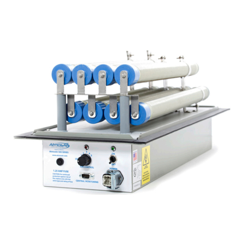
The AtmosAir 500 series, models 500F and 508F, bipolar ionization generators are industrial quality
units intended for installation in air conditioning systems or in custom designed air distribution
systems in commercial and industrial facilities. Custom designs include supply air distribution and
exhaust treatment systems. AtmosAir equipment is effective in reducing odors and harmful
pollutants through the introduction of positive and negative ions into the air stream to be treated.
The number and size of the ionization tubes used is dependent upon the airflow, size of the space,
and severity of the pollution and odors. The AtmosAir 500 series equipment is designed for minimal
maintenance efforts. The 500 series has two components that require inspection and maintenance:
1. AtmosAir 500 series bi-polar ionization generator
2. Ionization tubes
Because there are no moving parts the systems have low failure rates and minimal maintenance
requirements.
Product Diagram
AtmosAir 500 Series:
a. Circuit box
b. Fuse
c. 5-step power adjustment switch
d. Monitoring DB-9 output
connection
e. Power socket
f. Power switch
g. Green system power light
h. Red ionization power light
i. Ionization tubes
AtmosAir 500 series system equipment labeled.
Overall Dimensions:
Height and width: 209.6mm x 273.1mm; Length: 704.9mm
a
b
c
d
e
f
g
h
i

Installation
AtmosAir series equipment can be mounted in the side of a duct or air handler wall, using the
mounting flange and a weather strip gasket; or inside an air handler using a custom mounting rack.
In an air handler, the units operate best when located after the filters. Ideally, the tubes lie parallel
to the direction of airflow with the MCC tubes pointing upstream.
When installed in the side of a duct or air handler wall, the outer box and faceplate should not be
exposed to direct sunlight or moisture. If installing outside, a weatherproof enclosure with an access
panel for servicing should be installed over the AtmosAir box.
The AtmosAir 500 series operates on 110~250 VAC, 50/60 Hz; if using the optional remote
monitoring / control panel, the connection is made using a supplied 9-pin (DB-9) connector. The
tubes and electrode contacts should not come into contact with any conductive surface. A minimum
101.60mm clearance around the tubes is recommended. The box and all other exposed metal parts
are grounded.
Mechanical Installation
Carefully remove the equipment from its shipping container. Inspect the box, components, and
tubes for damage. Verify that the unit’s voltage rating is the same as the available voltage.
Orientation: Install the unit with tubes parallel to the airflow and the MCC end of the tubes on the
upstream side, whenever possible; otherwise, perpendicular orientation is acceptable. If multiple
units are installed in the same duct, stagger the units in the airflow so they are not in the same air
flow path. See illustrations on following page.
For induct installation: Verify the flange gasket is in place and in good shape to ensure the unit
seals properly. Make a cutout in the duct sized per the illustration and table on the following page.
Use the mounting bracket as a template for the mounting hole and mounting bolt locations. Cut
out the mounting hole and use a drill to create the mounting bolt holes. Twist all of the mounting
bolts into the mounting bracket. Place the mounting bracket into the pre-cut hole, then pull the
bracket towards you so that the pre-installed bolts go into each mounting bolt hole. Fold the 4 tabs
from the mounting bracket towards you so that they hold the mounting bracket (now inside of the
duct) to the outside of the duct. Place the AtmosAir unit onto the mounting bolts so that each bolt
goes through the corresponding hole in the AtmosAir unit and the AtmosAir tubes go fully inside of
the duct. Place the nuts on the bolts and tighten. It is not necessary to overtighten. The unit is
self-sealing to the duct so no further sealing is needed.
For in plenum/AHU installation: Mounting varies with rack-style. Follow mounting instructions
provided with rack. Typically, racks require 101.6 mm of clearance from walls.
Units should be installed to allow easy access for maintenance. Install units so that the power
switch and 5 step power adjustment knob is accessible.

Electrical Installation
Field install a junction box within 2.4m of the unit(s). Each 500 series unit is typically shipped with a
3m power lead in a flexible metallic conduit with a quick connect power plug on one end and bare
wires on the other.
The secondary voltage to the ionization tubes can be as high as 3000 volts AC. Do NOT connect to
power before the installation is complete and all personnel are aware of imminent operation. Always
disconnect power to the unit before handling any of the components.
DO NOT CONNECT THE IONIZATION UNIT DIRECTLY TO THE AHU POWER!! The surge and
sag when the AHU turns on can reduce the life of the AtmosAir system. We recommend operating
the unit on/off function with an air flow switch, air pressure switch or timer. We recommend using
whatever you are most comfortable with. Timers set for normal operating hours are the most reliable.
There is no harm if occasionally the ionization operates without air flow or the air flow operates
without ionization. Air flow or air pressure switches are most ideal; however we have found these
are often not sufficiently sensitive or are installed incorrectly and prevent the normal operation of the
ionization.
The unit is equipped with a normally closed relay that opens on ionization start-up and closes on
loss of power. This relay can initiate a local alarm or be tied into a building automation system.
Connection is via a D-subminiature 9-pin connector, DB-9. Pins 1 and 5, starting from the top left,
are the active pins.

!!!WARNING!!!
The secondary voltage to the ionization tube can be as high as 3000 volts AC. Do NOT connect
to power before the installation is complete and all personnel are aware of imminent operation.
Always disconnect power to the unit before handling any of the components.
!!!WARNING!!!
Operation
Once the system is properly installed and all personnel are clear of the high voltage tubes, the
system can be turned on:
Ensure the ionization power knob is turned all the way counter clockwise in the ‘off’ position.
Flip the power switch up to the ‘on’ position. The green embedded LED light above the power switch
should light up to indicate that the power is on and running to the system.
Set the ionization power knob to the appropriate setting (1-5, with 1 being low and 5 being high).
The red embedded LED above the power knob should light up to indicate that ionization has been
activated and high voltage is being sent to the tubes’ electrodes. The system is intended to deliver
ions into the treated area such that the ion levels should increase by 100 up to 1,500 positive and
negative ions / cm3. The desired ion increase is dependent on many factors, including space, use,
contaminant level and distribution effectiveness. An authorized AtmosAir design consultant should
recommend the desired ion increase and appropriate system layout. Optimization and tuning can be
provided by AtmosAir personnel.
!!!CAUTION!!!
A nonfunctioning LED light may improperly indicate that the system is not functioning. Besure to
disconnect fromthe mains power before performingmaintenance or troubleshootingthe system.
Maintenance Requirements
The maintenance requirements on an AtmosAir system are mainly site dependent; a dirtier
environment requires more frequent maintenance. In general, quarterly or biannual maintenance is
recommended along with tube replacement every two years. The local AtmosAir dealer can provide
you with a maintenance/service contract.
Other manuals for 500 Series
3
Table of contents
Other AtmosAir Air Cleaner manuals

AtmosAir
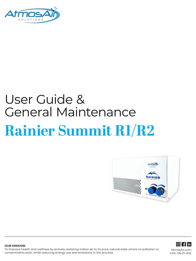
AtmosAir Rainier Summit R1 Instruction manual

AtmosAir
AtmosAir RIA SafeGuard Technical Document

AtmosAir
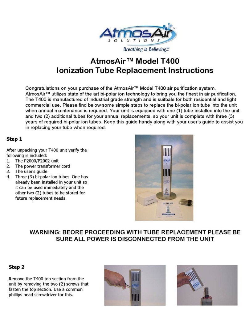
AtmosAir T400 Guide

AtmosAir
AtmosAir P2002 User manual

AtmosAir
AtmosAir Matterhorn 880 Technical Document

AtmosAir
AtmosAir FC-400 Series Technical Document

AtmosAir
AtmosAir 500 Series Technical Document

AtmosAir
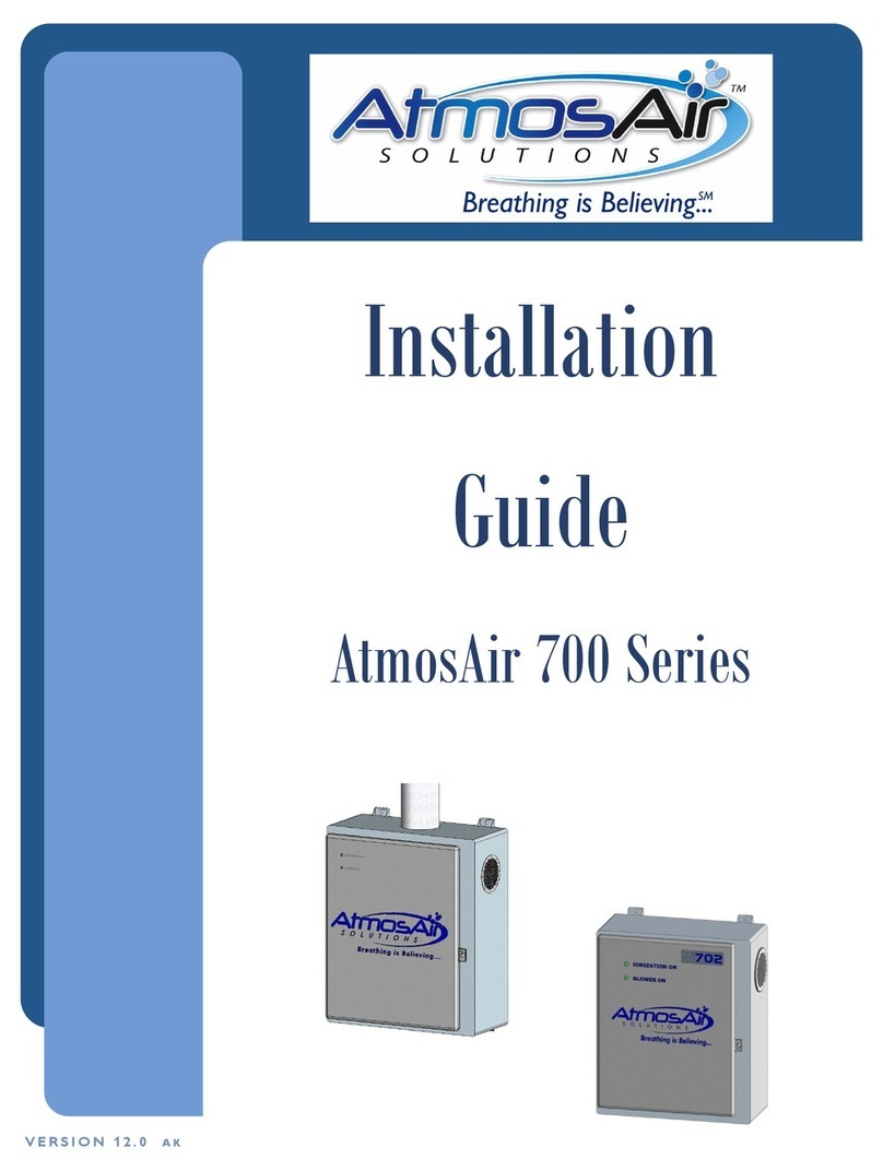
AtmosAir 700 series User manual

AtmosAir
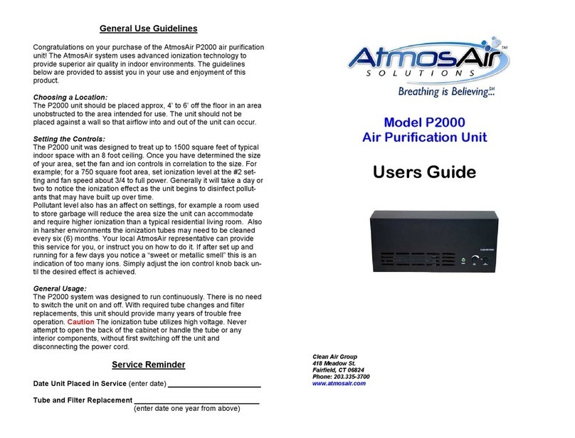
AtmosAir P2000 User manual

AtmosAir
AtmosAir AtmosSmart 500 Series Technical Document