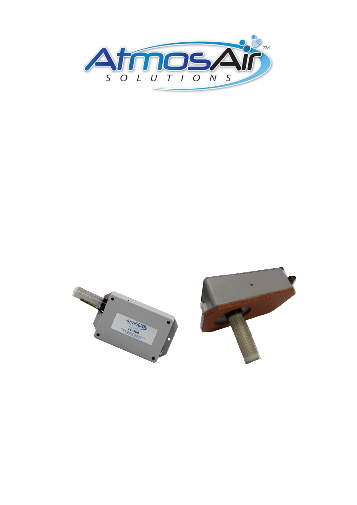
AtmosAir FC-400 Series Technical Document

Installation, Operations and
Maintenance Guide
AtmosAir
FC-400 & FC-400 FM

Visibly Cleaner Air
AtmosAir eliminates pollutants and restores air quality in commercial, industrial and residential buildings.
When you choose AtmosAir, you’ll refresh your indoor environment with the same clean, pure air found
only at the highest mountain elevations.
Product Overview
The AtmosAir FC-400 series, models FC-400 and FC-400 FM (Flush - Mount) ionization
generators are small residential-sized units intended for installation in air conditioning systems or
in custom-designed air distribution systems in small commercial spaces and typical residential
houses. AtmosAir equipment is effective in reducing odors and harmful pollutants through the
introduction of positive and negative ions into the air-stream to be treated. The number and size of
the ionization units used is dependent upon the airflow, size of the space, and severity of the
pollution and odors. The AtmosAir FC-400 series equipment is designed for minimal maintenance.
The FC- 400 series has two components that require inspection and maintenance:
1. AtmosAir FC-400 series base unit components + Fuse
2. Ionization tube
Because there are no moving parts, little maintenance is required and the systems have very low
failure rates and minimal maintenance requirements. For more information, read the AtmosAir FC-400
series submittal documents.
Product Diagram AtmosAir FC400 equipment, labeled
AtmosAir FC400 System
:
a. Female power plug receptacle
(Quick Disconnect)
b. Ionization tube
c. System power light
d. Mounting Holes
e. Fuse Holder
Overall Mounting Plate Dimensions:
FC-400/FC-400FM:
152.5mmL x 89mmW x 40.6mmH
FC400FM has a .200 silicone Foam
Gasket, for sealing.
c
e
d
76mm
c
e
a
152.5mm

Installation
AtmosAir FC-400 series equipment can be mounted in a duct (FC-400 FM) or, air handler wall or in
supply slot FC-400, using the faceplate mounting flange and its weather-strip gasket; or inside a plenum
using a universal mounting bracket. The units operate best when located after all filters, coils, and fans.
Various mounting arrangements are possible; however, the available options may be limited due to size
and configuration restrictions.
When mounted on the side of a duct or air handler wall, the enclosure should not be exposed to direct
sunlight or moisture. If installing outside, a weatherproof enclosure with an access panel for servicing
should be installed over the AtmosAir equipment.
The AtmosAir FC-400 series operates on 110~250 VAC, 50/60 Hz. The tube and electrode contacts
should not come into contact with any conductive surface. A minimum 63.5mm clearance around the
tube is recommended.
Mechanical Installation
Carefully remove the equipment from its shipping container. Inspect the main components, gasket, and
tube for damage. Verify that the unit’s voltage rating is the same as the available voltage, 110~250 VAC
50/60Hz.
Install the ionization tube: Gently pull the conductor strap back to allow the tube to turn freely; screw the
end screw of the tube into the tube- holder hand-tight. Ensure that the tube is fully seated. Do not over-
tighten the tube! Once the tube is secure, return the conductor strap to its normal position and ensure
solid and continuous contact is made with the tube’s outer mesh. The FC-400 series comes with a MCC
B tube installed.
Location and Orientation: Install the unit downstream of filters, coils, and fans with tubes perpendicular
to airflow whenever possible. If multiple units are installed in the same duct, stagger the units in the
airflow so they are not in the same airflow path.
For in-duct installation: Verify the flange gasket (FC-400FM) is in place and in good shape to ensure
the unit seals properly. Make a 63.5mm Diameter hole in the duct sized at for FC- 400FM use template
provided to locate and cut the cut-out hole, then cut out and with 63.5mm Hole Saw and mark the
locations of the mounting holes for the FC-400 and FC- 400FM. The universal bracket is intended for
duct installations where extra support of the unit is required. It may also be used for sheet-metal ducting.
The optional universal stainless steel bracket is meant to be installed on the inside of the duct, in a
position allowing tool access.

Mechanical Installation, continued
The bracket is designed to be bent for universal installation option. This bracket allows for various
mounting options. Mark the drill holes for the self-tapping screws to mount the FC- 400 to the Duct Wall
Affix the unit securely in the duct using self-tapping screws. Do not over-tighten, this may strip the screw-
hole. The unit is self-sealing to the duct so no further sealing is needed. (FC- 400 FM)
For in-plenum/AHU installation: Mounting varies with bracket-style. Follow mounting instructions.
Typically, provide 50.8mm tube of clearance from walls.
Units should be installed to allow easy access for maintenance. Install units so that the power adjustment
knob, fuse and status light are easily accessible, variable and visible.
Electrical Installation
AtmosAir FC400 series systems require approximately 7.68 watts. The FC-400 series can be wired
directly to blower circuits.
Follow proper electrical procedures, guidelines, and codes for providing power to the systems, including
requirements for conduit, sufficient ampacity, phase balancing, etc. Electrical installation should be
performed by a qualified electrician.
Field-install a power plug outlet or junction box within 1.82m of the unit(s).
Each FC-400 series unit is typically shipped with a 2.438m power cord with a field install pair of wire
hot/neutral connector on one end and a quick disconnect plug on the other end. FC-400FM has a
moisture-proof quick disconnect on the unit.
!!!WARNING!!!
The secondary voltage to the ionization tube can be as high as 2000 volts AC. Do NOT connect to power
before the installation is complete and all personnel are aware of imminent operation. Always disconnect
power to the unit before handling any of the components.
!!!WARNING!!!

Operation
Once the system is properly installed and all personnel are clear of the high voltage tubes, the system
can be turned on: DO NOT TOUCH TUBE
1. Ensure the ionization power knob is turned all the to the appropriate quadrant. From low to high
clockwise.
2. Plug the power cord into the plug receptacle on the FC-400 ionization system.
3. Turn the system on and set the ionization power knob to the appropriate setting Low, Med, High.
The green embedded LED light left of the power knob should light up to indicate that the system is on,
ionization has been activated, and high voltage is being sent to the tube.
4. Settings are determined upon commissioning and installation with the Criteria below:
The system is intended to deliver ions into the treated area such that the ion levels should increase by
350 up to 1500 negative ions / cm3. The desired ion increase is dependent on many factors, including
space, use, contaminant level, humidity RH and distribution effectiveness. An authorized AtmosAir
design consultant should recommend the desired ion increase and appropriate system layout.
!!!CAUTION!!!
A non-functioning LED light may improperly indicate that the system is not functioning. Be sure to
disconnect quick disconnect power before performing maintenance or troubleshooting the system.
!!!CAUTION!!!
Maintenance Requirements
The maintenance requirements on an AtmosAir system are mainly site- dependent. The FC-400 series
is designed for automatic operation and replacement of tube at 2 years 8,800 hours of long life. Once
commissioned, maintenance is minimal. A tube inspection is recommended at one year & in general,
bi-annual maintenance is recommended along with a tube replacement at a minimum of every two years.
The FC-400 series is provided with an internal fuse and a spare fuse is provided. The local AtmosAir
dealer can provide you with an annual service contract.
Quarterly / Bi-annual Maintenance Requirements:
•Visually check the performance of the system by checking the green light on the individual units. If
the light is on, and you can hear the ‘buzz’ of the tubes, then unit is functioning properly. If not, proceed
to the troubleshooting section for repair. Maintain a physical distance between all personnel and the
tubes while system is operating or turned on.

Maintenance Requirements, continued
Disconnect the system from the mains power before performing any maintenance steps.
•Inspect the unit’s enclosure, tube-holder, and the tube’s plastic end cap. Remove any particle build-
up. Thoroughly wipe clean any visible tracks or contaminates that have developed in the enclosure or
tubes.
•Inspect connections: tightness of the tube in the tube holder, the grounding clip, ensure that
grounding clip is clean and in contact with the mesh emitter and its screw. Do not open the enclosure,
or the warranty will be void.
•It may be beneficial to clean the tubes to improve performance. The tubes can be cleaned using an
air compressor for a quick clean, or more thoroughly with cleaning solutions. Do not immerse the tubes
in water. Ensure that the tube material and mesh are completely dry before re-installing.
2 Year Tube Replacements:
The ionization tubes should be replaced once every 24 months, at a minimum, as the production
efficiency slowly declines over time due to the stress caused by plasma and (lack of) cleanliness of the
electrodes. Old or excessively dirty tubes can also put undue stress on the transformer causing pre-
mature failure.
Troubleshooting
In the event that the system is not functioning, the first step is to check the power source and fuse:
•Check power plug for good connection and corrosion.
•Open Quick Disconnect plug and check for Power to Unit.
•Check that the main power supply is sending the correct power to the unit.
•If the system is controlled by an air pressure switch, or the fan blower switch, check that these are
not preventing power from being sent to the system.
If power is reaching the unit and it was necessary next step is to determine whether there is a fault in
the system or a tube. If all external sources of failure are eliminated, the system should be serviced by
a qualified AtmosAir technician.

Troubleshooting, continued
If the correct power is being supplied, the next step is to determine the cause of the failure.
Typically, failures are caused by arcing between the inner and outer electrodes, or between one
electrode and ground. This often occurs because of damaged tubes or dirty and/or wet conditions that
have allowed carbon tracking to temporarily connect to anode and cathode and/or a grounding point
electrically. (Short)
1. Ensure clean and complete contact of spring type electrode to Mesh Emitter.
2. Ensure barrel type male power plug is actually making complete contact with female receptacle in
the FC400.
3. Inspect the enclosure and tube cap for tracking evidence.
4. Inspect each tube for cracks, pitting, or other degeneration of the dielectric material that causes
the dielectric to fail and arcing to occur.
5. If physical inspection has not revealed the cause of failure, one may carefully observe the tubes as
the ionization system is turned on to determine whether arcing is occurring at a particular tube.
This may be visible as a spark.
6. It may be necessary to remove the tube to ensure that the transformer is working properly, use a
known good tube for functional check. In the absence of a tube. If the fuse still blows, then the
system should be serviced by a qualified AtmosAir technician.
Otherwise, replace the damaged tube, clean and smooth any mounting plate or end cap carbon tracking,
and return the system to service.
~~DO NOT open the enclosure, as this will void any warranties. ~~
If the cause of failure cannot be determined, please contact AtmosAir for further help.

Tube Cleaning Instructions
It may be beneficial to clean the tubes to improve performance, by removing dirt and grease from the
tube and mesh where it impairs the ability to generate the plasma for ion creation. The tubes can be
cleaned using an air compressor for a quick clean, or more thoroughly with cleaning solutions. Be sure
to disconnect the system from mains power before performing any cleaning.
Quick-Clean
Disconnect the system from the main power before performing any cleaning. Even if no person or object
is in contact with the system, the air flow may inadvertently cause dirt, debris, water, or other objects to
come into contact with an electrode or both electrodes and create a spark, if the system is operating.
Use a light-duty air compressor for a quick clean of the tubes. Sweep the airflow over the tubes to remove
the loose dirt and debris from the tubes. Clear the areas between and under the tubes with the air
compressor. It may be useful to remove the tubes for improved cleaning. Cleaning the general area
around the tubes to remove dust, dirt, and debris will keep the tubes clean longer.
CAUTION
Do not immerse the tubes in water. Ensure that the tube and mesh are completely dry before re-installing.
Thorough Clean
Disconnect the system from main power before performing any cleaning. Remove the tubes from the
system.
A more thorough method for cleaning the tubes is to separate the outer mesh from the tube and use mild
cleaning solutions.
1. Remove the mesh from the tube. Grasp the tube, not the end cap, while removing the mesh. Provide
firm but gentle pressure when holding the tube. It may be necessary to gently twist the mesh in sections
working from top to bottom until the entire length is loose enough to pull off.
2. Soak the mesh in a mild soap solution: 30ml of dish detergent per liter of water makes a great cleanser.
Or use running warm tap water in a sink, gently rub the mesh to remove dirt.
3. If you allow the mesh to soak for a few minutes, rinse the mesh thoroughly with water to remove all
traces of soap. Allow the mesh to dry completely.

Thorough Clean, continued
4. Clean the tube with a mild soap solution, and a soft cloth or sponge. A non-scratch scrub sponge may
help remove sticky material. Clean any carbon tracking residue off of the end cap. Rinse or wipe the
tube and dry thoroughly. Be sure to avoid the seal between the cap and tube and between the cap and
the end screw when rinsing.
5. Once the mesh and tube are completely dry, replace the mesh on the tube by sliding it gently over the
tube. Be sure that the outer mesh is at least 1.25 cm from the end cap, and that both vertical seams on
the inner and outer electrodes line up.
Once the tubes are clean and completely dry, reinstall the tubes in the system.
Tips on Tube Life
Cleaning the tube is beneficial because it reduces stress on the transformer and also removes any dirt
or oil that can inhibit the plasma from forming on the outside of the tube. Unfortunately, there are many
other factors that affect the efficiency and life of the tube:
The silicone seal between the tube and the cap keeps moisture from infiltrating the tube.
Excessive aluminum oxide build-up on the inner electrode can decrease the strength of the
plasma as the oxide essentially increases the thickness of the dielectric barrier.
The plasma discharges between the mesh and the tube slowly wears on the tube, thinning the
dielectric barrier. Eventually, repetitive stress from the discharges can create erosion holes.
Carbon tracking or cracks in the end cap should be gently cleaned by hand; these allow an
easy path for current to flow and creates a short in the system.
AtmosAir SolutionsTM mission is to bring and restore every indoor environment the same clean
and pure quality air that is typically found at higher mountain elevations.
AtmosAir’s unique and proven air purification process significantly reduces mold, controls the
spread of bacteria and airborne viruses, and reduces airborne particles that evade normal
filtration solutions. AtmosAir equipment uses non-thermal plasma technologies to generate bi-
polar ionization that attacks and breaks down odors and contaminants.
Other manuals for FC-400 Series
1
This manual suits for next models
1
Table of contents
Other AtmosAir Air Cleaner manuals

AtmosAir
AtmosAir 500 Series Technical Document

AtmosAir
AtmosAir P2000 User manual

AtmosAir
AtmosAir 500 Series Technical Document

AtmosAir
AtmosAir 700 series User manual

AtmosAir
AtmosAir Matterhorn 880 Technical Document

AtmosAir
AtmosAir P2002 User manual

AtmosAir
AtmosAir T400 Guide

AtmosAir
AtmosAir RIA SafeGuard Technical Document

AtmosAir
AtmosAir FC-100 Series Technical Document

AtmosAir
AtmosAir AtmosSmart 500 Series Technical Document