AtmosAir Matterhorn 880 Technical Document

OUR MISSION
To improve health and wellness by actively restoring indoor air
to its pure, natural state where no pollution or contaminants
exist, while reducing energy use and emissions in the process.
AtmosAir.com
CAG-06-21-003
IMPORTANT
Save this Document
for Future Reference &
Warranty Information
Maerhorn 880/882
Installation, Operation
and Maintenance Guide

Installation, Operation & Maintenance Guide Matterhorn 880/882 2
1-888-MY-AIR11 CAG-06-21-003 AtmosAir.com
! I M P O RTA NT !
READ THIS BEFORE STARTING INSTALLATION.
DO NOT THROW AWAY THIS GUIDE.
How to Contact Us: If you need help, please contact an
AtmosAir Representative for technical assistance.
For safe installation you MUST:
■Always disconnect power to the unit before handling any of the
components.
■DO NOT connect to the power before the installation is complete and
personnel are aware of the imminent operation. Secondary voltage to the
ionization tube can be as high as 3000 Volts AC.
■Carefully read this instruction booklet before beginning the installation.
■Follow each installation or repair step exactly as shown and explained in
this guide.
■Observe all local, state, national and international electrical codes.
■Pay close attention to all warnings and caution notices given in this guide.
!CAUTION!
Do not touch while in operation shut off electricity before servicing!
This equipment should be inspected frequently and collected dirt removed from it regularly to prevent excessive
accumulation that may result in ashover or risk of re.
!MISE EN GARDE!
Ne touchez pas pendant le fonctionnement couper l’électricité avant l’entretien
Cet équipement doit être inspecté fréquemment et la saleté collectée doit être retirée régulièrement pour éviter
toute accumulation excessive pouvant entraîner un contournement ou un risque d’incendie.

Installation, Operation & Maintenance Guide Matterhorn 880/882 3
1-888-MY-AIR11 CAG-06-21-003 AtmosAir.com
Table of Contents
01 PRODUCT OVERVIEW 4
Control Panel Diagram 4
02 INSTALLATION 5
Mechanical Installation 5
Mechanical Installation Continued 6
Duct Cut-Out and Quick Change Plate Procedure 7
Duct Cut-Out and Quick Change Plate Procedure Continued 8
Electrical Installation 8
Installation Dimensions 9
03 FIELD WIRING DIAGRAM 10
04 OPERATION 11
05 MAINTENANCE REQUIREMENTS 11
06 TROUBLESHOOTING 12
07 MECHANICAL INSTALLATION ILLUSTRATIONS 13
08 EXPLANATION OF TECHNOLOGY 14
09 PRODUCT WARRANTY 15

Installation, Operation & Maintenance Guide Matterhorn 880/882 4
1-888-MY-AIR11 CAG-06-21-003 AtmosAir.com
01 PRODUCT OVERVIEW
The AtmosAir Matterhorn 880 series, models Matterhorn
880 and 882 ionization generators are commercial and
residential-sized units intended for installation in air
conditioning systems or in custom-designed air distribution
systems in small commercial spaces and typical residential
houses. AtmosAir equipment is effective in reducing odors
and harmful pollutants through the introduction of positive
and negative ions into the air stream to be treated. The
number and size of the ionization tubes used, is dependent
on the airow, size of the space, and severity of the pollution
and odors. The Matterhorn 880/882 is a 220-250 VAC unit
equipped with one (1) tube. However, it is capable of being
supplied with two (2) tubes. The Matterhorn 882 is always
equipped with two (2) specied tubes. The AtmosAir
Matterhorn 880 series equipment is designed for minimal
maintenance efforts. The 880 series has two components that
require inspection and maintenance:
1. AtmosAir Matterhorn 880 series base unit components
2. Ionization tubes
Because there are no moving parts, little maintenance is
required, and the systems have very low failure rates. For
more information, read the AtmosAir Matterhorn 880 series
submittal documents.
Control Panel Diagram
AtmosAir 880/882 Series Control Panel Layout:
Tube
Size
Tube
Number
Flowrate
(CFM)
mm / inch
of WG
Pascals
(Pa)
Steady
State (mA)
M-880
C 1 1000 0.0102mm
0.0004” 0.01 34
D 1 1500 0.10156mm
0.0040” 1.00 35
E 1 2000 0.10156mm
0.0040” 1.00 35
F 1 2500 0.3048mm
0.0120” 2.99 37
M-882
C 2 2000 0.2032mm
0.0080” 2.00 34
D 2 3000 0.6121mm
0.0241” 6.00 35
E 2 4000 1.2243mm
0.0482” 12.00 35
F 2 5000 1.7348mm
0.0683” 17.00 37
Pressure Drop calculated at airow velocity of 1500 f/m (7.62 m/s)
Pressure Drop Chart
A. Power Transformer - Inside
B. Fuse Drawer (+1 Spare Fuse)
C. Power Cord Socket
D. 5-Step Ion Level Adjustment Knob
E. System Power Light
A
D
C
B
E
Overall Mounting Plate Dimensions:
Height and Width: 222.25mm (8 ¾“) x 215.90mm (8 ½”)

Installation, Operation & Maintenance Guide Matterhorn 880/882 5
1-888-MY-AIR11 CAG-06-21-003 AtmosAir.com
02 INSTALLATION
AtmosAir 880 series equipment can be mounted in an air handler
wall, using the faceplate mounting ange and its weather-strip
gasket; or inside a plenum using a semi-custom mounting
bracket. The units operate best when located after all lters,
coils, and fans. Various mounting arrangements are possible;
however, the available options may be limited due to size and
conguration restrictions. Use the Duct Cut-Out Procedure for
ideal placement of the Matterhorn 880/882 models.
When mounted on the side of a duct or air handler wall, the
enclosure should not be exposed to moisture. If installing
outside, a weatherproof enclosure with an access panel for
servicing should be installed over the AtmosAir equipment.
Contact AtmosAir Sales for A.W.E. specications.
The AtmosAir Matterhorn 880 series operates on 220-250
VAC, 50/60 Hz. The tube and electrode contacts should not
come into contact with any conductive surface. A minimum
101.6mm (4”) clearance around the tube is recommended.
Mechanical Installation
1. Carefully remove the equipment from its shipping
container. Inspect the main components, gasket, and
tube(s) for damage. Verify that the unit’s voltage rating is
the same as the available voltage, 220-250 VAC.
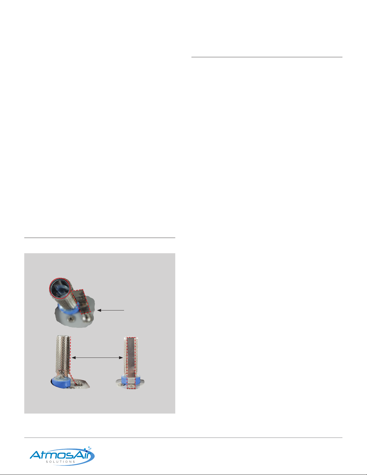
2. Install the ionization tube: Gently pull the conductor
strap back to allow the tube to turn freely; screw the end
screw of the tube into the tube holder hand-tight utilizing
the blue cap, DO NOT TWIST THE TUBE OR MOVE THE
EMITTER SCREEN. DO NOT OVER-TIGHTEN THE TUBE!
Once the tube is secure, return the conductor strap to its
normal position and ENSURE SOLID, FLAT CONTACT IS
MADE WITH THE TUBE’S OUTER MESH.
3. Location and Orientation: Install the unit downstream
of lters, coils, and fans with the ionization tubes vertical
whenever possible (When installing a dual F Tube setup,
the tubes MUST be mounted vertically, and ‘S’ clips are
recommended); If multiple units are installed in the same
duct, stagger the units in the airow so they are not in the
same airow path.
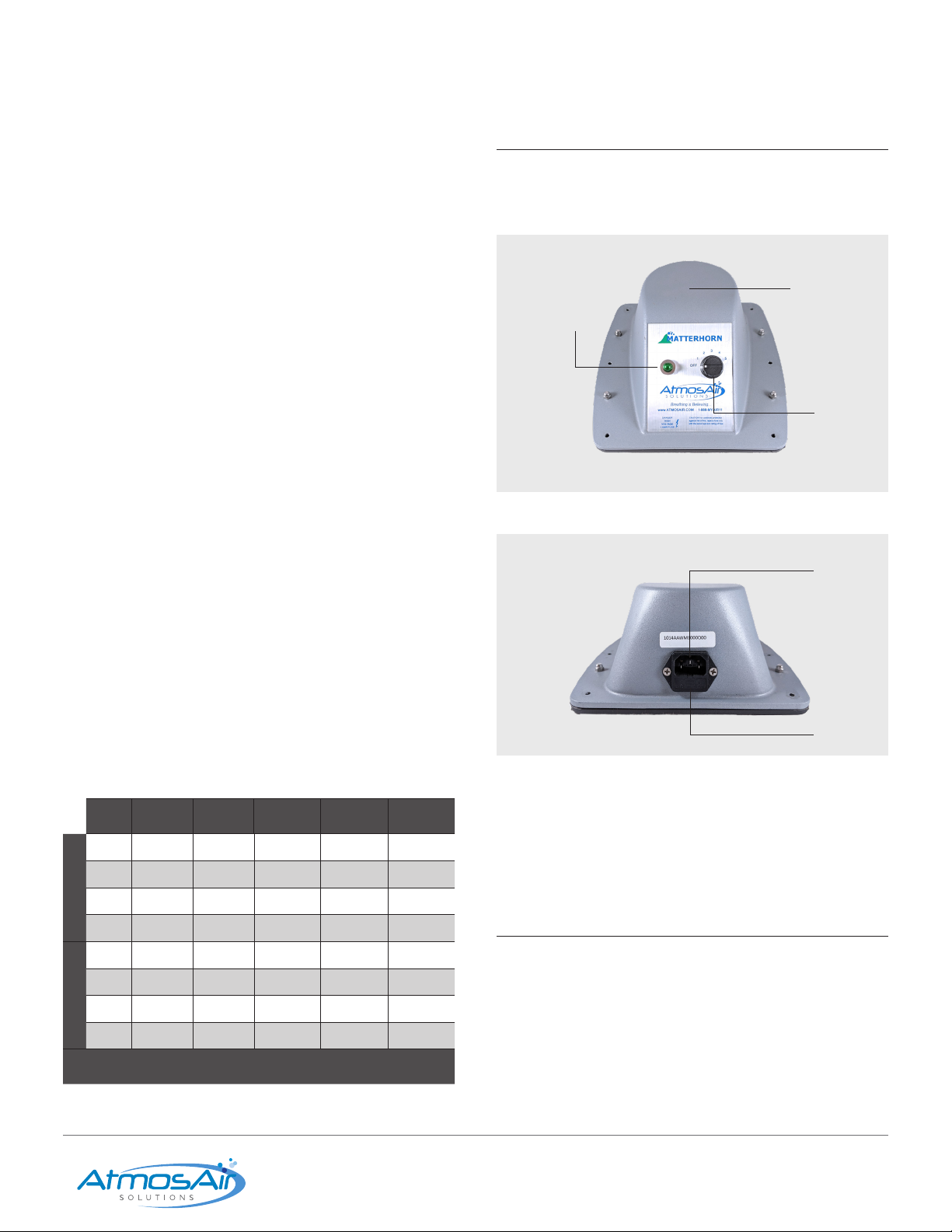
4. The standard Matterhorn 880/882 power cord is 3.05
meter (10’) long. Be sure to consider receptacle location in
your placement plan. The receptacle or junction box must
be within 2.45 meters (8’) of the M880/882.
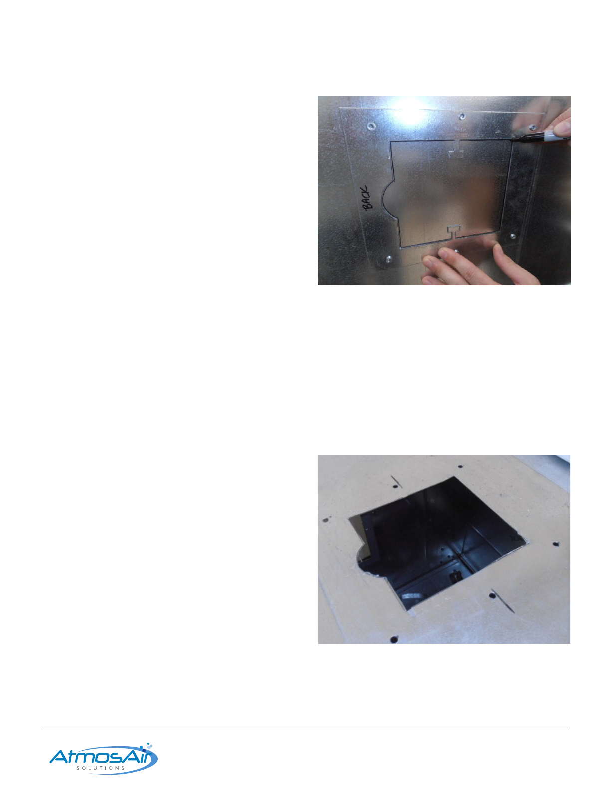
5. For in-duct installation: Verify the ange gasket is in
place and not damaged to ensure the unit seals properly.
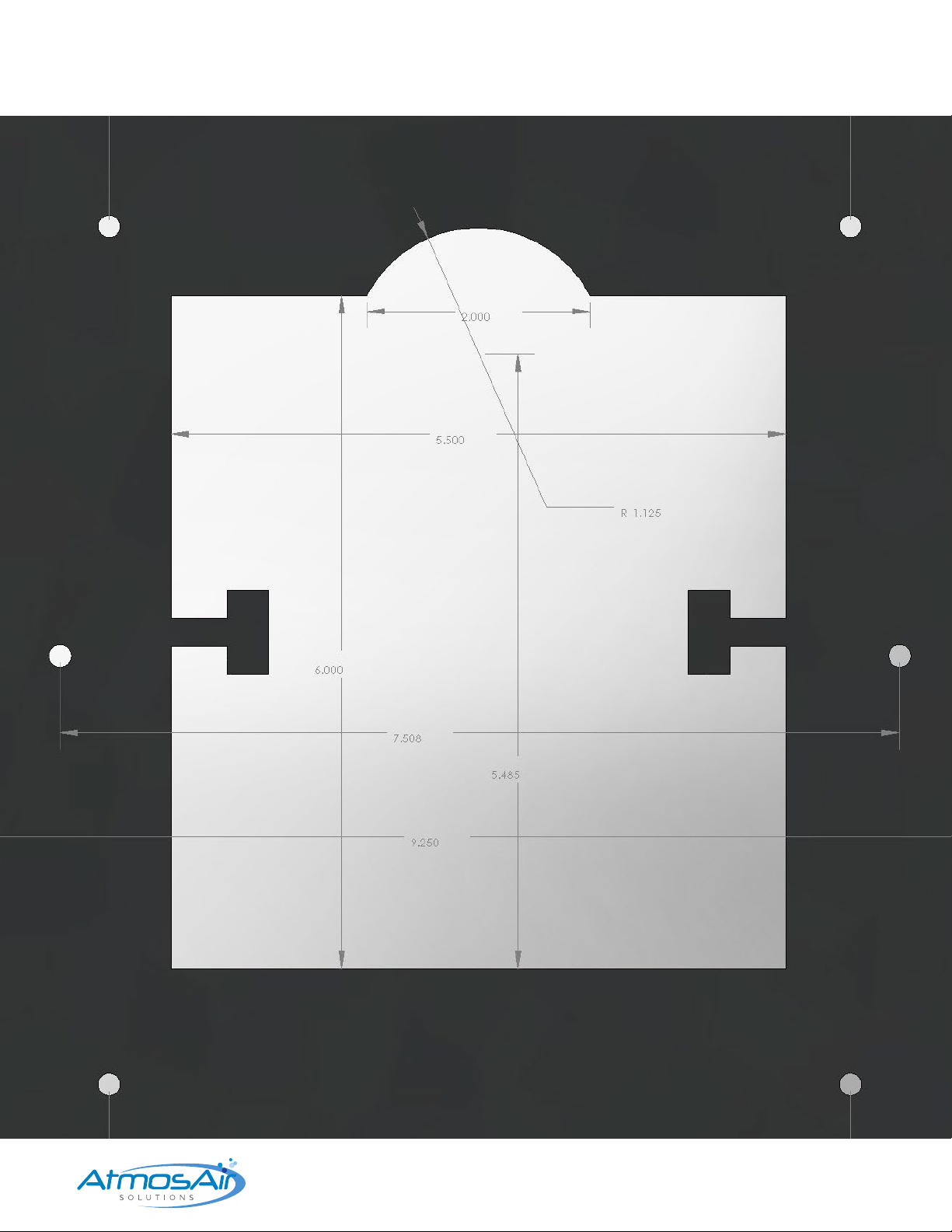
When making a cut-out in the duct, ensure there is at least
25.4 mm (1”) clearance from the duct wall on all four sides
before cutting the 139.7mm (5½”) high × 152.4 (6”) wide
mounting cut-out. A galvanized steel template is included
for ease of installation; use the inner lines to cut the cut-
out hole, then trace the cut-out and mark the locations
of the mounting holes for the Matterhorn 880 series. The
semi-circular cutout in the template should be oriented
upstream if possible.
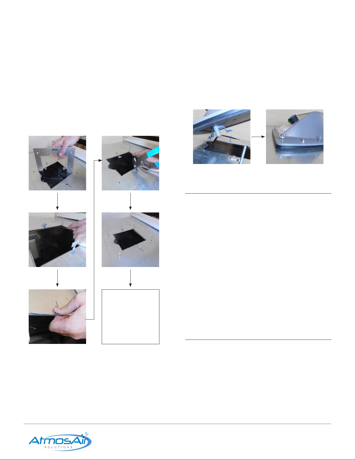
6. Using the marked holes from the backer-plate template,
afx the unit securely in the duct using self-tapping
screws (if not using backer-plate). Do not over-tighten,
this may strip the screw hole. The unit is self-sealing to the
duct, so no further sealing is needed.
Continue on Next page
Not Acceptable
Acceptable

139.7mm
5.5“
152.4mm
6”
Installation, Operation & Maintenance Guide Matterhorn 880/882 6
1-888-MY-AIR11 CAG-06-21-003 AtmosAir.com
7. For in-plenum/AHU installation: Mounting varies with
bracket-style. Follow mounting instructions provided
with custom bracket. Typically, provide 101.6mm (4”) of
clearance from walls. Contact AtmosAir Sales for bracket.
8. Units should be installed to allow easy access for
maintenance. Install units so that the 5-step power
adjustment knob and status light are easily accessible and
visible.
9. In the case of the M880, the second (forward-most) spring
tang should be bent 90° upward, away from the rear tube
and blue bracket.
Overall Product Dimensions
Matterhorn 882 Shown
Duct Cut-Out Dimensions
222.3mm
8.75”
101.6mm
4”
25.4mm
1”
215.9mm
8.5”
C Tube – 187.45mm (7.38”)
D Tube – 254.0mm (10.0”)
E Tube – 365.25mm (14.38”)
F Tube – 568.45mm (22.38”)

Installation, Operation & Maintenance Guide Matterhorn 880/882 7
1-888-MY-AIR11 CAG-06-21-003 AtmosAir.com
Duct Cut-Out and Quick Change
Plate Procedure
PLEASE READ ENTIRE PROCEDURE BEFORE STARTING:
Notes:
■Utilize the Quick-Change Plate (Q.C.P.) in thin ducts,
berboard ducts or where relatively frequent dismounts
may occur.
■Additionally, the Q.C.P. may be used to compress loose
berglass insulation and prevent damage due to airow.
■It is not necessary to use the Q.C.P. in all instances. #10
self-tapping screws are provided for other instances. Screw
directly into duct. Use the Q.C.P. as the template for cut-out
of duct.
■Provide enough electronic clearances for the tubes, no
metal tube parts, or brackets may contact any part of the
duct, 38.1mm (1.5”) of clearance is recommended.
Procedure:
1. Always measure for clearances for the tubes and wires prior to
any other steps. Then, place the Q.C.P. in the appropriate area.
2. Holding the Q.C.P. in place, use a marker to trace the INNER
perimeter as shown in the image in the bottom-left. *Skip the “T”
clamp features when tracing*.
3. Before removing the Q.C.P., also use the marker to mark the
center point of the 6 PEM-NUT holes.
4. Using appropriate tools, cut out the traced area in the duct.
INSIDE PERIMETER.
5. Drill out the 6 marked holes with a 5 mm (3/16”) or 6.5 mm (¼”)
drill bit. NOTE: The Q.C.P. is sized so it will JUST slip into duct at an
angle as shown in the image in the bottom-right.
6. DO NOT Screw in the 8-32 × 38.1mm (1.5”) long screws
(provided) in from the BACK of the Q.C.P. until AFTER you
have placed the Q.C.P into the duct through the cut-out.
7. Align the Q.C.P so that the PEM-NUTS are protruding into
the duct, at-side towards the duct wall. (This is so the
Q.C.P will sit ush to the inside of a duct.)
Continue on Next page

Installation, Operation & Maintenance Guide Matterhorn 880/882 8
1-888-MY-AIR11 CAG-06-21-003 AtmosAir.com
8. Using the ‘T’ Clamp features in the Q.C.P, atten the T
clamps rst with your thumb and then ush with the Plier.
This feature is so the Q.C.P will not fall back through the
hole. Then tighten screws securely.
9. Insert Tube(s) into the Matterhorn. Ensure that the Blue
angled bracket is UNDER the Q.C.P.
10. Angle the Matterhorn into position with the BLUE tube
bracket toward the semi-circular cut out.
11. Align Screws through the holes in Matterhorn and place
Matterhorn into position.
12. Install wing nuts and snug down until gasket is
half compressed.
Electrical Installation
AtmosAir Matterhorn 880/882 series systems require
approximately 6 watts per tube. An internal 1-amp, slow-blow
fuse protects the unit.
■Follow proper electrical procedures, guidelines, and codes for
providing power to the systems, including requirements for
conduit, sufcient ampacity, phase balancing, etc. Electrical
installation should be performed by a qualied electrician.
■Field-install a power plug outlet or junction box within 8 feet
(2.5 m) of the unit(s).
■Each Matterhorn 880/882 series unit is typically shipped with
a 10-foot power cord with a C-30 connector on one end and
a 3-prong NEMA 5-15 plug on the other end. The plug can be
cut off and wires stripped for junction box installations.
Go to next step
NOTE: TUBE INSTALLATION NOT SHOWN IN THESE PICTURES.
Caution!
A non-functioning LED light may improperly indicate that the system
is not functioning. Be sure to disconnect from the main power before
performing maintenance or troubleshooting the system.
Dimensions on Next Page

Installation, Operation & Maintenance Guide Matterhorn 880/882 9
1-888-MY-AIR11 CAG-06-21-003 AtmosAir.com
Contact Us
1-888-MY-AIR11
(1-888-692-4711)
Matterhorn 880/882 Installation, Operation, and Maintenance Guide Page 9
www.AtmosAir.com CAG-02-21-002

Installation, Operation & Maintenance Guide Matterhorn 880/882 10
1-888-MY-AIR11 CAG-06-21-003 AtmosAir.com
PROVEN
GOOD GROUND
BLACK/BROWN
HOT 120V/240VAC
50/60 Hz SUPPLY
REMOTE
CONTROL AND
MONITOR
FROM
BMS(BACNET)
DUCT WALL
MOUNT
M-880/
882
AMBIENT
SAMPLING
PORT
BLACK/BROWN
HOT 120V/240VAC
50/60 Hz SUPPLY
WHITE/ BLUE= NEUTRAL
GREEN=GROUND
TO BACNET SYTEM
24V. MONITOR ON/ FAULT
TO BACNET SYTEM
24V. MONITOR ON/ FAULT
TO BACNET SYTEM
24V. CONTROL- ON/ OFF
24" (61 CM)
RJ-45 UMBILICAL
FIXED
ALL SPECIFICATIONS HEREIN;
PROPRIETARY TO ATMOSAIR
SOLUTIONS, SUBJECT TO CHANGE
AIRFLOW
SWITCH
AIRFLOW SWITCH
AHU/DUCT PRESSURE
SAMPLING TUBE
METAL
JUNCTION
BOX
WHITE/ BLUE= NEUTRAL
BLACK/BROWN
HOT 120V/240VAC
SUPPLY
PROVEN
GOOD GROUND
BLACK/BROWN
HOT 120V/240VAC
SUPPLY
M882 FIELD
DO NOT SCALE DRAWING
M-880 , M882 FIELD
WIRING DIAGRAM
SHEET 1 OF 1
UNLESS OTHERWISE SPECIFIED:
SCALE: 1:5
WEIGHT:
REV.
A
DWG. NO.
A
SIZE
TITLE:
NAME
DATE
COMMENTS: 240 VAC (NOM.) 50/60 HZ
Q.A.
MFG APPR.
ENG APPR. TA 9/15/2017
CHECKED E.E. DD 9/15/2017
DRAWN HRG 9/14/2017
FINISH
MATERIAL
INTERPRET GEOMETRIC
TOLERANCING PER:
DIMENSIONS ARE IN INCHES
TOLERANCES:
FRACTIONAL
.010
ANGULAR: MACH
BEND
TWO PLACE DECIMAL
.010
THREE PLACE DECIMAL
APPLICATION
USED ON
NEXT ASSY
PROPRIETARY AND CONFIDENTIAL
THE INFORMATION CONTAINED IN THIS
DRAWING IS THE SOLE PROPERTY OF
ATMOSAIR SOLUTIONS. ANY
REPRODUCTION IN PART OR AS A WHOLE
WITHOUT THE WRITTEN PERMISSION OF
ATMOSAIR SOLUTIONS IS PROHIBITED.
5
4
3
2
1
ATMOSAIR SOLUTIONS
M-880
M-882
03 FIELD WIRING DIAGRAM

Installation, Operation & Maintenance Guide Matterhorn 880/882 11
1-888-MY-AIR11 CAG-06-21-003 AtmosAir.com
04 OPERATION
Once the system is properly installed and all personnel are
clear of the high voltage tubes, the system can be turned on:
1. Ensure the ionization power knob is turned all the way
counterclockwise in the ‘off’ position.
2. Plug the power cord into the plug receptacle on the
ionization system.
3. Turn the system on and set the ionization power knob to
the appropriate setting (1-5, with 1 being low and 5 being
high). The green embedded LED light left of the power
knob should light up to indicate that the system is on,
ionization has been activated, and high voltage is being
sent to the tubes.
The system is intended to deliver ions into the treated area
such that the ion levels should be between 500 and 1500
negative ions / cm3. The desired ion increase is dependent
on many factors, including space, use, contaminant level,
humidity RH, and distribution effectiveness. An authorized
AtmosAir design consultant should recommend the desired
ion increase and appropriate system layout.
05 MAINTENANCE
REQUIREMENTS
Caution!
A non-functioning LED light may improperly indicate that the system
is not functioning. Be sure to disconnect from the main power before
performing maintenance or troubleshooting the system.
The maintenance requirements on an AtmosAir system are
mainly site-dependent; a heavily contaminated environment
may require more frequent inspection and maintenance.
Annual system maintenance is recommended. In general,
quarterly or semi-annual maintenance is recommended
along with a bi annual tube replacement is required. Your
local AtmosAir dealer can provide you with an annual
service contract.
Recommended Maintenance Procedures:
■Visually check the performance of the system by checking
the red and green lights on the individual units. If both lights
are on, then the unit should be functioning properly. If not,
proceed to the troubleshooting section for repair. Maintain a
physical distance between all personnel and the tubes while
system is operating or turned on.
■Optional: Check performance using a high voltage probe
(minimum of 5000 V; contact AtmosAir for additional
minimum probe specications) paired with a multimeter.
Follow proper safety procedures for dealing with high
voltages. If you are uncertain, do NOT perform any
maintenance with the power on and, instead, proceed to the
next step.
■Disconnect the system from the mains power before
performing any maintenance steps.
■Inspect the unit box, plastic tube caps, and tube-mounting
plate. Remove particles from mounting plate, and thoroughly
wipe clean any tracks or grooves that may have developed in
the plate or caps.
■Inspect connections: tightness of all nuts and screws; remove
deposits on the connections using sandpaper or wire brush -
it may be necessary to remove the tubes for this step.
■It may be benecial to clean the tubes to improve
performance. The tubes can be cleaned using an air
compressor for a quick clean, or more thoroughly with
cleaning solutions. Do not immerse the tubes in water.
Ensure that the tubes and mesh are completely dry before
re-installing. Install emitter mesh equidistant on the
composite tube area.
Tube Replacements:
Bi-annual tube inspections are recommended, in addition to
tube replacements once every two years as the production
efciency slowly declines over time due to the stress caused
by plasma and (lack of) cleanliness of the electrodes. Old
or excessively dirty tubes can also put undue stress on the
transformer causing premature failure.

Installation, Operation & Maintenance Guide Matterhorn 880/882 12
1-888-MY-AIR11 CAG-06-21-003 AtmosAir.com
06 TROUBLESHOOTING
In the event that the system is not functioning, follow these
steps IN ORDER:
1. Check the fuse. If it is blown, replace it with the
appropriately sized slow-blow 1 A glass 5 mm × 20 mm fuse
rated at 250 V and continue to the next step.
2. Check that the main power supply is sending the correct
power to the unit.
3. If the system is controlled by an air pressure switch, and/or
a door switch, check that these are not preventing power
from being sent to the system.
4. If power is reaching the unit and it was necessary to
replace the fuse, the next step is to determine whether
there is a fault in the system or a tube. First, to check that
the system’s power is functioning, set the ionization power
knob and the power switch both to the ‘off’ position. Make
sure all personnel are clear of the high voltage tubes, then
re-connect the power supply. Rotate the Ion level dial to #1
and observe the green light. If the light does not turn on,
there is a power delivery problem. If all external sources
of failure are eliminated, the system should be serviced
by a qualied AtmosAir technician. Please see contact
information at the bottom of this page.
The next step is to determine the cause of the failure, or blown
fuse. Typically, failures are caused by arcing between the
inner and outer electrodes, or between one electrode and
ground. This often occurs because of damaged tubes or dirty
and/or wet conditions that have allowed carbon tracking to
temporarily connect two electrodes and/or a grounding point
electrically.
5. Inspect the enclosure and tube cap for tracking evidence.
6. Inspect the tubes for cracks, pitting, or other
degeneration of the dielectric material that causes the
dielectric to fail and arcing to occur. Inspect the tube for
black dots indicating failed dielectric.
7. If physical inspection has not revealed the cause of failure,
one may carefully observe the tubes as the ionization
system is turned on to determine whether arcing is
occurring at a particular tube. The fuse will usually blow,
again, but for a short time, one may observe the cause
of the power surge in the form of a visual or audio cue.
Usually, a failing tube can be determined in a darkened
room by looking for a ash or arc from the failing tube.
The M880/M882 must be dismounted and carefully
turned upside-down. Do not allow the unit to roll onto
the ion level knob as this may damage it. If the tubes are
functioning properly, they will buzz.
8. It may be necessary to remove all the tubes to ensure
that the transformer is working properly in the absence
of tubes. If the fuse still blows, then the system should be
serviced by a qualied AtmosAir technician.
9. It is recommended to also check the voltage levels of
the system when a fuse has blown and been replaced,
to ensure that the transformer has not been irreparably
damaged (See step 4 for more information on this
process.) If the voltages are lower than expected, check
that all the connections are secure and rust-free; also
check that the input voltage is approximately 220-250
VAC. The technician must use a high voltage probe!
10. If the fuse blows, then the system should be serviced by
a qualied AtmosAir Technician. You can contact repair
services at RMA@atmosair.com or by contacting us at
1-888-MY-AIR11.
11. If the fuse continuously blows, or if the voltages are lower
than expected, then the system should be serviced by a
qualied AtmosAir technician.
12. Otherwise, replace the damaged tube(s), clean and
smooth any mounting plate or end cap carbon tracking,
and return the system to service.

Installation, Operation & Maintenance Guide Matterhorn 880/882 13
1-888-MY-AIR11 CAG-06-21-003 AtmosAir.com
07 MECHANICAL INSTALLATION ILLUSTRATIONS
Above: Matterhorn 882 Ionization
unit. Here you will see there are
two Ionization Tubes installed
illustrating how the ‘Spring Tangs’
are at against the tube.
With the power plug removed, use
a athead screwdriver to pop the
fuse drawer towards you.
Above: Matterhorn 880 Ionization unit. Here you will see there is one Ionization
Tube installed towards the center of the device. (This should always be installed
with the tube closest to the center of the unit.) The remaining unused ‘Spring
Tang’ should be CAREFULLY bent by hand to a 90° angle. Please see the closer
illustration above.
Once popped loose, pull the drawer
completely out towards you.
The ‘operating’ fuse is now exposed,
along with the spare fuse (right).
Spare Fuse

Installation, Operation & Maintenance Guide Matterhorn 880/882 14
1-888-MY-AIR11 CAG-06-21-003 AtmosAir.com
08 EXPLANATION OF TECHNOLOGY
AtmosAir Solutions’ ™ mission is to bring and restore every indoor environment the same clean and pure quality air that is typically
found at higher mountain elevations.
AtmosAir’s unique and proven air purication process signicantly reduces mold, controls the spread of bacteria and airborne
viruses, and reduces airborne particles that evade normal ltration solutions.
AtmosAir equipment uses non-thermal plasma technologies to generate bi-polar Ionization that attacks and breaks down odors
and contaminants.

Installation, Operation & Maintenance Guide Matterhorn 880/882 15
1-888-MY-AIR11 CAG-06-21-003 AtmosAir.com
y
y
CLEAN AIR GROUP, INC. – PRODUCT WARRANTY
Clean Air Group, Inc. d/b/a AtmosAir Solutions (“Clean Air Group”) warrants to the original purchaser of this product (“Customer”),
that should it prove to be defective by reason of improper materials or workmanship, for twenty-four (24) months from the date
of installation, or twenty-seven (27) months from the date of Clean Air Group’s delivery of the product, whichever occurs first,
Clean Air Group shall repair or replace the product without charge to the Customer. Proof of malfunction and return of the non-
working product must be presented by the Customer if submitting a warranty claim. This warranty is invalid if the factory applied
serial number has been altered or removed from the product. This warranty does not cover damage due to acts of God, misuse,
abuse, negligence, or modification of or to any part of the product. This warranty does not cover damage due to improper
installation, operation or maintenance, connection to improper voltage or electrical supply, or repair by anyone other than an
authorized Clean Air Group service provider. To obtain warranty service the Customer must: (1) provide proof of purchase in
the form of a Bill of Sale or receipted invoice, with evidence that the product is within the warranty period; (2) request a Return
Merchandise Authorization (“RMA”) from Clean Air Group prior to shipping; and (3) ship the product with the RMA to Clean Air
Group, freight prepaid, in either its original packaging or packaging affording an equal degree of protection. The product should
be delivered to AtmosAir, 2115 East Cedar Street, Suite 6, Tempe, AZ 85281. All transportation charges and shipping expenses
are the Customer’s responsibility. Clean Air Group will return the product by the same method it receives the product. A product
returned for repair after the warranty period, or that shows damage outside of the warranty coverage described herein, shall be
repaired for a reasonable charge as determined by Clean Air Group. The Customer will be advised of the cost of repair or
replacement before Clean Air Group proceeds.
THE OBLIGATIONS OF CLEAN AIR GROUP HERIN ARE EXPRESSLY GRANTED IN LIEU OF ALL WARRANTS, WHETHER
EXPRESS OR IMPLIED, INCLUDING BUT NOT LIMITED TO IMPLIED WARRANTIES OF MERCHANTABILITY AND FITNESS
FOR A PARTICULAR PURPOSE. ALL IMPLIED WARRANTIES INCLUDING WARRANTIES OF MERCHANTABILITY AND
FITNESS FOR PARTICULAR PURPOSE ARE LIMITED TO THE TERM OF THE EXPRESS WARRANTY GRANTED HEREIN.
Some states do not allow limitations on how long an implied warranty lasts, so the foregoing limitation or exclusion may not apply
to you.
With the exception of damages resulting from Clean Air Group’s failure to comply with any obligation under federal or state
warranty laws, Clean Air Group SHALL NOT BE LIABLE TO THE CUSTOMER OR ANY OTHER PERSON OR THIRD PARTY
FOR ANY DAMAGES, INCLUDING BUT NOT LIMITED TO CONSEQUENTIAL, SPECIAL, INDIRECT, INCIDENTAL AND
PUNITIVE DAMAGES AND/OR DAMAGES BY REASON OF INJURY TO ANY PERSON DUE TO ANY DEFECT OR
MALFUNCTION OF THE PRODUCT OR ANY PART OR PARTS THEREOF OR FOR ANY OTHER REASON. This warranty
gives you specific legal rights and you may have rights which vary from state to state. If your product is defective please contact
Clean Air Group or the dealer where you purchased the unit.
Disclaimer: The air purification technology provided by AtmosAir is intended to improve air quality. It is not intended to replace
reasonable precautions to prevent the transmission of airborne contaminants. Customer, its employees, invitees and all persons
having access to the serviced premises should comply with all applicable public health laws and guidelines issued by federal,
state and local governments and health authorities such as the Centers for Disease Control and Prevention (CDC). These
precautions include but are not limited to wearing face masks, social distancing, hand hygiene and appropriate sanitizing and
disinfecting. Clean Air Group does not assert that its products can protect people from viruses, bacteria or other airborne
contaminants, expressly excludes liability for loss or damage arising from any such claims, and does not assume any liability for
the consequences arising out of the application, use or misuse of its products, including any injury or damage to any person or
damage to any property as a matter of product liability, negligence, contract or otherwise.
Manufacturer,
Anthony M. Abate
Chief Technology Officer
Clean Air Group, Inc.
09 PRODUCT WARRANTY
This manual suits for next models
1
Table of contents
Other AtmosAir Air Cleaner manuals

AtmosAir
AtmosAir FC-400 Series Technical Document

AtmosAir
AtmosAir 700 series User manual

AtmosAir
AtmosAir AtmosSmart 500 Series Technical Document

AtmosAir
AtmosAir 500 Series Technical Document

AtmosAir
AtmosAir RIA SafeGuard Technical Document

AtmosAir
AtmosAir 500 Series Technical Document

AtmosAir
AtmosAir FC-100 Series Technical Document

AtmosAir
AtmosAir P2000 User manual

AtmosAir
AtmosAir Rainier Summit R1 Instruction manual

AtmosAir
AtmosAir P2002 User manual