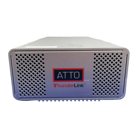
ATTO Technology XstreamCORE ET 8200 User manual

ATTO XstreamCORE® ET 8200
40-Gigabit 2-Port Ethernet to 12-Gigabit 4-Port SAS Storage Controller
ATTO XstreamCORE® ET 8200T
40-Gigabit 2-Port Ethernet to 12-Gigabit 4-Port SAS Tape Controller
Installation and Operation Manual
© 2020 ATTO Technology, Inc. All rights reserved. All brand
or product names are trademarks of their respective holders.
No part of this manual may be reproduced in any form or by
any means without the express written permission of ATTO
Technology, Inc.
1/2020 .. PRMA-0481-000

Table of Contents
1ATTO XstreamCORE 8200 Overview ..........................................................................................................................................5
ATTO XstreamCORE ET 8200/8200T features, benefits ........................................................................................................................5
ATTO XstreamCORE ET 8200/8200T......................................................................................................................................................6
Dimensions........................................................................................................................................................................................6
Cooling and airflow ...........................................................................................................................................................................6
Power ................................................................................................................................................................................................6
Ethernet data ports...........................................................................................................................................................................6
SAS/SATA ports .................................................................................................................................................................................6
Management ports............................................................................................................................................................................6
LED indicators....................................................................................................................................................................................7
2
Install the XstreamCORE
...............................................................................................................................................................8
Unpack the packing box; verify contents ..........................................................................................................................................8
Install the XstreamCORE ...................................................................................................................................................................8
Installation and Removal of Power Supply Modules.........................................................................................................................9
Discover the IP address with QuickNAV (Windows and Linux) .........................................................................................................9
Internet Explorer setup .....................................................................................................................................................................9
Begin initial configuration .................................................................................................................................................................9
Security Certificates ........................................................................................................................................................................10
3
Configure the XstreamCORE
........................................................................................................................................................12
Preliminary steps.............................................................................................................................................................................12
Port configurations..........................................................................................................................................................................12
Modify passwords ...........................................................................................................................................................................12
4
Map Devices
.............................................................................................................................................................................13
XstreamCORE mapping ...................................................................................................................................................................13
SAS/SATA device mapping ..............................................................................................................................................................13
Drive Map DirectorTM ......................................................................................................................................................................13
Mapping Devices with SMP.............................................................................................................................................................13
CLI view of mapped drives ..............................................................................................................................................................15
5XstreamCORE Discovery/Target Authentication Configuration ...............................................................................................17
XstreamCORE iSCSI Best Practices ..................................................................................................................................................17
Discovery Target Visibility ...............................................................................................................................................................17
Discovery CHAP ...............................................................................................................................................................................17
Target Access Control......................................................................................................................................................................18
Target CHAP ....................................................................................................................................................................................18
6Initiator Configuration ............................................................................................................................................................19

Linux ....................................................................................................................................................................................................19
Prerequisites ...................................................................................................................................................................................19
Initiator Setup Instructions .............................................................................................................................................................19
Configure the Data Ports.................................................................................................................................................................19
LTFS Setup for Tape Devices ...........................................................................................................................................................19
Discover XstreamCORE Targets.......................................................................................................................................................19
Configure Target CHAP....................................................................................................................................................................20
Connect to the Target .....................................................................................................................................................................20
LTFS Partition (Tape devices only)...................................................................................................................................................21
Disconnect from the Target ............................................................................................................................................................21
Windows..............................................................................................................................................................................................21
Prerequisites ...................................................................................................................................................................................21
Setup Instructions ...........................................................................................................................................................................21
LTFS Setup for Tape Devices ...........................................................................................................................................................22
Discover XstreamCORE Targets.......................................................................................................................................................22
Discovery CHAP ...............................................................................................................................................................................22
Connect to the Target .....................................................................................................................................................................23
CHAP................................................................................................................................................................................................23
Using iSCSI PowerShell Module.......................................................................................................................................................23
Disconnect from a Target................................................................................................................................................................24
Advisements ........................................................................................................................................................................................24
Jumbo Frames .................................................................................................................................................................................24
Network Configuration....................................................................................................................................................................24
7
Remote Monitoring, Management
...............................................................................................................................................25
SNMP-based monitoring
.........................................................................................................................................................................26
SNMP Agent Setup ..........................................................................................................................................................................26
SNMP Client Setup ..........................................................................................................................................................................26
Email messages perform error notification.........................................................................................................................................28
Redfish and Swordfish monitoring
............................................................................................................................................................28
8
Update Firmware
.......................................................................................................................................................................29
Using XstreamVIEW™......................................................................................................................................................................29
Using SFTP .......................................................................................................................................................................................29
9
Interface Options
.......................................................................................................................................................................30
Using XstreamVIEW™ System Manager
....................................................................................................................................................30
Opening an XstreamVIEW™ session................................................................................................................................................30
Using the serial port
................................................................................................................................................................................31

Using the USB port
.................................................................................................................................................................................31
Using SSH
..............................................................................................................................................................................................32
Making an SSH connection..............................................................................................................................................................32
Appendix A Cabling .........................................................................................................................................................................33
SAS/SATA connections.........................................................................................................................................................................33
Ethernet Data Connection...................................................................................................................................................................33
Ethernet management connection .....................................................................................................................................................33
Serial port connection .........................................................................................................................................................................34
USB cable connections ........................................................................................................................................................................34
Appendix B CLI Provides ASCII-based Interface ...............................................................................................................................35
CLI error messages...............................................................................................................................................................................36
CLI summary reference
...........................................................................................................................................................................36
Command explanations
...........................................................................................................................................................................40
Appendix C Standards and Compliances..........................................................................................................................................48
Regulatory Notices
.................................................................................................................................................................................48
FCC Notices (US only) ......................................................................................................................................................................48
Compliance with ICES-003...............................................................................................................................................................48
Compliance with EN Regulations ....................................................................................................................................................48
Appendix D Warranty Information ..................................................................................................................................................50
ATTO Technology, Inc. limited warranty .........................................................................................................................................50

1ATTO XstreamCORE 8200 Overview
The ATTO XstreamCORE ET 8200/8200T is an accelerated protocol conversion appliance that connects multiple shelves of SAS and
SATA JBOD, JBOF or RAID storage and SAS tape storage and virtualizes it to an Ethernet SAN Connection.
The ATTO XstreamCORE ET 8200/8200T allows IT
departments to design storage systems with the flexibility to
use standard interface off-the-shelf SAS storage hardware
with increased bandwidth and low latency levels that
improve performance and response. As a Data Center
building block, the ET 8200/8200T allows IT managers to build
their storage solution on their terms, avoiding vendor lock-in
with modularity at each layer. Use the ET 8200/8200T to
aggregate, virtualize and share storage with the knowledge
that it has undergone qualifications with industry leading
storage and network infrastructure products. Integrate the ET
8200/8200T into IT infrastructures to provide lower
operational costs through the use of tools like Drive Map
Director™ and XstreamVIEW™.
ATTO XstreamCORE ET 8200/8200T features, benefits
The ATTO XstreamCORE ET 8200/8200T is a 40-Gigabit
Ethernet to 12-Gigabit SAS storage controller configured with
two independent 40Gb Ethernet ports and four 12Gb x4 mini-
SAS connectors.
Designed to integrate industry-leading performance and SAN
capabilities into the future generation of storage solutions,
the XstreamCORE ET 8200/8200T uses a high-performance
architecture suited for OEMs looking to incorporate SAS or
SATA disk, tape or flash storage devices in their Ethernet
network. The 8200/8200T passes through raw drives to host
operating systems.
Two independent 40Gb Ethernet QSFP+ ports which auto-
negotiate to 40Gb or 10Gb Ethernet
Dual Power Supplies
Integrated xCORE Acceleration Processor
Data Mover technology (not supported on the ET 8200T)
Integrated eCORE Offload Processor
Supports iSCSI Extensions for RDMA (iSER)
Supports accelerated iSCSI over TCP/IP
Four independent 12Gb SAS/SATA x4 mini-SAS HD
connectors which auto-negotiate to 3Gb, 6Gb or 12Gb SAS
and 3Gb or 6Gb SATA
Automatic LUN Mapping & Management
Patented Drive Map Director™reduces operating expense
by auto-configuring storage
XstreamVIEW™ integrated management console for
remote configuration, management and diagnostic
capabilities
Supports SAS and SATA SSDs (not supported on the ET
8200T)
Supports SAS and SATA hard disk drives (not supported on
the ET 8200T)
Supports SAS tape drives & SATA optical drives
SpeedWrite™ technology improves write performance to
tape drives by up to 20% over SAS tape drives connected via
SAS HBAs
Performance note:
The XstreamCORE ET 8200/8200T supports both iSER and iSCSI over Ethernet. iSER runs over RDMA eliminating the
TCP/IP stack so it is much more efficient and provides higher throughput with deterministic latency. iSCSI runs over TCP/IP and will have
higher latency with slower performance than iSER.

ATTO XstreamCORE ET 8200/8200T
The ATTO XstreamCORE ET 8200/8200T is a high-performance storage controller that adds 40-Gigabit Ethernet connectivity to 12-
Gigabit SAS or SATA storage devices.
The XstreamCORE ET 8200/8200T is available in an industry-
standard 1U form factor and includes rack-mount hardware
for easy integration into 19” racks.
Dimensions
Width: 17.3 inches
Length: 9.9 inches
Height: 1.74 inches (1U)
Weight: approximately 10 pounds
Cooling and airflow
Operating temperature: 5-40 °C external
Humidity: 10-90% non-condensing
Air enters from the front and is exhausted out the connector
side. Ambient air near the inlets should not exceed 40°C. The
unit automatically stops operation if the temperature goes
beyond this threshold.
Do not block the enclosure’s vents. The
XstreamCORE does not allow data transfer if overheating
occurs.
Power
The ET 8200/8200T features two hot swappable power
supplies and can be operated with only a single power supply
inserted. Each power supply has a standard IEC320 power
receptacle and cooling fan. The power requirements of the
ATTO XstreamCORE ET 8200/8200T plus the power draw of
other equipment in the rack must not overload the supply
circuit and or wiring of this rack.
Input voltage: 120v operation –input 90-132 VAC 1A, 47-63
Hz 240v operation –input 180-264 VAC 1A, 47-63 Hz.
Ethernet data ports
The dual independent 40Gb/s Ethernet ports connect the
XstreamCORE ET 8200/8200T to Ethernet hosts using optical
QSFP+ connectors or QSFP direct connect copper cables.
Make sure all cables are anchored securely at both ends with
the proper connectors.
Ethernet data ports will connect an uplink to a
fabric switch or use fan-out cables that break up the 40GbE into
multiple 10GbE connections.
SAS/SATA ports
The 12Gb/s SAS/SATA connectors (16 PHYs total) connect
storage devices into the Storage Area Network (SAN) using
mini-SAS HD cable plug connectors.
Management ports
Management is provided using the dual 100/1000BASE-T
Ethernet ports accessible from the RJ-45 connectors labeled
'Ethernet', or the RS-232 command line interface from the RJ-
45 connector labeled 'Serial'. The ET 8200/8200T has a USB
2.0 port using a USB type B connector, implementing a
command line interface (CLI) over USB.
Only one command line interface (either RS-232 or
USB) can be active at one time.

LED indicators
LED indicators can be viewed from the connector side and the
front side of the XstreamCORE ET 8200/8200T.
LEDs on the connector side are:
Power Supplies: One LED for each supply. Blue indicates on
and ready. Blinking blue indicates power is applied but power
supply is not on. Blinking Red indicates an unplugged or failed
power supply.
Ready/Alert: Bi-color shared LED lit green means ready,
yellow indicates an alert condition.
Ethernet management port: The green left LED on the RJ45
connector indicates speed, while the right green LED
indicates an active link/activity.
Ethernet data port: A lit green LED indicates link, and OFF
means no link. Port LEDs are located below the QSFP+
connectors.
SAS/SATA device: SAS LEDs are located below the mini-SAS
HD connector. A lit green LED indicates a link has been
established on at least one PHY, and OFF means there are no
links.
LEDs on the faceplate are:
Power Supplies: One LED for each supply (PSA and PSB).
Green indicates on and ready while amber indicates an
unplugged or failed supply.
If both power supplies are on and both LEDs are
yellow at the same time, this indicates a bad status connection.
Status harnesses may not be connected.
Power: A lit green LED indicates power has been turned ON
to the storage controller.
Ready: A lit green LED indicates ready and OFF to show not
ready.
Alert: A lit yellow LED indicates an alert condition.
Ethernet Data Port Activity: A lit green port activity LED
indicates traffic on the port, and OFF indicates no port
activity.
Ethernet Data Port Speed: A bi-color port speed LED is lit as
follows: Green = 40Gb/s, Yellow = 10Gb/s, and OFF = no link
or 1GbE.
SAS/SATA Device Activity: A lit green LED for each SAS
connector indicates port activity on at least one PHY in the
connector, and OFF means no port activity.
Exhibit 1 ET 8200/8200T Connectors, LEDs and power receptacle on the connector side.
Exhibit 2 ET 8200/8200T LEDs on the faceplate.

2Install the XstreamCORE
If you have not already completed the instructions on the Quick Start page packed with your XstreamCORE, use the following
instructions to install the XstreamCORE.
Unpack the packing box; verify contents
The XstreamCORE.
oRecord the serial number, default username, and
default password located on the bottom of the unit:
S/N: __________________________________
Default Username: ______________________
Default Password: _______________________
The username and password are needed to access
XstreamVIEW, Telnet, and FTP services via the
Ethernet management ports.
During the first login to XstreamVIEW or Telnet, the
XstreamCORE will prompt you to change the unit’s default
password.
Power cords
“L” brackets for mounting in a 19” rack
Ethernet cable
RS-232 cable
Install the XstreamCORE
1. Place the XstreamCORE on a stable flat surface or install
it into a standard rack.
2. If installing into a rack, attach the brackets to both sides
of the XstreamCORE enclosure. Then install the
XstreamCORE assembly horizontally within the rack so it
does not reduce the air flow within the rack.
3. Connect the host computer by connecting the cable to
Ethernet data port 1 or 2.
4. Connect target devices by connecting SAS cables to SAS
connector A, B, C or D.
5. Power up the target devices.
6. Connect the Ethernet port to your network.
7. Connect the AC power cords from the XstreamCORE to
the proper AC source outlets.
Power is automatically supplied to the ET 8200
when plugged into an AC outlet.
The power source must be connected to a
protective earth ground and comply with local electrical codes.
Improper grounding may result in an electrical shock or
damage to the unit. Also, be aware that this unit is powered on
once a power source is connected. Make sure the power supply
module is fully inserted before applying power. Failure to do so
may cause injury or damage the unit.
If you are using a rack:
1. Properly ground the XstreamCORE to the rack
equipment. The earth ground connection must be
maintained.
2. The power requirements plus the power draw of the
other equipment in the rack must not overload the
supply circuit and/or wiring of the rack.
3. Wait for the XstreamCORE Ready LED to light, indicating
that the XstreamCORE has completed its power-on self-
test sequence.
Exhibit 3 Attach rack mounting brackets to XstreamCORE
Exhibit 4 Install XstreamCORE into a rack.
Exhibit 5 XstreamCORE ET 8200/8200T, LEDs, power receptacle and ports

Installation and Removal of Power Supply Modules
Handle and latch should be on top.
Remove the power source before removing the
power supply module. Failure to do so may cause injury or
damage the unit.To remove a power supply module, first
remove the power cord.
1. Press the side latch inward and pull out on the handle.
2. To install a power module, insert module until you hear
the latch click.
3. Install power cord.
Discover the IP address with QuickNAV (Windows
and Linux)
The XstreamCORE is initially configured with DHCP
enabled. It is best if you have access to a DHCP server.
For Linux, make sure the file permissions are set to
executable after downloading.
1. Power on your system and log in as a user with proper
administrative privileges from the computer attached to
the XstreamCORE Ethernet management port on the
same domain.
2. Go to www.atto.com.
3. Select Downloads from the Support menu.
4. Register or log in if previously registered.
5. Select Storage Controllers from the product list.
6. Select your model.
7. From the table, find your Operating System.
8. Click on the entry for the QuickNAV™ utility.
9. Select a download destination and allow the download to
complete. Double-click the downloaded QuickNAV™ file
to install onto your operating system, and launch the
program.
10. Select the network interface for QuickNAV discovery.
Click Next.
11. Locate the XstreamCORE with the serial number
recorded earlier.
12. Highlight the serial number.
13. Click Next.
If a DHCP server is available on your network, an address is
assigned automatically by the server. Note the assigned
address: _____________________________________, and
click on Launch Browser. Your browser points to the ATTO
XstreamVIEW welcome screen. If you use Internet Explorer as
a browser, continue on to Internet Explorer setup below. If
not, continue on to Initial Configuration.
If you do not have a DHCP server, click on Next, get an IP
address and subnet mask from your network administrator,
type it into the area provided, and click on Next.
XstreamCORE supports the Google Chrome, Firefox
and Microsoft Edge browsers
14. Click on Reboot Now. Wait up to two minutes for the
XstreamCORE Ready LED to light indicating the
XstreamCORE has completed its power-on self-test
sequence. Launce your browser and navigate to the IP
address received from your network administrator. Your
browser points to the ATTO XtreamVIEW™ welcome
screen. If you use Internet Explorer as a browser,
continue on to Internet Explorer setup below. If not,
continue on to Initial Configuration.
Internet Explorer setup
1. Open your browser
2. Go to the browser toolbar and select Tools.
3. Select Internet Options.
4. In the Internet Options screen, select the Security tab.
5. Click on the Trusted Sites icon.
6. Click on the Sites button.
7. Uncheck the Require server verification
check box.
8. In the text box Add this web site to the zone, add the IP
address of the appliance. You may use wild cards.
9. Click Close.
10. At the bottom of the Internet Options dialog, click OK.
Begin initial configuration
1. The XstreamVIEW™ interface welcome screen appears.
Click on Enter Here.
2. Type in the user name and password.
The default user name and password values
can be
found on the bottom of the unit.
The user name is case insensitive and the password is case
sensitive. It is best practice to change the default user name
and password. Refer to Modify passwords.
During the first login to XstreamVIEW or SSH, the XstreamCORE
will prompt you to change the unit’s default password. After
the new password is accepted, the unit will reboot. Wait up to
two minutes for the XstreamCORE Ready LED to light indicating
the XstreamCORE has completed its power-on self-test
sequence. Re-launch your browser and navigate to the correct


IP address. Your browser points to the ATO XstreamVIEW™
welcome screen. Type in the user name and password.
3. The XstreamVIEW™ status page appears. Continue to
Map Devices.
Security Certificates
Certificate, Keys, and PEM file
The XstreamCORE controller uses a certificate (aka. Public
key) that is provided to devices on a network to authenticate
the controller to them. The HTTPS, SSH, and SFTP servers in
the controller expects to have access to a PEM (Privacy
Enhanced Mail) file containing the keypair (certificate and its
associated private key) necessary to provide access. The
initial keypair PEM file has been generated by the controller.
Note that the private key is only seen by the controller.
Keypair regeneration
The PEM file containing the keypair is regenerated by the
controller if:
1. It expires. This will be noted in the XstreamCORE event
log. Additionally, the approaching expiration of the
keypair is logged one month prior to its expiration.
2. The IP configuration of an Ethernet port changes. The
certificate used on the controller uses the IP
configurations of the Ethernet ports (but not the DNS
name of the controller). If an Ethernet port IP
configuration changes, the keypair will be regenerated to
reflect the change.
3. User-provided certificate attributes change.
In all cases, since it is the controller that generates the
keypair, the certificate within will be self-signed. This will
result in a client web browser warning advisement when a
connection attempt is made to the controller.
Even if an externally signed certificate is present on
the XstreamCORE, a self-signed certificate will be generated to
replace it if the conditions met above are met.
Uploading a keypair PEM file
If a self-signed certificate is not desirable, an externally-
signed certificate and its associated private key can be
uploaded to the controller. The file containing this keypair
must meet several requirements:
1. It must be named httpspem.pem.
2. It must be in the PEM format.
3. The contents of the file must include both the certificate
and the private key.
4. It must not be encrypted (if generated via OpenSSL's
"req" command, specify "-nodes").
5. The private key must be an RSA private key.
6. The certificate must be SHA256 signed.
7. The certificate must have the same attributes as the
controller displays in the “get HttpsCertParams”
command (see below).
The file format should appear as follows (note that the actual
contents have been abbreviated):
-----BEGIN PRIVATE KEY-----
MIIEvgIBADANBgkqhkiG9w0BAQEFAASCBKgwggSkAgEAAoIBA
QDaJU8liMAIZREs
… <snip>
uU0m3t4sxrOlF5WarwTYQWKE
-----END PRIVATE KEY-----
-----BEGIN CERTIFICATE-----
MIIDIjCCAgqgAwIBAgIJANYizZ6isr/gMA0GCSqGSIb3DQEBCwUA
MDoxCzAJBgNV
… <snip>
/GAqJDXDoFDpHrHGEXtOi9AP1VKxREo+J/L9eb+CuOE/EPFaHlM
=
-----END CERTIFICATE-----
Keypairs may be uploaded via the “Certificate Management”
page of the XstreamVIEW interface.
CLI commands available for the user
1. HTTPSCertInfo: This command displays certificate
information to the console, including IP addresses
associated with the keypair PEM file, the expiration date,
attributes, and algorithms used. Example output:
Certificate:
Data:
Version: 3 (0x2)
Serial Number:
d6:22:cd:9e:a2:b2:bf:e0
Signature Algorithm: sha256WithRSAEncryption
Issuer: ST = NY, L = Getzville, O = AttoTechnology
Validity
Not Before: Feb 4 18:32:13 2019 GMT
Not After : Feb 4 18:32:13 2020 GMT
Subject: ST = NY, L = Getzville, O = AttoTechnology
X509v3 extensions:
X509v3 Basic Constraints:
CA:FALSE
X509v3 Key Usage:
Digital Signature, Non Repudiation, Key Encipherment
X509v3 Subject Alternative Name:
IP Address:10.40.0.31
-----BEGIN CERTIFICATE-----

MIIDIjCCAgqgAwIBAgIJANYizZ6isr/gMA0GCSqGSIb3DQEBCwUA
MDoxCzAJBgNV
<snip>
-----END CERTIFICATE-----
2. HttpsCertParams: Displays and configures the
certificate’s attributes, including State (ST), Locality (L),
and Organization (O) attributes (as shown in the example
above). These attributes may also be set via the
Certificate Management page in the XstreamVIEW web
interface.
Exhibit 6 Certificates and PEM file upload –useful for setting
certificate attributes or uploading a PEM file if a self-signed
certificate is not desirable.

3Configure the XstreamCORE
To configure the XstreamCORE, use the ATTO XstreamVIEW™ System Manager GUI. Default values are appropriate for most
configurations, but may be modified. In-band configuration is also available, contact ATTO support for details.
The best way to access the XstreamCORE to view and change
settings is to use ATTO XstreamVIEW™ System Manager, a
browser-based graphical interface. Other methods are also
available. Refer to Interface Options
Help is available from within XstreamVIEW™ by clicking on
the text indicating each setting. For more information on any
of these parameters, refer to the specific CLI command in
Command explanations.
To change mapping, refer to Map Devices
To use Email notification or SNMP, refer to Remote
Monitoring, Management.
You may make changes to several pages before going to the
Restart page and restarting the XstreamCORE to save the
changes.
Preliminary steps
1. If you are not already in the XstreamVIEW™ interface,
type the IP address of your XstreamCORE in a standard
browser as found in Using
XstreamVIEW™ System
Manager, click Enter Here,
type in your user name and
password, and click OK.
2. The Status page appears.
Check default settings to
ensure they are appropriate
for your configuration. Use
the individual pages listed on
the side menu to make
setting changes or to
configure features.
Port configurations
1. Follow the Preliminary steps.
2. There are two different ways to get to a specific data
port/management port page:
a) Select the port you wish to configure from the
banner at the top of the home page. This will take
you directly to that port’s configuration page.
b) Select the “Ethernet” page from the left menu. This
takes you to a page with tabs for each Ethernet port.
3. Select the parameters you wish to change.
4. Click Submit.
5. If you have completed all changes for this session, go to
the Restart page and restart the Ethernet storage
controller.
Modify passwords
1. Follow the
Preliminary steps.
2. From the side menu
select Controller.
The storage
controller
Configuration page
is displayed.
The Administrator user
name that you are
currently logged in with
and the current read
only user name, if present, are displayed in their text boxes.
3. Enter the Administrator (Admin) password where
indicated.
4. Enter appropriate information into the New Admin
Password, Confirm New Admin Password or New Read
Only Password and Confirm New Read Only Password
text boxes.
5. Click Submit.
6. If you have completed all changes for this session, go to
the Restart page and restart the XstreamCORE.

4Map Devices
After getting an IP address and logging into the ATTO XstreamVIEW™ System Manager, you have options to map devices so that the
XstreamCORE can provide access to storage on your network.
The ATTO XstreamCORE allows SAS/SATA devices to
participate in an Ethernet fabric. Ethernet and SAS/SATA use
different models to address devices. The XstreamCORE
translates between these addressing models.
XstreamCORE mapping
On the network, the XstreamCORE presents a number of
targets, each identified by an iSCSI IQN. The IQN consists of
two parts: a fixed portion based on the product name and
serial number, and a target name. Target names are assigned
automatically as SAS expanders supporting SMP are
discovered. A target node with the 'default' suffix is always
created containing a LUN for each discovered SAS/SATA
device. See Drive Map Director. Targets can also be created
manually using the XstreamVIEW™ System manager.
Each target node can be accessed by one or more network
portals. Each network portal is identified by its IP address and
listening TCP port. All target names and available target
portals are transmitted to a host using the standard iSCSI
discovery mechanism.
SAS/SATA device mapping
SAS/SATA devices connected to the XstreamCORE are viewed
as Ethernet LUNs to the host computer.
The ATTO XstreamVIEW™ interface displays the current
mapping information for SAS/SATA devices.
SCSI commands sent to offline devices
are rejected.
Drive Map DirectorTM
Drive Map Director uses SMP to provide a predictable
mapping structure for devices attached to the XstreamCORE
ET 8200. To use this feature, drive enclosures must support
SAS expanders using the SMP protocol such as HP
StorageWorks SAS JBODs.
Mapping Devices with SMP
Drive Map Director assigns an Ethernet target number to
each shelf of storage and an Ethernet LUN is reserved for
each slot within the enclosure. This numbering scheme is
static and will remain with the shelf and slot location
whenever a drive or shelf is added or removed. This allows
maps to remain the same when shelves or drives need to be
swapped out due to failure and remain consistent during
power cycles of the XstreamCORE.
1. If you are not already in the XstreamVIEW™ interface,
type the IP address of your XstreamCORE in a standard
browser as found in Using XstreamVIEW™ System
Manager, click Enter Here, type in your user name and
password, and click OK.
2. The Status page appears.
3. From the XstreamVIEW™ main menu, click on the
Manual Target Management menu on the left side of
the screen. A list of available targets appears in the
Configure iSCSI Targets box.
4. Click on the Device Maps link next to the target to be
configured. The default target is fixed; it cannot be
configured or deleted.
5. The Mapping page appears. If your storage supports
SMP, the XstreamVIEW™ System Manager will display
mapping information for your devices.

Exhibit 7 Configure iSCSI Targets

CLI view of mapped drives
This is an alternative view (via the CLI) for examining how drives are mapped through the XstreamCORE.
Note gap in LUNs, reserved for drives not currently installed in enclosure
In this example, a single enclosure was discovered with 24 drive slots. A target with an IQN suffix of 50014380052bb03e was
created for this enclosure plus a default target created containing an entry for each drive. When additional enclosures are attached
a new target will be created for the enclosure containing one entry for each drive in that enclosure. Each new drive will also be
added to the default target.
routedisplay
30
;Target Name LUN Device Address LUN VendorID ProductIDSerialNum
;===============================================================================
50014380052bb03e0 Controller
50014380052bb03e 1 5000c5001cb9d6b90 HP EG0300FAWHV 3SE19E9X00009023NNJZ
50014380052bb03e 2 5000c5001cb969150 HP EG0300FAWHV 3SE1AAG900009023UPVC
50014380052bb03e 3 5000c5001cb3fd450 HP EG0300FAWHV 3SE1B6AL00009022K5E8
50014380052bb03e 4 5000c5001cb3b7890 HP EG0300FAWHV 3SE1B7HC00009022L2YV
50014380052bb03e 5 5000c5001cb38ed50 HP EG0300FAWHV 3SE1B8BK00009022KBRX
50014380052bb03e 16 5000c5001cbaf1990 HP EG0300FAWHV 3SE1ABD500009023TBAX
50014380052bb03e 17 5000c5001cab46c90 HP EG0300FAWHV 3SE19GEB00009022KVBW
50014380052bb03e 18 5000c5001cba0a810 HP EG0300FAWHV 3SE16SGD00009023V6JN
50014380052bb03e 19 5000c5001cb961e50 HP EG0300FAWHV 3SE1AX4G00009023M8VU
50014380052bb03e 20 5000c5001cbb29510 HP EG0300FAWHV 3SE1BGWX00009023RX5P
50014380052bb03e 21 5000c5001cbae9b10 HP EG0300FAWHV 3SE1B7GL00009023TMEE
50014380052bb03e 22 5000c5001cb93fa50 HP EG0300FAWHV 3SE1AYA600009023RRL1
50014380052bb03e 23 5000c5001cb91a950 HP EG0300FAWHV 3SE1AZBP00009023RS03
50014380052bb03e 24 50014380052bb03e0 HP D7200 SAS AJ941A CN8931000N
default 0 Controller
default 1 5000c5001cb9d6b90 HP EG0300FAWHV 3SE19E9X00009023NNJZ
default 2 5000c5001cb969150 HP EG0300FAWHV 3SE1AAG900009023UPVC
default 3 5000c5001cb3fd450 HP EG0300FAWHV 3SE1B6AL00009022K5E8
default 4 5000c5001cb3b7890 HP EG0300FAWHV 3SE1B7HC00009022L2YV
default 5 5000c5001cb38ed50 HP EG0300FAWHV 3SE1B8BK00009022KBRX

default 6 5000c5001cbaf1990 HP EG0300FAWHV 3SE1ABD500009023TBAX
default 7 5000c5001cab46c90 HP EG0300FAWHV 3SE19GEB00009022KVBW
default 8 5000c5001cba0a810 HP EG0300FAWHV 3SE16SGD00009023V6JN
default 9 5000c5001cb961e50 HP EG0300FAWHV 3SE1AX4G00009023M8VU
default 10 5000c5001cbb29510 HP EG0300FAWHV 3SE1BGWX00009023RX5P
default 11 5000c5001cbae9b10 HP EG0300FAWHV 3SE1B7GL00009023TMEE
default 12 5000c5001cb93fa50 HP EG0300FAWHV 3SE1AYA600009023RRL1
default 13 5000c5001cb91a950 HP EG0300FAWHV 3SE1AZBP00009023RS03
default 14 50014380052bb03e0 HP D7200 SAS AJ941A CN8931000N

5XstreamCORE Discovery/Target Authentication Configuration
If you are not already in the XstreamVIEW™ interface, type the IP address of your XstreamCORE in a standard browser as found in
using XstreamVIEW System Manager, click Enter Here, type in your user name and password, and click OK. The Status page should
now appear.
XstreamCORE iSCSI Best Practices
It is recommended that the XstreamCORE ET 8200 is used on an isolated physical, lossless network when using iSCSI
When using the XstreamCORE ET 8200 each data port must be assigned to an independent subnet in order to achieve full
bandwidth. The XstreamCORE’s Ethernet management ports must also be assigned to independent subnets
Spanning-tree protocol (STP) should be disabled on the switch ports being used for iSCSI traffic. This would mean ports connected
to the 8200 and each iSCSI initiator
If you do need STP enabled it is recommended that you enable the STP FastPort feature on your switch
Flow control (XON/XOFF) should be enabled on the switch ports and the iSCSI initiators
Recommend disabling UNICAST storm control on your switch
It is recommended that you USE broadcast and multicast storm control on your switch
Jumbo frames (large MTU’s) should be enabled on all switch ports, the iSCSI initiators, and the 8200 data ports for optimal
performance
If Virtual LAN (VLAN) is required, ATTO recommends configuring VLAN on your switch. A switch created VLAN is a broadcast
domain, which helps separate traffic on switch ports
Recommended for larger networks, when there is a lot of broadcast traffic, or when using similar protocols like iSCSI
Discovery Target Visibility
To prevent initiators from discovering a particular
XstreamCORE target, Access Control must be enabled for that
target (see Target Access Control below). Once enabled, only
initiators in the list of Allowed Initiators will be able to
discover that target. If Access Control is disabled for a target,
any initiator with access to the same network the
XstreamCORE is located on and which has the correct
discovery CHAP credentials (if any) will be able to discover
and connect to that target.
Discovery CHAP
1. Click on Manual Target Mgt on the left hand side of the
screen.
2. Under Configure iSCSI Targets, click on the iSCSI CHAP
link next to Discovery.
3. In the iSCSI CHAP Configuration page, select the type of
CHAP you wish to use for discovery sessions from the
drop-down list next to iSCSI CHAP, and click Submit.
The following steps only apply when using one-way or two-
way CHAP for discovery:
4. (Two-way CHAP only) Fill in the iSCSI CHAP Out Account
Name and CHAP Out Secret.
5. Fill in the iSCSI CHAP In Account Name and CHAP In
Secret.
6. Click Submit.

Target Access Control
1. Click on Manual Target Mgt on the left hand side of the
screen.
2. Under Configure iSCSI Targets there is a list of all
XstreamCORE targets. Click on the Access Control link
next to the target you wish to configure.
3. Click on the enabled or disabled button next to Access
Control to turn Access Control on or off for this target,
and click Submit.
If Access Control is disabled, any initiator that can
discover this target will be able to connect to it.
The following steps only apply when Access Control is
enabled for this target:
1. The Allowed Initiators list displays the IQN's of initiators
that are permitted to connect to this target. To add an
initiator select its IQN from the List of Initiators on the
left, then click the Add >> button.
If an initiator's IQN is not listed, you can add it by
typing it in under Create New Initiator Name at the bottom of
the page, and clicking Create.
2. To remove an initiator from the Allowed Initiators list
select its IQN from the list on the right, and click on the
<< Remove button.
3. When finished adding/removing initiators to/from the
Allowed list, click Submit.
Target CHAP
This section only applies if Access Control is enabled for the
target.
1. Click on Manual Target Mgt on the left hand side of the
screen.
2. Under Configure iSCSI Targets there is a list of all
XstreamCORE targets. Click on the iSCSI CHAP link next to
the target you wish to configure.
3. In the iSCSI CHAP Configuration page, select the type of
CHAP you wish to use when connecting to this target
from the drop-down list next to iSCSI CHAP, and click
Submit.
The following steps only apply when using one-way or two-
way CHAP to connect to this target:
4. (Two-way CHAP only) Fill in the CHAP Out Secret.
5. Under Initiator Account is a list of initiator IQN's which
are permitted to connect when Access Control is enabled
for this target. If the IQN you wish to change the secret
for is not listed, you will need to add it to the target
through its Access Control page (see Target Access
Control).
6. Fill in the CHAP In Secret next to the initiator IQN you
wish to set.
The CHAP Out Account Name for targets will always
be the full IQN (including the XstreamCORE product name and
serial number) of that target - it is not configurable.
7. Click Submit.
These settings can also be modified using the
command line interface. For more information, refer to the
AccessControl, AccessEntry, iSCSICHAP and iSCSICHAPSecret
commands in Appendix B

6Initiator Configuration
It is recommended that the user establish multiple sessions to the XstreamCORE ET 8200 from each host. Also, the user should set up
one session per “Data Port” to each of the ports of the network cards. This ensures that if a link goes down a session can be restarted.
Linux
Prerequisites
1. Server with a 40GbE adapter running a supported Linux
kernel.
2. XstreamCORE data ports configured and connected to
the same network as the 40GbE adapter.
Initiator Setup Instructions
If any command fails with permission denied, prefix
the command with sudo, and try again.
Install the iSCSI Initiator Utilities
For systems using apt package management, enter the
following command:
apt install open-iscsi
For systems using yum package management, enter the
following command:
yum install iscsi-initiator-utils
To determine which package management software
is used by your Linux distribution, use the following command:
which yum
If the output is similar to /bin/yum, this distribution uses yum,
otherwise it uses apt.
Configure the Data Ports
1. For iSCSI applications, the in-box driver should be used to
connect the 8200 to the host.
2. For iSER (iSCSI extensions for RDMA) applications, load
the appropriate driver that supports RDMA on your host
installed NIC.
3. Ports may be auto-configured if connected to a network
with DHCP. Otherwise, they will need to be assigned an
IP address using the ipconfig command.
If Ethernet ports are direct-connected to the
XstreamCORE without the use of a switch and both data ports
are used, the XstreamCORE data ports must not be on the same
subnet. The default subnet mask for the XstreamCORE is
255.255.0.0
4. Test the network connection using the ping command.
Note the IP address of the XstreamCORE data port and
then on the initiator, enter the following command:
ping ipaddress
ipaddress is the address of the XstreamCORE data
port.
Sample output:
PING 172.16.1.20 (172.16.1.20) 56(84) bytes of data.
64 bytes from 172.16.1.20: icmp_seq=1 ttl=64 time=0.144 ms
64 bytes from 172.16.1.20: icmp_seq=2 ttl=64 time=0.111 ms
64 bytes from 172.16.1.20: icmp_seq=3 ttl=64 time=0.116 ms
LTFS Setup for Tape Devices
If using tape devices in a LTFS setup, install Linear Tape File
System (LTFS) software provided by the tape device
manufacturer.
If using iSER with tape devices, set max sectors to 2048
before attempting to mount or create a LTFS partition. To do
this enter following two commands:
rmmod ib_iser
modprobe ib_iser max_sectors=2048
The ib_iser change is not persistent across reboots.
To make the changes persistent, you should add a kernel
module configuration file. This modification will take place
whenever the ib_iser module is started.
Create the file
/etc/modprobe.d/ib_iser.conf
Add the max sectors modification option the the file options
ib_iser max_sectors=2048
Discover XstreamCORE Targets
If one-way or two-way CHAP authentication has been
configured on the XstreamCORE for the discovery session,
open /etc/iscsi/iscsid.conf in a text editor and add or modify
the following lines:

discovery.sendtargets.auth.authmethod = CHAP
discovery.sendtargets.auth.username = username
discovery.sendtargets.auth.password = password
username and password must match the CHAP In
Account Name and CHAP In Secret configured on the
XstreamCORE for discovery. Both username and password are
case-sensitive.
If two-way CHAP authentication has been configured on the
XstreamCORE for discovery, also add or modify the following
lines in /etc/iscsi/iscsid.conf:
discovery.sendtargets.auth.username_in = username_in
discovery.sendtargets.auth.password_in = password_in
username_in and password_in must match the CHAP
Out Account Name and CHAP Out Secret configured on the
XstreamCORE for discovery. Both username_in and
password_in are case-sensitive.
You must log out of any current sessions and re-
perform discovery for the CHAP settings to take effect.
Discover XstreamCORE targets by entering the following
command:
iscsiadm -m discovery -t st -p ipaddress
ipaddress is the address of the XstreamCORE data
port to perform discovery through.
The command should return a list of all XstreamCORE targets
available to this initiator.
If an XstreamCORE target exists but is not returned
through discovery, check that this initiator is in the list of
Allowed Initiators for that target (see Target Access Control in
Section 5).
If "Login failed to authenticate with target" is returned, check
that the credentials set in /etc/iscsi/iscsid.conf match the
credentials configured on the XstreamCORE.
Configure Target CHAP
This section only applies when one-way or two-way CHAP
authentication has been configured on the XstreamCORE to
connect to a target. If not using CHAP, skip to Connect to the
Target.
1. Enter the following commands:
iscsiadm -m node -T target -o update -n
node.session.auth.authmethod -v CHAP
iscsiadm -m node -T target -o update -n
node.session.auth.username -v username
iscsiadm -m node -T target -o update -n
node.session.auth.password -v password
target must match the full target IQN returned by
the discovery command above. username must match the CHAP
In Account Name configured on the XstreamCORE for this
target. password must match the CHAP In Secret configured on
the XstreamCORE for this target. Both username and password
are case-sensitive.
2. (Two-way CHAP only) Enter the following commands:
iscsiadm -m node -T target -o update -n
node.session.auth.username_in -v username_in
iscsiadm -m node -T target -o update -n
node.session.auth.password_in -v password_in
target must match the full target IQN returned by
the discovery command above. username_in must match the
full target IQN returned by the discovery command above.
password_in must match the CHAP Out Secret configured on
the XstreamCORE for this target. Both username_in and
password_in are case-sensitive.
You must log out of any current sessions and re-
perform discovery for the CHAP settings to take effect.
Connect to the Target
1. (iSER only) Change the connection mode to iSER by
entering the following command:
iscsiadm -m node -T target -o update -n iface.transport_name -
v iser
target must match the full target name returned
from the discovery command above.
2. Log in to the target by entering the following command:
iscsiadm -m node -T target -p ipaddress -l
target must match the full target name returned
from the discovery command above. ipaddress is the address of
the XstreamCORE data port used in the discovery command
above.
You can verify the initiator is connected using the command
line interface's DisplayInitiators command (see Appendix B). If
using XstreamVIEW™, click on Advanced on the left hand side
of the screen, enter DisplayInitiators under Enter a CLI
command, and click Submit.
This manual suits for next models
1
Table of contents
Other ATTO Technology Controllers manuals

ATTO Technology
ATTO Technology FibreBridge 7500 User manual

ATTO Technology
ATTO Technology SC 5550E User manual

ATTO Technology
ATTO Technology ATTO XstreamCORE FC 7500 User manual

ATTO Technology
ATTO Technology ThunderLink Desklink FC 1082 User manual

ATTO Technology
ATTO Technology FastStream SC 5550 User manual