AUBO I Series User manual

USER MANUAL
AUBO-i3 & CB4
Please read this manual carefully before using the product.


User Manual
AUBO-i3 & CB4
Translate Version 4.5
Published by AUBO (Beijing) Robotics Technology Co, Ltd.
This manual is applicable to AUBORPE V 4.5. For details, please refer to the version information
section of this manual. Please check the actual product version information carefully before use to
ensure consistency.

The user manual will be checked and revised periodically, and the updated content will appear on the latest
version.
The information in this manual is subject to change without notice and should not be regarded as a
commitment by AUBO (Beijing) Robotics Technology Co., Ltd.
AUBO (Beijing) Robotics Technology Co., Ltd. assumes no responsibility for any errors or omissions in this
document. AUBO (Beijing) Robotics Technology Co., Ltd. assumes no responsibility for incidental or
consequential damages arising from use of this manual and products described herein.
Please read this manual before install or use.
Please keep this manual to read and as reference any time.
The pictures in this manual are for reference only, please refer to the actual product received.
Copyright © 2015-2018 AUBO All rights reserved

V4.5
©2015-2019 AUBO.All rights reserved. i
CATALOG
CATALOG................................................................................................................................I
PREFACE.............................................................................................................................VII
COMPONENTS OF AUBO-I3 ROBOT..........................................................................VIII
MORE INFORMATION...................................................................................................VIII
1. SAFETY .............................................................................................................................9
Introduction...................................................................................................................9
Warning Symbols in this Manual..................................................................................9
Safety Precautions.......................................................................................................10
General..............................................................................................................10
Terms and Conditions .......................................................................................10
Operator safety..................................................................................................14
Responsibility and standard ........................................................................................15
Hazard Identification ..................................................................................................17
Intended use ................................................................................................................18
Emergency situations ..................................................................................................19
Emergency stop device .....................................................................................19
Recovering from the emergency condition.......................................................20
Emergency move for joint ................................................................................20
Excessive force protection ................................................................................20
2. TRANSPORTATION AND PRECAUTIONS ..............................................................21
3. MAINTENANCE, REPAIR AND DISPOSAL.............................................................23
Maintenance and repair...............................................................................................23
Disposal.......................................................................................................................24
4. WARRANTIES................................................................................................................25
Product Warranty ........................................................................................................25
Disclaimer...................................................................................................................25
5. ROBOT HARDWARE COMPOSITION .....................................................................27
6. ROBOT INSTALLATION .............................................................................................29
Brief installation steps.................................................................................................29
Important safety instructions.......................................................................................29
Workspace of the Robot..............................................................................................30
Mechanical dimensions of manipulator............................................................30
Effective working range....................................................................................31

V4.5
©2015-2019 AUBO.All rights reserved. ii
Hardware Installation..................................................................................................32
The Manipulator Base.......................................................................................32
Manipulator Installation....................................................................................33
End-effector Installation .............................................................................................35
Mechanical structure size of end-effector flange..............................................35
Cable connection.........................................................................................................35
7. THE I SERIES STANDARD CONTROL BOX ...........................................................39
Introduction.................................................................................................................39
Electrical warnings and cautions ................................................................................40
Control box panel introduction ...................................................................................40
Control box front panel.....................................................................................41
Control box side panel ......................................................................................42
Control box back panel .....................................................................................45
Selection of working mode .........................................................................................46
Manual mode ....................................................................................................47
Linkage mode....................................................................................................47
8. INTERNAL ELECTRICAL INTERFACE ..................................................................51
Introduction.................................................................................................................51
Electrical warnings and cautions ................................................................................51
Control box communication interface ........................................................................52
Control box I/O power supply ....................................................................................53
Internal power supply .......................................................................................53
External power supply ......................................................................................53
Safety I/O....................................................................................................................54
Introduction.......................................................................................................54
Safety Tips ........................................................................................................54
Safety I / O function definition .........................................................................54
Default Safety Configuration............................................................................55
External Emergency Stop Input ........................................................................56
Safeguard stop Input .........................................................................................57
Reduce Mode Input...........................................................................................59
Safeguard stop Resert Input..............................................................................60
Enabling Device Input ......................................................................................61
Operational Mode Input..................................................................................62
Hand Guiding Enable Input ............................................................................62
System Stop Input...........................................................................................63
Robot Emergency Stop Output .......................................................................64
Robot Moving Output.....................................................................................65
Robot Not Stopping Output ............................................................................66
Reduced Mode Output ....................................................................................67
Not Reduced Mode Output .............................................................................68

V4.5
©2015-2019 AUBO.All rights reserved. iii
8.5.18 System Error Output .......................................................................................69
Internal I/O..................................................................................................................70
General I/O..................................................................................................................71
General purpose digital I/O interface................................................................71
Example ................................................................................................................................72
Analog I/O interface..........................................................................................74
Example ................................................................................................................................75
Clear alarm signal interface ..............................................................................76
Remote switch control I/O interface...........................................................................76
Remote power on ..............................................................................................77
Remote power off .............................................................................................77
Linkage Control I/O Interface.....................................................................................77
Robot Tool I/O Interface...........................................................................................79
9. GETTING STARTED.....................................................................................................82
Basic function introduction.........................................................................................82
Installing the robot system ..........................................................................................83
Power on the manipulator ...........................................................................................83
Preparation ........................................................................................................83
Power on System...............................................................................................84
Power off the manipulator ..........................................................................................85
Start system quick.......................................................................................................85
10. TEACH PENDANT.....................................................................................................86
Instruction .................................................................................................................86
Teach Pendant Operation Interface...........................................................................86
User login........................................................................................................86
Initial Interface................................................................................................87
Robot Movement Control ...............................................................................88
Robot Teaching User Interface..............................................................................................88
1 Currently logged in user.....................................................................................................89
2 Logout button.....................................................................................................................89
3 Software shut down button ................................................................................................89
4 Menu ..................................................................................................................................89
5 Robot 3D display window..................................................................................................90
6 Simulation/real control switch button................................................................................91
7 Step Mode Control.............................................................................................................91
8 Position control ..................................................................................................................91
9 Coordinate system..............................................................................................................93
9 User-defined coordinate system.........................................................................................93
10 Robot real-time status parameter display.........................................................................94
11 Target selection ................................................................................................................94
12 Orientation Control ..........................................................................................................94

V4.5
©2015-2019 AUBO.All rights reserved. iv
13 Joint axis control..............................................................................................................95
14 Zero Pose, Init Pose .........................................................................................................96
15 Motion speed control .......................................................................................................96
16 Date and time display.......................................................................................................96
17 Speed control ...................................................................................................................97
Robot I/O settings and status display........................................................................97
Controller I/O Tab...........................................................................................97
User I/O Tab....................................................................................................98
Tool I/O Tab ....................................................................................................98
Robot Setting Tab....................................................................................................100
InitPose .........................................................................................................100
Tool Calibration ............................................................................................101
Tool Kinematics Calibraton ................................................................................................102
Tool Dynamics Calibration .................................................................................................104
Tool Calibrate......................................................................................................................105
Coordinate Calibration..................................................................................106
Robot Safety Settings..............................................................................................110
System Setting tab...................................................................................................111
Language Tab................................................................................................111
Date& Time tab.............................................................................................112
Network Tab..................................................................................................113
Password Tab ................................................................................................113
Lock Screen ..................................................................................................114
Update Tab ....................................................................................................115
Factory Reset ......................................................................................................................115
Update Software/Firmware.................................................................................................116
File Export ..........................................................................................................................116
Extensions...............................................................................................................117
System Info Tab ......................................................................................................120
11. ONLINE PROGRAMMING ....................................................................................122
Instruction ...............................................................................................................122
Function Module Description .................................................................................124
Text Box Editor .............................................................................................124
Project Tab ..............................................................................................................124
New Project...................................................................................................124
Load Project ..................................................................................................126
Save Project...................................................................................................127
Default Project ..............................................................................................128
Automove tab ................................................................................................129
Procedure ......................................................................................................130
Procedure (process).................................................................................................131
Calling Subproject Commands(Procedure).............................................131

V4.5
©2015-2019 AUBO.All rights reserved. v
Move Condition....................................................................................................133
Type of Move ................................................................................................134
Move Joint ..........................................................................................................................134
Move Line...........................................................................................................................135
Move Track.........................................................................................................................136
Waypoint .......................................................................................................138
Basic Command & Condition Tabs.........................................................................139
Loop ..............................................................................................................140
Break .............................................................................................................140
Continue........................................................................................................140
If…else..........................................................................................................141
Switch...Case...Default..................................................................................142
Set..................................................................................................................143
Wait ...............................................................................................................144
Line Comment...............................................................................................144
Block Comment ............................................................................................145
Goto.............................................................................................................145
Message.......................................................................................................146
Empty..........................................................................................................147
Advanced Command & Condition Tabs .................................................................147
Thread ...........................................................................................................147
Script .............................................................................................................147
Offline Record...............................................................................................148
Record Track ...........................................................................................................149
Variable Tab.............................................................................................................151
Timer .....................................................................................................................152
Inserch Timer ..............................................................................................152
Timer Status Display...................................................................................153
Simulation model ..................................................................................................153
Scripts file configuration.......................................................................................154
APPENDIX...............................................................................................................................I
A GLOSSARY..........................................................................................................................I
B CERTIFICATION...............................................................................................................II
C STOPPING TIME & STOPPING DISTANCE.............................................................. IV
D GUIDELINE........................................................................................................................V
E TECHNICAL SPECIFICATION .................................................................................... VI
F PAYLOAD .........................................................................................................................VII
G ALARM INFORMATION & DESCRIPTION OF GENERAL PROBLEM...........VIII

V4.5
©2015-2019 AUBO.All rights reserved. vi

V4.5
©2015-2019 AUBO.All rights reserved. vii
Preface
Thank you for purchasing this lightweight modular industrial robot with 6 degrees of freedom, AUBO-i3,
which is researched and developed by AUBO (Beijing) Robotics Technology Co., Ltd.
AUBO-i3
AUBO series robot adopts the fully modular design and uses system towards developers. Users can develop their
own robot control system based on the application interaface provide by the AUBO platform. Meanwhile, AUBO
robot is equipped with a dedicated programmable operation interface, which allows the user to observe robot’s
operating status in real time, carry out manyrobot control settings, and perform offline simulation. This can
improve the efficiency of practical application greatly.
AUBO-i3, the second generation of intelligent lightweight 6 DOF modular collaborative robot, whose payload is
3kg, is one of AUBO series modular collaborative robots.

V4.5
©2015-2019 AUBO.All rights reserved. viii
Components of AUBO-i3 Robot
The components of the AUBO-i3 robot are listed as below.
Name
Quantity
Manipulator AUBO-i3
1
Teach Pendant
1
Control Box
1
Teach Pendant cable
1
Manipulator cable
1
Power cable
1
Manipulator base(optional)
1
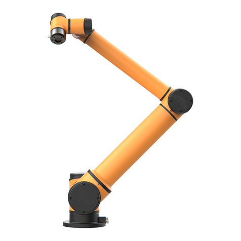
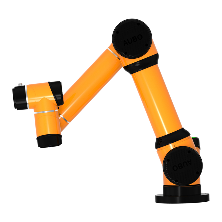
Product outline structure is shown in picture above.
More Information
If you need more information, please visit our official website at: www.aubo-robotics.com

V4.5
©2015-2019 AUBO.All rights reserved. 9
1. SAFETY
Introduction
This chapter introduces the principles and norms that should be followed when operating a robot or
robot systems. Integrators and users must read the relevant description in this manual carefully and
fully understand and strictly adhere to thewarning symbols in the contents. Because of the
complexity and highly risks of the robot system, operators need to be fully aware of the operation
risks and follow the requirements and specifications in this manual. Both the integrators and users
should have adequate safety awareness and follow the Industrial robots’ safety regulations, ISO
10218.
Warning Symbols in this Manual
The table below defines the captions specifying the danger levels used throughout this manual.
These warnings, which are relevant to safety, must be observed.
This indicates an imminently hazardous electrical situation which, if not
avoided, could result in death or serious injury.
This indicates a potentially hazardous hot surface which, if touched, could result
in injury.
This indicates an imminently hazardous situation which, if not avoided, could
result in injury or major damage to the equipment.

V4.5
©2015-2019 AUBO.All rights reserved. 10
This indicates a potentially hazardous electrical situation which, if not avoided,
could result in injury or major damage to the equipment.
This indicates a potentially situation which, if not avoided, could result in injury
or major damage to the equipment. Marked with this symbol, depending on the
circumstances, sometimes may have significant consequences.
This indicates a situation which, if not avoided, could result in injury or major
damage to the equipment. Marked with this symbol, depending on the
circumstances, sometimes may have significant consequences.
Safety Precautions
General
This manual includes safety precautions for protecting the user and preventing damage to the
machine. Users need to learn all the relevant descriptions and fully understand the safety precautions.
In this manual, we try to describe all the various situation as much as possible. However, we cannot
describe all the matters, which must not be done or which cannot be done, because there are so many
possibilities.
Terms and Conditions
The following basic information needs to be understood and followed when using the robot or robot
system for the first time. Also, other safety-related information will be introduced in other parts of
this manual. However, it may not cover everything. In practical applications, it is necessary to
analyze specific issues.

V4.5
©2015-2019 AUBO.All rights reserved. 11
1. Make sure to install the robot and all electrical equipment according to the
manual requirements and specifications.
2. Make sure to conduct a preliminary test and have inspection forrobots and
its protection systems before using the robot or putting it into productionfor
the first time.
3. Make sure to check the system and equipment for completion, operational
safety, and any damage that can be detected before starting the system and
equipment for the first time. The test needs to confirm whether it accords
with valid safety production rules and regulations in country or region. All
safety functions must be tested.
4. Make sure that all safety parameters and user programs are correct, and all
safety functions are working normally. A qualified robotics operator is
needed to check each safety function. Only pass the thorough, careful safety
test and reach the safe level, we can power on the robot.
1. Installation and commissioning needs to be performed by professionals in
accordance with the installation standards.
2. When the robot is installed, a comprehensive risk assessment is necessary,
and the test results need to be recorded in a report.
3. Set and modify the safety parameters by a qualified person. Use password or
isolation measures to prevent unauthorized people from setting and
modifying safety parameters. After a safety parameter is modified, the
related safety functions need to be analyzed.
4. When the robot is in an accident or abnormal operation, the emergency stop
switch needs to be pressed down to stop the movement.
5. AUBO-i3 joint module has brakes inside, it will remain manipulator’s pose
when power outage occurred. Don’t power on and power off frequently. It is
recommended that the time interval of each switch should be more than 10s.
6. AUBO-i3 has collision detecting function. When the external force of the
manipulator is beyond the users’ safety range, the manipulator will
automatically stop to prevent the robot or operator from damage or injury.
This function is a particularly for the safety of cooperative work, but robot
system must be in the normal operating range and use the AUBO series
control box. If the user develops the controller personally, the robot will not
have the functions above, and all the dangerous consequences are
undertaken by its owner.

V4.5
©2015-2019 AUBO.All rights reserved. 12
1. Make sure that the robot's joints and tools are installed properly and safely.
2. Make sure that there is enough space for the manipulator to move freely.
3. Don’t use robot if the robot is damaged.
4. Do not connect any safety equipment to normal I/O. Use safety-related
interfaces only.
5. Make sure to use the correct installation settings (e.g. the robot's mounting
angle, TCP weight, TCP offset, security configuration). Save and load the
installations file along with the program.
6. Tools and barriers should not have sharp edges or pinch points. Make sure
that all people keep their heads and faces outside the reach of the robot.
7. Be aware of robot’s movement when using the teach pendant.
8. Any strike would release a large amount of kinetic energy, which is much
higher than the case of high speed and high payload.
9. The different mechanical linking may increase the risk or lead to new
dangers. Make sure to perform a comprehensive risk assessment for entire
installation. Always choose the highest-level performance when different
safety and emergency shutdown performance level is needed. Make sure to
read and understand all the devices’ manual used for installation.
10. Do not modify the robot. Changes to the robot may cause unpredictable
danger to the integrator. The robots authorize restructuring need in
accordance with the latest version of all relevant service manuals. If the
robot is changed or altered in any way, AUBO (Beijing) Robotics
Technology Co., Ltd disclaims all liability.
11. User needs to check the insulation and protection measures before
transportation.
12. Transporting robots must follow the transport requirements. Handing
carefully and avoid t bumps.
1. The robot and control box generate heat during operation. Do not handle or
touch the robot while rthe robot is working or just stop working.
2. To cool the robot down, power off the robot and wait for one hour.
3. Never stick fingers behind the internal cover of the control box.

V4.5
©2015-2019 AUBO.All rights reserved. 13
1. When the robot is combined with or working with machines capable of
damaging the robot, then it is highly recommended to test all the functions
of the robot and the robot program separately. It is recommended to test the
robot program using temporary waypoints outside the workspace of other
machines.
2. AUBO (Beijing) Robotics Technology Co., Ltd cannot be held responsible
for any damages caused to the robot or to other equipment due to
programming errors or malfunctioning of the robot.
3. Don't expose the robot to a permanent magnetic field. Very strong magnetic
fields can damage the robot.

V4.5
©2015-2019 AUBO.All rights reserved. 14
Operator safety
In the operation of the robot system, we must ensure the safety of the operators first. The general
precautions are listed in the table below. Please take appropriate measures to ensure the safety of
operators.
1. Each operator who uses the robotic system should be trained through a
training course hosted by AUBO (Beijing) Robotics Technology Co., Ltd.
Users need to make sure to fully grasp the safe and standardized operating
procedures with the robot operating qualifications. Please inquire for
training details, mail service@aubo-robotics.com
2. Do not wear loose clothing or jewelry when working with the robot. Make
sure long hair is tied back when working with the robot.
3. When the device is running, even if the robot seems to stop, it is possible
that robot is waiting for the signal and in the upcoming action status. Even
in such state, it should be considered as the robot is in action.
4. A line should be drew to mark the range of motion of the robot to let the
operator knows the robot’s, including the holding tools, (like mechanical
hand or tools) operating range.
5. Make sure to set security-building measures (for example, rails, ropes, or
protective screen) near the robot operating area to protect the operator
and surrounding crowd. The lock should be set as needed so that those
who are not operators cannot access the robot power supply.
6. When using the operation panel or the teach pendant, make sure to take off
the gloves in case of operational errors.
7. Pushing or pulling the robot arm (at least 700N), force the joint to move in
the emergency or abnormal condition (like a person is caught in or
surrounded by a robot). Manually move the robot arm without electric
drive only for emergency, and it may damage the joints.

V4.5
©2015-2019 AUBO.All rights reserved. 15
Responsibility and standard
AUBO-i3 can be combined with other equipments to form a complete machine, and itself is not
complete. The information in this manual does not cover how to design, install and operate a
complete robot, nor does it cover all peripheral equipments that can influence the safety of the
complete system. The safety of installing a complete robot is determined by how it integrated.
Integrators must follow the standards and regulations and laws of the country where the robot is
installed to perform a risk assessment for its system design and installation. Risk assessment is one
of the most important things that integrators must done. Guidance on the risk assessment process
may be found in the following standards.
•ISO 12100:2010 Safety of machinery - General principles for design - Risk assessment and
risk reduction.
•ISO 10218-2:2011 Robots and robotic devices - Safety requirements - Part 2: Industrial robot
systems and integration.
•RIA TR R15.306-2014 Technical Report for Industrial Robots and Robot Systems - Safety
Requirements, Task-based Risk Assessment Methodology.
•ANSI B11.0-2010 Safety of Machinery; General Requirements & Risk Assessment.
AUBO robot integrators need to fulfill but not limited to the following responsibilities:
•Comprehensive risk assessment of complete robot system;
•Make sure the whole system design and installation is correct;
•Provide training to users and personnel;
•Create operational specifications for a complete system, specify instructions for process;
•Establish appropriate safety measures;
•Use appropriate methods to eliminate or minimize all hazards to acceptable level in the final
installation;
•Convey the residual risk to the users;
•Mark the logo and contact information of the integrators on the robot;
•Archive technical file
Guidance on how to find and read applicable standards and laws is provided on: www.aubo-
robotics.com
All safety information contained in this manual are not considered as a guarantee for AUBO (Beijing)
Robotics Technology Co., Ltd. Even if all the safety instructions are observed, the personnel injury
or equipment damage caused by the operator is still likely to occur.
AUBO (Beijing) Robotics Technology Co., Ltd is committed to continuously improve the reliability
and performance of the product. Therefore, we reserve the right to upgrade products without notice.

V4.5
©2015-2019 AUBO.All rights reserved. 16
AUBO (Beijing) Robotics Technology Co., Ltd seeks to ensure the accuracy and reliability of the
contents in this manual but is not responsible for any errors or omissions.
This manual suits for next models
2
Table of contents
Other AUBO Robotics manuals
