ABB IRT 710 User manual

ROBOTICS
Product manual
IRT 710

Trace back information:
Workspace Systems version a40
Checked in 2023-10-18
Skribenta version 5.5.019

Product manual
IRT 710
IRC5
Document ID: 3HKA00000186299-001
Revision: B
© Copyright 2023 ABB. All rights reserved.
Specifications subject to change without notice.

The information in this manual is subject to change without notice and should not
be construed as a commitment by ABB. ABB assumes no responsibility for any errors
that may appear in this manual.
Except as may be expressly stated anywhere in this manual, nothing herein shall be
construed as any kind of guarantee or warranty by ABB for losses, damage to persons
or property, fitness for a specific purpose or the like.
In no event shall ABB be liable for incidental or consequential damages arising from
use of this manual and products described herein.
This manual and parts thereof must not be reproduced or copied without ABB's
written permission.
Keep for future reference.
Additional copies of this manual may be obtained from ABB.
Original instructions.
© Copyright 2023 ABB. All rights reserved.
Specifications subject to change without notice.

Table of contents
9Overview of this manual ...................................................................................................................
11Product documentation ....................................................................................................................
13How to read the product manual ......................................................................................................
151 Safety
151.1 Safety information ............................................................................................. 151.1.1 Limitation of liability ................................................................................. 171.1.2 Requirements on personnel ...................................................................... 181.1.3 Safeguarded space .................................................................................. 221.2 Safety actions ................................................................................................... 221.2.1 Personal protective equipment .................................................................. 231.2.2 Fire extinguishing .................................................................................... 241.2.3 Emergency release .................................................................................. 251.2.4 Make sure that the main power has been switched off .................................... 261.3 Safety risks ...................................................................................................... 261.3.1 Safety risks during installation and service work ........................................... 281.3.2 Moving equipment is potentially lethal ......................................................... 291.3.3 First test run may cause injury or damage .................................................... 301.3.4 Work inside the working range of the Product ............................................... 311.3.5 Enabling device and hold-to-run functionality ............................................... 321.3.6 Risks associated with live electric parts ....................................................... 341.3.7 Hot parts may cause burns ....................................................................... 351.3.8 Brake testing .......................................................................................... 361.3.9 Safety risks during handling of batteries ...................................................... 371.3.10 Safety risks during work with gearbox lubricants (oil or grease) ....................... 391.4 Safety signals and symbols ................................................................................. 391.4.1 Safety signals in the manual ...................................................................... 401.4.2 Safety symbols on product labels ............................................................... 461.5 Product stopping functions ................................................................................. 481.6 Safety during installation and commissioning ......................................................... 501.7 Safety during operation ...................................................................................... 521.8 Safety during maintenance and repair ................................................................... 521.8.1 Safety during maintenance and repair ......................................................... 551.8.2 Emergency release of the Product axes ....................................................... 561.9 Safety during troubleshooting .............................................................................. 571.10 Safety during decommissioning ...........................................................................
592 Technical data
592.1 Technical data .................................................................................................. 662.2 Working range ................................................................................................. 822.3 Information labels .............................................................................................. 832.4 IRT 710 terms ...................................................................................................
853 Installation and commissioning
853.1 Introduction to installation and commissioning ....................................................... 863.2 Overview of installation and commissioning procedure ............................................ 873.3 Unpacking ....................................................................................................... 873.3.1 Pre-installation procedure ......................................................................... 893.3.2 Acceptance inspection ............................................................................. 903.3.3 Storage ................................................................................................. 903.3.3.1 Storing the cable chain ................................................................. 923.4 On-site installation ............................................................................................ 923.4.1 Track motion IRT 710 overview .................................................................. 973.4.2 Track motion IRT 710 layout ...................................................................... 993.4.3 Lifting with lifting accessories .................................................................... 993.4.3.1 Lifting and moving track motion IRT 710 ..........................................
Product manual - IRT 710 5
3HKA00000186299-001 Revision: B
© Copyright 2023 ABB. All rights reserved.
Table of contents

1103.4.4 Foundation ............................................................................................ 1163.4.5 Screw joints ........................................................................................... 1173.4.6 Moving the carriage manually .................................................................... 1203.4.7 Assembling the track motion IRT 710 .......................................................... 1203.4.7.1 Assembling the sections ............................................................... 1283.4.7.2 Recommendations for floor mounting .............................................. 1333.4.7.3 Geometric alignment of track motion IRT 710 .................................... 1393.4.8 Assembling the pedestal (option) ............................................................... 1413.4.9 Assembly of the manipulator ..................................................................... 1433.5 Electrical installation .......................................................................................... 1433.5.1 Cabling of the IRT 710 .............................................................................. 1453.5.2 Specifications of the movement cables ........................................................ 1463.5.3 Installation of the cable chain .................................................................... 1503.5.4 SMB box ................................................................................................ 1543.5.5 Connectors on IRC5 controller ................................................................... 1563.5.6 Connectors on Drive Module ..................................................................... 1573.5.7 Assembly the cable of the additional axes SMB ............................................ 1583.5.8 Grounding point ...................................................................................... 1603.5.9 Cables connections ................................................................................. 1643.5.10 Harness outlet ........................................................................................ 1713.5.11 Inspection points of cable chain prior to start-up ........................................... 1723.6 Software installation .......................................................................................... 1723.6.1 Creating and downloading a system ........................................................... 1743.6.2 Updating the revolution counter on the track motion ...................................... 1753.7 Lubrication ....................................................................................................... 1753.7.1 Activating the automatic lubrication system .................................................. 1773.7.2 Lubrication feedback (optional) .................................................................. 1783.8 Zone division ....................................................................................................
1794 Maintenance
1794.1 Introduction ...................................................................................................... 1804.2 Maintenance schedule and expected component life ............................................... 1804.2.1 Specification of maintenance intervals ........................................................ 1814.2.2 Maintenance schedule ............................................................................. 1834.2.3 Expected component life ......................................................................... 1844.3 Inspection activities ........................................................................................... 1844.3.1 Inspecting the information labels ............................................................... 1864.3.2 Inspecting the lubrication system ............................................................... 1884.3.3 Inspecting the cable chain ........................................................................ 1904.3.4 Inspecting the levelling screw .................................................................... 1924.3.5 Inspecting the rectangular rails .................................................................. 1944.3.6 Inspecting the cam roller units ................................................................... 1964.3.7 Inspecting the felt wiper ........................................................................... 1984.3.8 Inspecting the cables and connectors ......................................................... 1994.3.9 Inspecting the mechanical stops ................................................................ 2004.3.10 Inspecting the gearbox, back lash .............................................................. 2024.4 Cleaning activities ............................................................................................. 2024.4.1 Cleaning the IRT 710 ............................................................................... 2044.4.2 Cleaning and lubricating the gear racks ....................................................... 2054.4.3 Cleaning and lubricating the rectangular rails ............................................... 2074.5 Lubrication activities .......................................................................................... 2074.5.1 Adjusting the leveling ............................................................................... 2084.5.2 Automatic lubrication system ..................................................................... 2144.6 Replacement/changing activities .......................................................................... 2144.6.1 Replacing the SMB battery pack ................................................................ 2164.6.2 Replacing the grease package and battery ................................................... 2174.6.3 Replenishing oil, cam roller unit .................................................................
6 Product manual - IRT 710
3HKA00000186299-001 Revision: B
© Copyright 2023 ABB. All rights reserved.
Table of contents

2195 Repair
2195.1 Introduction ...................................................................................................... 2205.2 Replacing the carriage parts ................................................................................ 2205.2.1 Replacing the motor and gearbox ............................................................... 2345.2.2 Replacing the cam roller units ................................................................... 2445.2.3 Replacing the scraper parts ...................................................................... 2495.2.4 Replacing the lubrication parts ................................................................... 2585.3 Replacing the track parts .................................................................................... 2595.3.1 Replacing the covers ............................................................................... 2615.3.1.1 Replacing the track covers ............................................................ 2635.3.1.2 Replacing the terminal covers ........................................................ 2655.3.1.3 Replacing the rack covers ............................................................. 2675.3.2 Replacing the rectangular rails ................................................................... 2715.3.3 Replacing the racks ................................................................................. 2755.3.4 Replacing the mechanical stops ................................................................. 2795.4 Replacing the cable chain parts ........................................................................... 2795.4.1 Replacing the cable chain covers ............................................................... 2815.4.1.1 Replacing the external cable chain covers ........................................ 2835.4.1.2 Replacing the cable chain terminal covers ........................................ 2855.4.2 Replacing the cable chain parts ................................................................. 2885.4.2.1 Replacing the outer cable chain link ................................................ 2955.4.2.2 Replacing the inner cable chain link ................................................ 3025.4.2.3 Replacing the vertical separators .................................................... 3075.4.2.4 Replacing the movable chain end ................................................... 3145.4.2.5 Replacing the fixed chain end ........................................................ 3185.4.2.6 Replacing the cables in cable chain ................................................
3356 Calibration
3356.1 Introduction to calibration ................................................................................... 3356.1.1 Introduction and calibration terminology ...................................................... 3366.1.2 Calibration methods ................................................................................. 3376.1.3 When to calibrate .................................................................................... 3386.2 Synchronization marks and track motion movement directions .................................. 3386.2.1 Synchronization marks and synchronization position for track motions ............. 3426.3 Updating revolution counters ............................................................................... 3426.3.1 Updating revolution counters for axis calibration ........................................... 3446.3.2 Updating revolution counters for pin calibration ............................................ 3456.4 Calibrating with Axis Calibration method ............................................................... 3466.4.1 Description of Axis Calibration .................................................................. 3486.4.2 Calibration tools for Axis Calibration ........................................................... 3506.4.3 Installation locations for the calibration tools ............................................... 3516.4.4 Axis Calibration - Running the calibration procedure ...................................... 3556.4.5 Reference calibration ............................................................................... 3576.5 Pin calibration .................................................................................................. 3596.6 Checking the synchronization position ..................................................................
3617 Decommissioning
3617.1 Environmental information .................................................................................. 3637.2 Scrapping of robot .............................................................................................
3658 Reference information
3658.1 Introduction ...................................................................................................... 3668.2 Applicable standards ......................................................................................... 3678.3 Unit conversion ................................................................................................. 3688.4 Screw joints .................................................................................................... 3718.5 Weight specifications ......................................................................................... 3728.6 Standard toolkit ................................................................................................ 3738.7 Special tools ....................................................................................................
Product manual - IRT 710 7
3HKA00000186299-001 Revision: B
© Copyright 2023 ABB. All rights reserved.
Table of contents

3768.8 Lifting accessories and lifting instructions ..............................................................
3779 Spare parts
3779.1 Spare part lists and illustrations ...........................................................................
37910 Circuit diagrams
381Index
8 Product manual - IRT 710
3HKA00000186299-001 Revision: B
© Copyright 2023 ABB. All rights reserved.
Table of contents

Overview of this manual
About this manual
This manual contains instructions for:
• mechanical and electrical installation of the IRT 710
• maintenance of the IRT 710
• mechanical and electrical repair of the IRT 710
The robot described in this manual has the following protection types:
•Standard
Product manual scope
The manual covers all variants and designs of the IRT 710. Some variants and
designs may have been removed from the business offer and are no longer available
for purchase.
Usage
This manual should be used during:
• installation and commissioning, from lifting the product to its work site and
securing it to the foundation, to making it ready for operation
• maintenance work
• repair work
• decommissioning work
Note
It is the responsibility of the integrator to conduct a risk assessment of the final
application.
It is the responsibility of the integrator to provide safety and user guides for the
robot system.
Who should read this manual?
This manual is intended for:
• installation personnel
• maintenance personnel
• repair personnel.
Prerequisites
A maintenance/repair/installation craftsman working with an ABB robot must:
• be trained by ABB and have the required knowledge of mechanical and
electrical installation/repair/maintenance work.
• be trained to respond to emergencies or abnormal situations.
Continues on next page
Product manual - IRT 710 9
3HKA00000186299-001 Revision: B
© Copyright 2023 ABB. All rights reserved.
Overview of this manual

References
Documentation referred to in the manual, is listed in the table below.
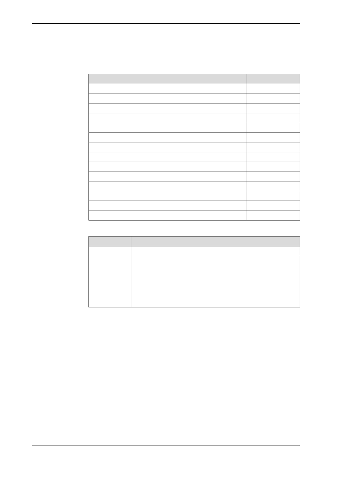
Document IDDocument name
3HKA00000191844Product specification - IRT 710
3HAC021313-001Product manual - IRC5
3HAC16590-1Operating manual - IRC5 with FlexPendant
3HAC025709-001Service Information System - IRC5
3HAC021395-001Application manual - Additional axes and stand alone controller
3HAC050948-001Technical reference manual - System parameters
3HAC056372-001IRB 7600 product manual
3HAC055424-001IRB 6650 product manual
3HAC044270-001IRB 6700 product manual
3HAC039838-001IRB 760 product manual
3HAC025755-001IRB 660 product manual
3HAC033453-001IRB 4600 product manual
3HAC022032-001IRB 4400 product manual
3HAC039842-001IRB 460 product manual
Revisions
DescriptionRevision
First edition.A
The following updates are done in this revision:
• Minor corrections.
• Updated content with new drive unit bracket and backlash tool.
• Updated creating and downloading a system procedures.
• Added harness outlet chapter.
• Updated IRB 6660 with 500 mm riser.
• Updated illustrations throughout the manual accordingly.
B
10 Product manual - IRT 710
3HKA00000186299-001 Revision: B
© Copyright 2023 ABB. All rights reserved.
Overview of this manual
Continued

Product documentation
Categories for user documentation from ABB Robotics
The user documentation from ABB Robotics is divided into a number of categories.
This listing is based on the type of information in the documents, regardless of
whether the products are standard or optional.
Tip
All documents can be found via myABB Business Portal, www.abb.com/myABB.
Product manuals
Manipulators, controllers, DressPack/SpotPack, and most other hardware is
delivered with a Product manual that generally contains:
• Safety information.
• Installation and commissioning (descriptions of mechanical installation or
electrical connections).
•Maintenance (descriptions of all required preventive maintenance procedures
including intervals and expected life time of parts).
• Repair (descriptions of all recommended repair procedures including spare
parts).
• Calibration.
• Troubleshooting.
• Decommissioning.
•Reference information (safety standards, unit conversions, screw joints, lists
of tools).
• Spare parts list with corresponding figures (or references to separate spare
parts lists).
• References to circuit diagrams.
Technical reference manuals
The technical reference manuals describe reference information for robotics
products, for example lubrication, the RAPID language, and system parameters.
Application manuals
Specific applications (for example software or hardware options) are described in
Application manuals. An application manual can describe one or several
applications.
An application manual generally contains information about:
• The purpose of the application (what it does and when it is useful).
•What is included (for example cables, I/O boards, RAPID instructions, system
parameters, software).
• How to install included or required hardware.
• How to use the application.
Continues on next page
Product manual - IRT 710 11
3HKA00000186299-001 Revision: B
© Copyright 2023 ABB. All rights reserved.
Product documentation

• Examples of how to use the application.
Operating manuals
The operating manuals describe hands-on handling of the products. The manuals
are aimed at those having first-hand operational contact with the product, that is
production cell operators, programmers, and troubleshooters.
12 Product manual - IRT 710
3HKA00000186299-001 Revision: B
© Copyright 2023 ABB. All rights reserved.
Product documentation
Continued

How to read the product manual
Reading the procedures
The procedures contain all information required for the installation or service activity
and can be printed out separately when needed for a certain service procedure.
Safety information
The manual includes a separate safety chapter that must be read through before
proceeding with any service or installation procedures. All procedures also include
specific safety information when dangerous steps are to be performed.
Read more in the chapter Safety on page 15.
Illustrations
The product is illustrated with general figures that does not take painting or
protection type in consideration.
Likewise, certain work methods or general information that is valid for several
product models, can be illustrated with illustrations that show a different product
model than the one that is described in the current manual.
Product manual - IRT 710 13
3HKA00000186299-001 Revision: B
© Copyright 2023 ABB. All rights reserved.
How to read the product manual

This page is intentionally left blank

1 Safety
1.1 Safety information
1.1.1 Limitation of liability
Limitation of liability
Any information given in this manual regarding safety must not be construed as a
warranty by ABB that the IRT 710 (hereinafter, the Product) will not cause injury
or damage even if all safety instructions are complied with.
The information does not cover how to design, install and operate a complete
system, nor does it cover all peripheral equipment that can influence the safety of
the entire system.
In particular, liability cannot be accepted if injury/damage has been caused for any
of the following reasons:
• Use of the Product in other ways than intended.
• Incorrect operation or maintenance.
• Operation of the Product when the safety devices are defective, not in their
intended location or in any other way not working.
• When instructions for operation and maintenance are not followed.
• Non-authorized design modifications made in or around the Product.
• Repairs carried out by in-experienced or non-qualified personnel.
• Foreign objects.
• Force majeure.
Nation/region specific regulations
To protect personnel, the complete system must be designed and installed in
accordance with the safety requirements set forth in the standards and regulations
of the country where the Product is installed.
To be observed by the supplier of the complete system
The integrator is responsible that the safety devices necessary to protect people
working with the Product are designed and installed correctly.
When integrating the Product with external devices and machines:
• The supplier of the complete system must ensure that all circuits used in the
safety function are interlocked in accordance with the applicable standards
for that function.
• The supplier of the complete system must ensure that all circuits used in the
emergency stop function are interlocked in a safe manner, in accordance
with the applicable standards for the emergency stop function.
Continues on next page
Product manual - IRT 710 15
3HKA00000186299-001 Revision: B
© Copyright 2023 ABB. All rights reserved.
1 Safety
1.1.1 Limitation of liability

The integrator of the final application is required to perform an assessment of the
hazards and risks (HRA).
Note
The integrator is responsible for the safety of the final application.
Safe access
The Product shall be designed to allow safe access to all areas where intervention
is necessary during operation, adjustment, and maintenance.
Where it is necessary to perform tasks within the safeguarded space there shall
be safe and adequate access to the task locations.
Safety zones, which must be crossed before admittance, must be set up in front
of the Product's working space. Light beams or sensitive mats are suitable devices.
Turntables or the like should be used to keep the operator out of the Product's
working space.
A safety fence is recommended to ensure safeguarded space. Sufficient space
must be provided around the Product to protect those working with or on it from
hazards such as crushing.
The fence or enclosure must be dimensioned to withstand the force created if the
load being handled by the Product is dropped or released at maximum speed.
Also consider the maximum possible impact caused by a breaking or malfunctioning
rotating tool or other device fitted to the Product.
Safe handling
Users shall not be exposed to hazards, including slipping, tripping, and falling
hazards.
It must be possible to safely turn off tools, such as milling cutters, etc. Make sure
that guards remain closed until the cutters stop rotating.
It should be possible to release parts by manual operation (valves).
Safe design
Emergency stop buttons must be positioned in easily accessible places so that
the Product can be stopped quickly. If any of the buttons do not stop all the product
workcell motion, each emergency stop button must be marked, if more than one
is provided, to indicate its designated safety function.
Grippers/end effectors must be designed so that they retain work pieces in the
event of a power failure or a disturbance to the controller.
Unauthorized modifications of the originally delivered product/system are prohibited.
Without the consent of ABB it is forbidden to attach additional parts through welding,
riveting, or drilling of new holes into the castings. The strength could be affected.
CAUTION
Ensure that a gripper is prevented from dropping a work piece, if such is used.
16 Product manual - IRT 710
3HKA00000186299-001 Revision: B
© Copyright 2023 ABB. All rights reserved.
1 Safety
1.1.1 Limitation of liability
Continued

1.1.2 Requirements on personnel
General
Only personnel with appropriate training are allowed to install, maintain, service,
repair, and use the robot. This includes electrical, mechanical, hydraulics,
pneumatics, and other hazards identified in the risk assessment.
Persons who are under the influence of alcohol, drugs or any other intoxicating
substances are not allowed to install, maintain, service, repair, or use the robot.
The plant liable must make sure that the personnel is trained on the robot, and on
responding to emergency or abnormal situations.
Personal protective equipment
Use personal protective equipment, as stated in the instructions.
Product manual - IRT 710 17
3HKA00000186299-001 Revision: B
© Copyright 2023 ABB. All rights reserved.
1 Safety
1.1.2 Requirements on personnel

1.1.3 Safeguarded space
Light curtain to protect hands from entering hazardous areas
d<40 mm
When the detection diameter of the light curtain sensor d<40 mm, this type of light
curtain can be used to protect the hands and fingers from entering the dangerous
area.
The calculation formula corresponding to the minimum safety distance is:
S = K*T+C
K = 2000 mm/s (Approaching speed of the hands)
T = The maximum time for the machine to stop + Light curtain response time
C = 8(d-14) (Traverse distance)
d = Light curtain detection capability
d>40 mm
When the detection diameter of the sensor d>40 mm, it cannot detect the intrusion
of the hand, but can only detect the body.
The calculation formula corresponding to the minimum safety distance is:
S = K*T+C
K = 2000 mm/s (Approaching speed of the walking human)
T = The maximum time for the machine to stop + Light curtain response time
C = 850 mm (Traverse distance)
d = Light curtain detection capability
Note
If the recalculated value ≤ 500mm, then S should be set as 500 mm.
Note
The used light curtain should follow type 4 from IEC61496 standards.
Continues on next page
18 Product manual - IRT 710
3HKA00000186299-001 Revision: B
© Copyright 2023 ABB. All rights reserved.
1 Safety
1.1.3 Safeguarded space

xx2200000842
Safety door with interlock device for mechanical safety fence
The calculation formula corresponding to the minimum safety distance is:
S = K*T+C
K = 2000 mm/s (Approaching speed of the walking human)
T = The maximum time for the machine to stop + Interlock response time
C = 850 mm (Traverse distance)
Note
If the recalculated value ≤ 500mm, then S should be set as 500 mm.
Note
The interlock device should follow the dual channel requirements.
Continues on next page
Product manual - IRT 710 19
3HKA00000186299-001 Revision: B
© Copyright 2023 ABB. All rights reserved.
1 Safety
1.1.3 Safeguarded space
Continued

Safety fence to protect body from entering hazardous areas
Regular openings for persons of 14 years of age and above
The following table gives srfor regular openings for persons of 14 years of age
and above.
The dimensions of openings, e, correspond to the side of a square opening, the
diameter of a round opening and the narrowest dimension of a slot opening.
For openings > 120 mm, safety distances in accordance with 4.2.2 shall be used.
Note
Measures for children's protection against strangulation are not covered by this
International Standard.
Reaching through regular openings — Persons of 14 years of age and above
Safety distance, sr
OpeningIllustrationPart of body
RoundSquareSlot
≥2≥2≥2e≤4
xx2200000857
Fingertip
≥5≥5≥104<e≤6
≥5≥15≥206<e≤8
xx2200000858
Finger up to
knuckle joint ≥20≥25≥808<e≤10
≥80≥80≥10010<e≤12
xx2200000859
Hand
≥120≥120≥12012<e≤20
≥120≥120≥850i
20<e≤30
≥120≥200≥85030<e≤40
xx2200000860
Arm up to
junction with
shoulder ≥850≥850≥85040<e≤100
iIf the length of the slot opening is ≤ 65 mm, the thumb will act as a stop and the safety distance
can be reduced to 200 mm.
Note
The height of the fence should be at least or higher than 2200 mm.
Continues on next page
20 Product manual - IRT 710
3HKA00000186299-001 Revision: B
© Copyright 2023 ABB. All rights reserved.
1 Safety
1.1.3 Safeguarded space
Continued
Table of contents
Other ABB Robotics manuals

ABB
ABB OmniCore C90XT User manual

ABB
ABB IRB1410 User manual

ABB
ABB IRB 6650S User manual

ABB
ABB IRB6400 Instruction Manual

ABB
ABB IRB 1200 User manual

ABB
ABB IRB 4600 - 40/2.55 User manual

ABB
ABB IRB 14000 User manual

ABB
ABB DressPack IRB 6700 User manual

ABB
ABB 180 Comfort User manual

ABB
ABB IRB 760 Series User manual

ABB
ABB Feather Duster User manual

ABB
ABB OmniCore V250XT Type B User manual

ABB
ABB IRB 6600 - 225/2.55 type B User manual

ABB
ABB CRB 1300 User manual

ABB
ABB IRB 140 User manual

ABB
ABB IRB 8700 Series User manual

ABB
ABB IRB 6640 Foundry Prime User manual

ABB
ABB IRB 6640 - 180/2.55 User manual

ABB
ABB MultiMove Instructions for use

ABB
ABB IRB-M100 Owner's manual